EP0894900B1 - Pfahlgründungsstruktur - Google Patents
Pfahlgründungsstruktur Download PDFInfo
- Publication number
- EP0894900B1 EP0894900B1 EP98901533A EP98901533A EP0894900B1 EP 0894900 B1 EP0894900 B1 EP 0894900B1 EP 98901533 A EP98901533 A EP 98901533A EP 98901533 A EP98901533 A EP 98901533A EP 0894900 B1 EP0894900 B1 EP 0894900B1
- Authority
- EP
- European Patent Office
- Prior art keywords
- pile
- footing
- head
- supporting
- spherical
- Prior art date
- Legal status (The legal status is an assumption and is not a legal conclusion. Google has not performed a legal analysis and makes no representation as to the accuracy of the status listed.)
- Expired - Lifetime
Links
Images


Classifications
-
- E—FIXED CONSTRUCTIONS
- E02—HYDRAULIC ENGINEERING; FOUNDATIONS; SOIL SHIFTING
- E02D—FOUNDATIONS; EXCAVATIONS; EMBANKMENTS; UNDERGROUND OR UNDERWATER STRUCTURES
- E02D27/00—Foundations as substructures
- E02D27/32—Foundations for special purposes
- E02D27/34—Foundations for sinking or earthquake territories
-
- E—FIXED CONSTRUCTIONS
- E02—HYDRAULIC ENGINEERING; FOUNDATIONS; SOIL SHIFTING
- E02D—FOUNDATIONS; EXCAVATIONS; EMBANKMENTS; UNDERGROUND OR UNDERWATER STRUCTURES
- E02D29/00—Independent underground or underwater structures; Retaining walls
- E02D29/12—Manhole shafts; Other inspection or access chambers; Accessories therefor
-
- E—FIXED CONSTRUCTIONS
- E02—HYDRAULIC ENGINEERING; FOUNDATIONS; SOIL SHIFTING
- E02D—FOUNDATIONS; EXCAVATIONS; EMBANKMENTS; UNDERGROUND OR UNDERWATER STRUCTURES
- E02D2300/00—Materials
- E02D2300/0001—Rubbers
Definitions
- the present invention relates to a pile foundation structure for supporting a footing serving as a foundation of an upper structure and propagating a load of the upper structure to the underground depths by means of a point bearing pile or a friction pile for being driven into the underground such as a solid rock.
- Such a kind of a pile foundation structure conventionally known is a structure illustrated in Fig. 4.
- a point pile or a friction pile 82 as a structural element, is driven into the underground 81 such as a solid rock, a bottom of a footing 83 is mounted on the head of the pile 82, and the pile 82 and the footing 83 are rigidly bound by a reinforcing steel member 84 including a pile reinforcement and a concrete-reinforcing bar and a concrete.
- the pile foundation structure shown in Fig. 5 is structurally described below.
- a number of steel reinforcement members 92 annularly disposed on an upper end of a concrete pile 91, and steel pipes 93 for surrounding the steel reinforcement members 92 in a state of allowing lateral movement of the steel reinforcement members 92 are upwardly extended.
- annular engagement projections 94 are arranged so as to be connected to an upper end portion of the concrete pile 91 in a buried state.
- a top board 95 is welded to the upper end portion of the steel pipes 93, the top board 95 is provided with flexible holes 96 for making the steel reinforcement members 92 pierce the top board 95 so as to respectively allow lateral shaking of the steel reinforcement members 92.
- the steel reinforcement members 92 protruding above the top board 95 through the flexible holes 96, are connected to the concrete structure body (or the footing) 97 of the upper portion thereof. Furthermore, there is interposingly a sliding member 99 between the top board 95 and a footing metal member 98, through which the concrete structure body 97 is slidably mounted on the top board 95.
- JP-A-59134230 describes an earthquake resistant structure and the protection of a pile by interposing buffer material. This buffer material is interposed between the pile and in a recession in the bottom of the structure.
- US-A-5081806 describes a foundation system for buildings and other structures.
- the system comprises a fixed support base with a hardened three dimensional curved member located between a hardened dished top surface of the base and a hardened dished cup on the underside of a concrete beam.
- the three dimensional curved member is of elliptical or similar shape and permits a horizontal movement of the dished top surface relative to the dished cup when a seismic wave or shock wave occurs.
- WO 91/12398 describes an anti-seismic building comprised of a double clothing structure having two superimposed floating floors of reinforced concrete. The lower floor rests on a hedgehog of keels anchored in the ground whereas the upper floor rests with two crossed layers of alternate rollers made of concrete or of elastomer.
- JP-A-63289124 describes a structure resting on pillars.
- the head of the pillar is convex or concave shaped and rests on a correspondingly concave or convex shapes bottom surface of the overlaying structure.
- the convex and concave shaped surfaces are covered by metal parts.
- UK-A-2291076 describes a building foundation which absorbs earth tremors. For that purpose blocks of finely divided rubber tires bounded in a matrix of rubber are laid into the foundation of the building under the wall. Further a back-fill of divided tires is laid inside the blocks to be a rest for a concrete baseplate of the building.
- Objects of the present invention is to provide a pile foundation structure which can prevent a damage or a destroy of the pile head and a footing by releasing a stress applied to a binding portion of a pile head, even in applying a great external force such as the earthquake, and enhance an execution and achieve a low-cost by means of decreasing an amount of arrangement of reinforcing steel employed for the pile and the footing.
- a pile foundation structure having a footing arranged on a side of a head of a pile in the underground comprises:
- a sliding member is interposed between the flat top surfaces of the protrusive supporting-portion disposed on the pile head portion and the recessed binding-portion disposed on the bottom of the footing, the top surfaces are opposed to each other, thereby building a roller bearing structure for making it possible to relatively slidingly move the binding portion of the head of the pile in a horizontal direction. Whereby it is possible to prevent a load of a shearing force, a bending moment or the like from being concentrated on the binding portion of the pile head in applying the external force.
- the roller bearing structure can prevent the pile head and the footing from being damaged or destroyed, thereby making it possible to decrease an amount of an arrangement of reinforcement used for the pile and footing, thereby enhancing an execution and achieving low-cost as effects.
- a pile foundation structure having a footing arranged on a side of a head of a pile in the underground comprises:
- the sliding member is interposed therebetween, thereby building the pin bearing structure for making it possible to relatively slidingly rotate the binding portion of the pile head.
- the binding portion of the pile head is isolated from the ground, the earthquake motion of the ground is decreased, thereby showing an earthquake avoidable effect for preventing the shaking from being propagated to the footing and the upper structure.
- the seismic force and a lateral shake of the upper structure are extremely decreased, thus obtaining improvement of the livability and enhancing further a damage-preventive effect of the upper structure.
- the pile foundation structure according to the first and second inventions has an arrangement wherein a calking compound is enclosed with the sliding surface between the supporting portion of the head of the pile and the binding portion of the bottom portion of the footing.
- the calking compound is enclosed with the sliding surface between the supporting portion of the head of the pile and the binding portion of the bottom portion of the footing, thereby enhancing the vibration absorption property, and making it possible to prevent water from intruding from an outside to the sliding surface. Accordingly, corrosion of a steel material as a structural element is decreased and deterioration of the sliding member is decreased, thereby keeping sliding movement and sliding rotation properties caused by the sliding member smooth and stable for a long period as effects.
- the pile foundation structure according to the first and second inventions has an arrangement wherein metal parts made of a metal are respectively fitted in an outer surface of the supporting portion of the head of the pile and an inner surface of the binding portion of the bottom portion of the footing in a closing state, and the metal parts are integrally connected to the head of the pile and the bottom of the footing via anchor members. Then, the arrangement can surely prevent the pile head and footing from being destroyed or damaged and keep predetermined sliding movement and sliding rotation properties smooth and stable.
- a material having a self-lubricative property is employed as the sliding material. Therefore, even in case that this is the first time that the structure wherein a long time passed since the execution of the structure has undergone the external force such as the earthquake, the predetermined sliding movement and sliding rotation properties are ensured.
- a pile foundation structure shown in Fig. 1 has an arrangement wherein a long pile 12 made of reinforced concrete is driven into the underground 11 such as a solid rock, a head of the pile 12 (or a pile head) is provided with a columnar protrusive supporting-portion 13 having a flat top surface so as to protrude above an upper surface of the underground 11.
- a pile metal part 14 made of a protrusive-seat-shaped metal (mainly steel) corresponding thereto is closely fitted in an outer surface of the protrusive supporting-portion 13 of the pile head. Additionally, an inner surface of the pile metal part 14 is integrally fixed and connected to the head of the pile 12 via a number of anchor members 15 made of steel, for fixation.
- the footing 18 is not linked to the pile 12 by reinforcement.
- the footing 18 is structurally separated from the pile 12.
- a footing metal part 20 made of a recessed seat-shaped metal (mainly steel) corresponding thereto is closely fitted in an inner surface of the recessed-binding-portion 19 on the bottom of the footing 18, and the outer surface of the footing metal part 20 is integrally fixed and connected to the bottom of the footing 18 via a number of anchor members 21 made of steel, for fixation.
- a sliding member 22 is disposed between the flat top surfaces of the pile metal part 14 fitted and fixed in the protrusive supporting-portion 13 on a side of the pile 12 and the footing metal 20 fitted and fixed in an inside of the recessed-binding-portion 19 on a side of the footing 18, thereby building a roller bearing structure for making it possible to relatively slidingly move the binding portion of the pile head in a horizontal direction, and an enclosing structure wherein a calking compound 23 is enclosed with a sliding surface (i.e., a clearance portion except a portion for disposing the sliding member 22) between the protrusive supporting-portion 13 on a side of the pile 12 and the recessed-binding-portion 19 on a side of the footing 18.
- a sliding surface i.e., a clearance portion except a portion for disposing the sliding member 22
- the sliding member 22 is adhesively bonded to a resin sheet made of a fluororesin or a polyethylene resin or the like, or it is coated with the fluororesin or the polyethylene resin.
- a solid lubricating material including a carbon material and a molybdenum material may be applied to the sliding surface of the resin sheet.
- a material employed as the calking compound 23 is a sealant material, a rubber packing or the like, having superiority in a cut-off of water property and a vibration absorbing property.
- a roller bearing structure is adopted wherein the pile metal part 14 is fitted and fixed in the protrusive supporting-portion 13 on a side of the head of the pile 12 and the footing metal part 20 is fitted and fixed in the recessed-binding-portion 19 on a side of the bottom of the footing 18, the flat top surfaces of the pile metal mart 14 and the footing metal part 20 are opposite to each other, and the sliding member 22 having the self-lubricating property is intervened between the flat top surfaces. Therefore, the bottom of the footing 18 and the head of the pile 12 are relatively slidingly movable in laterally and longitudinally horizontal directions (i.e., a direction of an arrow "a" in Fig. 1, and a cross dot direction).
- the present invention can prevent the head of the pile 12 and the footing 18 from being damaged and destroyed, thereby ensuring an earthquake proofing property, and an earthquake avoidable property, whereby an amount of arrangement of reinforcement, employed as the pile 12 and the footing 18, can be decreased and execution can be enhanced and costs thereof can be decreased.
- the crushed-stone layer 17 is formed on a side of the lower surface of the footing 18. Accordingly, the pile foundation structure is isolated from the underground 11, and the earthquake avoidable property is exhibited, thereby improving livability owing to extremely decreasing the seismic force and a lateral shake of the upper structure, and further enhancing a damage-preventing-effects of the upper structure.
- the calking compound 23 is enclosed with the sliding surfaces disposed between the protrusive supporting-portion 13 of the head of the pile 12 and the recessed-binding-portion 19 of the bottom of the footing 18, whereby the calking compound 23 enhances the vibration absorbing property, and prevents water or the like from intruding into the sliding surface from the outside.
- the structure can reduce corrosion of steel materials as element materials including the pile metal part 14 and the footing metal part 20, and deterioration of the sliding member 22, and keep the sliding movement property of the sliding member 22 smooth and stable for a long time.
- FIG. 1 A second embodiment shown in Fig 2 is described.
- the head of the pile 12 made of reinforced concrete is provided with a spherical-supporting-portion 13A being convex shaped, having a spherical top surface, so as to protrude above an upper surface of the underground 11.
- a convex seat-shaped pile metal part 14A corresponding thereto is fitted and fixed.
- a concave spherical-binding-portion 19A having a spherical top surface is disposed, so as to correspond to the convex spherical-supporting-portion 13A of the head of the pile 12 and have a greater diameter than that of the corresponding spherical-supporting-portion 13A.
- a footing metal part 20A being concave seat-shaped, corresponding thereto, is fitted and fixed.
- the second embodiment is identical to the first one. Then, the identical references are allocated to portions in the second embodiment corresponding to the portions in the first embodiment and detail descriptions thereof are omitted.
- the bottom of the footing 18 and the head of the pile 12 can be relatively slidingly rotated along the spherical-supporting-portion 13A and the spherical-binding-portion 19A in all directions (i.e., a direction of an arrow "a" in Fig. 2). Accordingly, sliding rotation in applying stress to the binding portion of the pile head makes a property of releasing the stress shown, and can prevent a bending moment to the binding portion of the pile head from occurring. Consequently, even in case of applying the great external force such as the earthquake to the structure, it can prevent the head of the pile 12 and the footing 18 from being damaged or destroyed to ensure the earthquake proofing property and the earthquake avoidable property. Therefore, this can decrease an amount of arrangement of reinforcement employed for the pile 12 and the footing 18, and enhance the execution and decrease the cost.
- the calking compound 23 is enclosed with the sliding surface between the convex spherical-supporting-portion 13A of the head of the pile 12 and the concave spherical-binding-portion 19A of the bottom of the footing 18.
- the calking compound 23 enhances the vibration absorbing property, and prevents water or the like from intruding from the outside to the sliding surface. Therefore, this can decrease corrosion of the steel material as the element materials including the pile metal part 14A and the footing metal part 20A, and deterioration of the sliding member 22A, and keep the property of the sliding movement of the sliding material 22A smooth and stable for a long time.
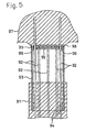
- the pile foundation structure of a third embodiment shown in Fig. 3 is described below.
- the third embodiment has an arrangement wherein the crushed-stone layer 17 for supporting the footing 18 as well as the mortar seat 16, so as to be movable in a horizontal direction, is laminated between the upper surface of the underground 11 and the lower surface of the footing 18.
- the pile foundation structure of the third embodiment ensures the same effect as the pile foundation structure of the second embodiment does, and the pile foundation structure is isolated from the underground 11, thereby exhibiting the earthquake avoidable property with the result that the seismic force and the lateral shaking of the upper structure are extremely reduced. Accordingly, the livability is improved, and the damage preventive effect is further enhanced.
- the second and third embodiments as mentioned above have the structure wherein the spherical-supporting-portion 13A of the head of the pile 12 is formed in a convex shape and the spherical-binding-portion 19A of the bottom of the footing 18 is formed in a concave shape, they may have the reversed structure wherein the spherical-supporting-portion 13A of the head of the pile 12 is formed in a concave shape and the spherical-binding-portion 19A of the bottom of the footing 18 is formed in a convex shape. Then, the latter structure can have the same action and effect as the former one.
- the pile foundation structure relates to a technique wherein a roller bearing structure or a pin structure is disposed between a supporting portion of a head of a pile for propagating a load of an upper structure to the underground depths and a binding portion of a bottom of a footing, thus preventing the pile and the footing from being damaged or destroyed owing to stress concentration applied to the binding portion of the pile head in applying a great external force such as an earthquake to the structure, and making it possible to reduce an amount of arrangement of reinforcement. Consequently, the technique can enhance the execution and realize the low-cost.
Landscapes
- Engineering & Computer Science (AREA)
- Structural Engineering (AREA)
- Environmental & Geological Engineering (AREA)
- Life Sciences & Earth Sciences (AREA)
- General Life Sciences & Earth Sciences (AREA)
- Mining & Mineral Resources (AREA)
- Paleontology (AREA)
- Civil Engineering (AREA)
- General Engineering & Computer Science (AREA)
- Foundations (AREA)
Claims (3)
- Eine auf Pfählen liegende Fundamentstruktur mit einem tragfähigen Boden (18), angeordnet auf einer Seite eines Pfahlkopfs (12) im Untergrund (11), enthaltend:Einen hochstehenden Trageteil (13), der auf dem Kopf des Pfahls (12) angeordnet ist, so daß er über eine obere Fläche des Untergrunds (11) hochsteht;einen mit Aussparungen versehenen Verbindungsteil (19) mit einer flachen oberen Fläche, angeordnet auf einem unteren Teil des tragfähigen Bodens (18), getrennt vom Pfahl (12), so daß er dem hochstehenden Trageteil (13) entspricht und einen größeren Durchmesser aufweist als der entsprechende hochstehende Trageteil (13); undein Gleitglied (22), das zwischen den flachen oberen Flächen des hochstehenden Trageteils (13) und den mit Aussparungen versehenen Verbindungsteilen (19) liegt;Metallteile (14, 20) entsprechend eingepaßt sind in eine äußere Fläche des Trageteils (13) des Kopfs des Pfahls (12) und in einer inneren Fläche des Verbindungsteils (19) des untersten Teils des tragfähigen Bodens (18) in einem Schließzustand;die Metallteile (14, 20) über Ankerglieder (15, 21) mit dem Kopf des Pfahls (12) bzw. dem untersten Teil des tragfähigen Bodens (18) integral verbunden sind;eine Schotterschicht (17) zum Tragen des tragfähigen Bodens (18), so daß sie horizontal bewegbar ist, ausgeformt ist zwischen einer unteren Fläche des tragfähigen Bodens (18) und der oberen Fläche des Untergrunds (11); undeine Abdichtverbindung (23) mit der Gleitfläche zwischen dem Trageteil (13) des Kopfs des Pfahls (12) und dem Verbindungsteil (19) des untersten Teils des tragfähigen Bodens (18) eingeschlossen ist.
- Eine auf Pfählen liegende Fundamentstruktur mit einem tragfähigen Boden (18), angeordnet auf einer Seite eines Pfahlkopfs (12) im Untergrund (11), enthaltend:dadurch gekennzeichnet, daßEinen kugelförmigen Trageteil (13A), der konvex oder konkav geformt ist, und auf dem Kopf des Pfahls (12) angeordnet ist, so daß er über eine obere Fläche des Untergrunds (11) hochsteht;einen kugelförmigen Verbindungsteil (19A), konvex oder konkav geformt, der auf einem unteren Teil des tragfähigen Bodens (18) angeordnet ist, getrennt vom Pfahl (12), so daß er dem kugelförmigen Trageteil (13A) entspricht,Metallteile (14A, 20A), die entsprechend in eine äußere Fläche des kugelförmigen Trageteils (23) des Kopfs des Pfahls (12) und eine Innenfläche des kugelförmigen Verbindungsteils (19A) des untersten Teils des tragfähigen Bodens (18) in einem Schließzustand eingepaßt sind, wobei die Metallteile (14A, 20A) mit dem Kopf des Pfahls (12) bzw. mit dem untersten Teil des tragfähigen Bodens integral verbunden sind;und ein Gleitglied (22A) zwischen einer äußeren Fläche des kugelförmigen Trageteils (13A) und einer inneren Fläche des kugelförmigen Verbindungsteils (19A) eingeschoben ist;der kugelförmige Verbindungsteil einen größeren Durchmesser aufweist als der entsprechende kugelförmige Trageteil (13A);eine Schotterschicht (17) zum Tragen des tragfähigen Bodens (18), so daß sie horizontal bewegbar ist, ausgeformt ist zwischen einer unteren Fläche des tragfähigen Bodens (18) und der oberen Fläche des Untergrunds (11); undeine Abdichtverbindung (23) mit der Gleitfläche zwischen dem kugelförmigen Trageteil (13A) des Kopfs des Pfahls (12) und dem kugelförmigen Verbindungsteil (19) des untersten Teils des tragfähigen Bodens (18) eingeschlossen ist.
- Eine Pfahlfundamentstruktur gemäß Anspruch 1 oder 2, in dem das Gleitglied (22, 22A) aus einem Material gefertigt ist, das selbst-schmierend ist.
Applications Claiming Priority (7)
| Application Number | Priority Date | Filing Date | Title |
|---|---|---|---|
| JP4705197 | 1997-02-14 | ||
| JP04705197A JP3455644B2 (ja) | 1997-02-14 | 1997-02-14 | 杭基礎構造 |
| JP4705097 | 1997-02-14 | ||
| JP04705097A JP3494199B2 (ja) | 1997-02-14 | 1997-02-14 | 杭基礎構造 |
| JP47050/97 | 1997-02-14 | ||
| JP47051/97 | 1997-02-14 | ||
| PCT/JP1998/000495 WO1998036130A1 (fr) | 1997-02-14 | 1998-02-05 | Structure de fondation sur pieux |
Publications (3)
| Publication Number | Publication Date |
|---|---|
| EP0894900A1 EP0894900A1 (de) | 1999-02-03 |
| EP0894900A4 EP0894900A4 (de) | 2000-05-03 |
| EP0894900B1 true EP0894900B1 (de) | 2003-06-18 |
Family
ID=26387200
Family Applications (1)
| Application Number | Title | Priority Date | Filing Date |
|---|---|---|---|
| EP98901533A Expired - Lifetime EP0894900B1 (de) | 1997-02-14 | 1998-02-05 | Pfahlgründungsstruktur |
Country Status (7)
| Country | Link |
|---|---|
| US (1) | US6102627A (de) |
| EP (1) | EP0894900B1 (de) |
| AU (1) | AU720244B2 (de) |
| DE (1) | DE69815604T2 (de) |
| NZ (1) | NZ332209A (de) |
| TW (1) | TW364931B (de) |
| WO (1) | WO1998036130A1 (de) |
Families Citing this family (14)
| Publication number | Priority date | Publication date | Assignee | Title |
|---|---|---|---|---|
| EP1069246A4 (de) * | 1999-02-03 | 2005-10-26 | Nippon Pillar Packing | Pfahlfundamentkonstruktion |
| US6324795B1 (en) | 1999-11-24 | 2001-12-04 | Ever-Level Foundation Systems, Inc. | Seismic isolation system between floor and foundation comprising a ball and socket joint and elastic or elastomeric element |
| US6554542B2 (en) * | 2000-04-10 | 2003-04-29 | Shimizu Construction Co., Ltd. | Stress transmission device, and structure and method of constructing the same |
| US6681538B1 (en) * | 2002-07-22 | 2004-01-27 | Skidmore, Owings & Merrill Llp | Seismic structural device |
| JP4467881B2 (ja) * | 2002-12-25 | 2010-05-26 | 極東興和株式会社 | 杭頭接合部の構造及び杭頭嵌装筒体 |
| US7308776B2 (en) * | 2003-04-04 | 2007-12-18 | Ray Robert H | Pole anchor footing system |
| US20070280787A1 (en) * | 2006-05-31 | 2007-12-06 | Gordon Snyder | Pier foundation system for manufactured building structures |
| JP5853741B2 (ja) * | 2012-02-06 | 2016-02-09 | 株式会社大林組 | 杭頭部接合構造、杭頭部接合方法、及びプレキャストコンクリート製のリング |
| CN102787534A (zh) * | 2012-09-02 | 2012-11-21 | 中铁二院工程集团有限责任公司 | 岩溶区轻型框架路基桩板结构构造 |
| US9109340B1 (en) * | 2014-06-04 | 2015-08-18 | James D Linn, Jr. | Pile-supported cable-reinforced building |
| JP6421009B2 (ja) * | 2014-10-02 | 2018-11-07 | 株式会社フジタ | 場所打ちコンクリート杭の杭頭半剛接合構造 |
| JP6710137B2 (ja) * | 2016-09-30 | 2020-06-17 | 株式会社熊谷組 | 杭頭接合部の構造 |
| CN107119677B (zh) * | 2017-06-08 | 2019-02-22 | 太原理工大学 | 一种管桩桩顶摩擦-剪切型耗能连接装置及其施工方法 |
| CN212412337U (zh) * | 2020-02-17 | 2021-01-26 | 番禺得意精密电子工业有限公司 | 电连接器 |
Family Cites Families (15)
| Publication number | Priority date | Publication date | Assignee | Title |
|---|---|---|---|---|
| FR1215536A (fr) * | 1957-05-09 | 1960-04-19 | Fondations spéciales destinées à protéger les immeubles contre les séismes | |
| US3105252A (en) * | 1960-08-24 | 1963-10-01 | Merriman Bros Inc | Slidable and rotatable bearing support |
| JPS5310764B2 (de) * | 1973-12-28 | 1978-04-17 | ||
| IN145684B (de) * | 1975-07-01 | 1979-04-21 | Spie Batignolles | |
| US4163621A (en) * | 1978-02-08 | 1979-08-07 | Tadayasu Higuchi | Method for forming a continuous footing with prefabricated footing blocks |
| DE2829309B2 (de) * | 1978-07-04 | 1980-08-07 | Glacier Gmbh Deva Werke | Verfahren zum Auskleiden der Konkav gewölbten Oberseite der Unterplatte eines Kippbewegungen eines Brückenüberbaus o.dgl. ermöglichenden Lagers und nach diesem Verfahren ausgekleidetes Lager |
| JPS59134230A (ja) * | 1983-01-18 | 1984-08-01 | Hideyuki Tada | 免震杭 |
| US4644714A (en) * | 1985-12-02 | 1987-02-24 | Earthquake Protection Systems, Inc. | Earthquake protective column support |
| JPS63289124A (ja) * | 1987-05-20 | 1988-11-25 | Tokyu Constr Co Ltd | 建築物の杭基礎に於ける杭頭ピン接合工法 |
| JPH01102124A (ja) | 1987-10-14 | 1989-04-19 | Kubota Ltd | コンクリート構造体支持構造 |
| US5014474A (en) * | 1989-04-24 | 1991-05-14 | Fyfe Edward R | System and apparatus for limiting the effect of vibrations between a structure and its foundation |
| US5081806A (en) * | 1989-07-25 | 1992-01-21 | Pommelet Yves M | Building structure foundation system |
| FR2658553A1 (fr) * | 1990-02-19 | 1991-08-23 | Colette Depoisier | Batiment anti-sismique. |
| GB2291076B (en) * | 1994-07-06 | 1997-07-02 | Darwen Bradbury Dennis | Fortifying buildings against earth tremors |
| JPH08120687A (ja) * | 1994-10-26 | 1996-05-14 | Taisei Corp | 杭頭支持構造及び杭鉄筋保持型枠 |
-
1998
- 1998-02-05 EP EP98901533A patent/EP0894900B1/de not_active Expired - Lifetime
- 1998-02-05 DE DE69815604T patent/DE69815604T2/de not_active Expired - Fee Related
- 1998-02-05 US US09/147,118 patent/US6102627A/en not_active Expired - Fee Related
- 1998-02-05 NZ NZ332209A patent/NZ332209A/xx unknown
- 1998-02-05 AU AU57805/98A patent/AU720244B2/en not_active Ceased
- 1998-02-05 WO PCT/JP1998/000495 patent/WO1998036130A1/ja active IP Right Grant
- 1998-02-07 TW TW087101649A patent/TW364931B/zh not_active IP Right Cessation
Also Published As
| Publication number | Publication date |
|---|---|
| WO1998036130A1 (fr) | 1998-08-20 |
| AU5780598A (en) | 1998-09-08 |
| NZ332209A (en) | 2000-05-26 |
| US6102627A (en) | 2000-08-15 |
| AU720244B2 (en) | 2000-05-25 |
| DE69815604T2 (de) | 2004-04-29 |
| EP0894900A4 (de) | 2000-05-03 |
| DE69815604D1 (de) | 2003-07-24 |
| TW364931B (en) | 1999-07-21 |
| EP0894900A1 (de) | 1999-02-03 |
Similar Documents
| Publication | Publication Date | Title |
|---|---|---|
| US6474030B1 (en) | Pile foundation structure | |
| EP0894900B1 (de) | Pfahlgründungsstruktur | |
| US5215382A (en) | Isolation bearing for structures with transverse anchor rods | |
| JP2715261B2 (ja) | 液状化地盤用杭及び同杭による杭の水平抵抗増強方法 | |
| US8196368B2 (en) | Ductile seismic shear key | |
| JP3855198B2 (ja) | 杭基礎構造物の耐震補強構造 | |
| US5850653A (en) | Pre-cast concrete decking for load supporting structures | |
| JP3455644B2 (ja) | 杭基礎構造 | |
| JPH10227039A (ja) | 杭基礎構造 | |
| JPH11172810A (ja) | 耐震壁及び耐震補強構造 | |
| JPH09256390A (ja) | 免震杭基礎 | |
| JP6275314B1 (ja) | 橋梁の耐震補強構造 | |
| JP3671153B2 (ja) | 杭基礎構造 | |
| JP4208950B1 (ja) | 建物の耐震基礎構造 | |
| JP2001020558A (ja) | 建築物の基礎免震構造 | |
| JP3165063B2 (ja) | 耐震基礎構造 | |
| JP3349473B2 (ja) | 耐震貯水構造体 | |
| JP4129663B2 (ja) | 地盤改良体を用いた建物 | |
| JP2001234549A (ja) | 杭と基礎との接合構造 | |
| RU2188907C1 (ru) | Фундамент сейсмостойкого здания на колоннаде, расположенной в подвальном этаже | |
| JPH0988089A (ja) | 減震基礎構造 | |
| JPH11117320A (ja) | 免震建物の基礎 | |
| JP2022150755A (ja) | 橋桁の変位制御構造 | |
| JP3511001B2 (ja) | 杭基礎における杭頭接合構造 | |
| JPH1181341A (ja) | 耐震杭工法 |
Legal Events
| Date | Code | Title | Description |
|---|---|---|---|
| PUAI | Public reference made under article 153(3) epc to a published international application that has entered the european phase |
Free format text: ORIGINAL CODE: 0009012 |
|
| 17P | Request for examination filed |
Effective date: 19980930 |
|
| AK | Designated contracting states |
Kind code of ref document: A1 Designated state(s): DE FR GB |
|
| A4 | Supplementary search report drawn up and despatched |
Effective date: 20000322 |
|
| AK | Designated contracting states |
Kind code of ref document: A4 Designated state(s): DE FR GB |
|
| RIC1 | Information provided on ipc code assigned before grant |
Free format text: 7E 02D 27/12 A, 7E 02D 27/34 B, 7E 04H 9/02 B |
|
| 17Q | First examination report despatched |
Effective date: 20020225 |
|
| GRAH | Despatch of communication of intention to grant a patent |
Free format text: ORIGINAL CODE: EPIDOS IGRA |
|
| GRAH | Despatch of communication of intention to grant a patent |
Free format text: ORIGINAL CODE: EPIDOS IGRA |
|
| GRAA | (expected) grant |
Free format text: ORIGINAL CODE: 0009210 |
|
| AK | Designated contracting states |
Designated state(s): DE FR GB |
|
| REG | Reference to a national code |
Ref country code: GB Ref legal event code: FG4D |
|
| REF | Corresponds to: |
Ref document number: 69815604 Country of ref document: DE Date of ref document: 20030724 Kind code of ref document: P |
|
| ET | Fr: translation filed | ||
| PLBE | No opposition filed within time limit |
Free format text: ORIGINAL CODE: 0009261 |
|
| STAA | Information on the status of an ep patent application or granted ep patent |
Free format text: STATUS: NO OPPOSITION FILED WITHIN TIME LIMIT |
|
| 26N | No opposition filed |
Effective date: 20040319 |
|
| PGFP | Annual fee paid to national office [announced via postgrant information from national office to epo] |
Ref country code: DE Payment date: 20060214 Year of fee payment: 9 |
|
| PGFP | Annual fee paid to national office [announced via postgrant information from national office to epo] |
Ref country code: FR Payment date: 20060216 Year of fee payment: 9 |
|
| GBPC | Gb: european patent ceased through non-payment of renewal fee |
Effective date: 20070205 |
|
| REG | Reference to a national code |
Ref country code: FR Ref legal event code: ST Effective date: 20071030 |
|
| PG25 | Lapsed in a contracting state [announced via postgrant information from national office to epo] |
Ref country code: DE Free format text: LAPSE BECAUSE OF NON-PAYMENT OF DUE FEES Effective date: 20070901 |
|
| PG25 | Lapsed in a contracting state [announced via postgrant information from national office to epo] |
Ref country code: GB Free format text: LAPSE BECAUSE OF NON-PAYMENT OF DUE FEES Effective date: 20070205 Ref country code: FR Free format text: LAPSE BECAUSE OF NON-PAYMENT OF DUE FEES Effective date: 20070228 |
|
| PGFP | Annual fee paid to national office [announced via postgrant information from national office to epo] |
Ref country code: GB Payment date: 20060221 Year of fee payment: 9 |