EP0891059B1 - Folgeschätzung für Teilantwortkanäle - Google Patents
Folgeschätzung für Teilantwortkanäle Download PDFInfo
- Publication number
- EP0891059B1 EP0891059B1 EP98301315A EP98301315A EP0891059B1 EP 0891059 B1 EP0891059 B1 EP 0891059B1 EP 98301315 A EP98301315 A EP 98301315A EP 98301315 A EP98301315 A EP 98301315A EP 0891059 B1 EP0891059 B1 EP 0891059B1
- Authority
- EP
- European Patent Office
- Prior art keywords
- signal
- channel
- output
- decoded data
- characteristic
- Prior art date
- Legal status (The legal status is an assumption and is not a legal conclusion. Google has not performed a legal analysis and makes no representation as to the accuracy of the status listed.)
- Expired - Lifetime
Links
Images


Classifications
-
- H—ELECTRICITY
- H03—ELECTRONIC CIRCUITRY
- H03M—CODING; DECODING; CODE CONVERSION IN GENERAL
- H03M13/00—Coding, decoding or code conversion, for error detection or error correction; Coding theory basic assumptions; Coding bounds; Error probability evaluation methods; Channel models; Simulation or testing of codes
-
- G—PHYSICS
- G11—INFORMATION STORAGE
- G11B—INFORMATION STORAGE BASED ON RELATIVE MOVEMENT BETWEEN RECORD CARRIER AND TRANSDUCER
- G11B20/00—Signal processing not specific to the method of recording or reproducing; Circuits therefor
- G11B20/10—Digital recording or reproducing
- G11B20/10009—Improvement or modification of read or write signals
- G11B20/10046—Improvement or modification of read or write signals filtering or equalising, e.g. setting the tap weights of an FIR filter
- G11B20/10055—Improvement or modification of read or write signals filtering or equalising, e.g. setting the tap weights of an FIR filter using partial response filtering when writing the signal to the medium or reading it therefrom
- G11B20/10175—PR4, PR(1,0,-1), i.e. partial response class 4, polynomial (1+D)(1-D)=(1-D2)
-
- G—PHYSICS
- G11—INFORMATION STORAGE
- G11B—INFORMATION STORAGE BASED ON RELATIVE MOVEMENT BETWEEN RECORD CARRIER AND TRANSDUCER
- G11B20/00—Signal processing not specific to the method of recording or reproducing; Circuits therefor
- G11B20/10—Digital recording or reproducing
- G11B20/10009—Improvement or modification of read or write signals
- G11B20/10046—Improvement or modification of read or write signals filtering or equalising, e.g. setting the tap weights of an FIR filter
- G11B20/10055—Improvement or modification of read or write signals filtering or equalising, e.g. setting the tap weights of an FIR filter using partial response filtering when writing the signal to the medium or reading it therefrom
-
- G—PHYSICS
- G11—INFORMATION STORAGE
- G11B—INFORMATION STORAGE BASED ON RELATIVE MOVEMENT BETWEEN RECORD CARRIER AND TRANSDUCER
- G11B20/00—Signal processing not specific to the method of recording or reproducing; Circuits therefor
- G11B20/10—Digital recording or reproducing
- G11B20/10009—Improvement or modification of read or write signals
- G11B20/10268—Improvement or modification of read or write signals bit detection or demodulation methods
- G11B20/10287—Improvement or modification of read or write signals bit detection or demodulation methods using probabilistic methods, e.g. maximum likelihood detectors
- G11B20/10296—Improvement or modification of read or write signals bit detection or demodulation methods using probabilistic methods, e.g. maximum likelihood detectors using the Viterbi algorithm
-
- H—ELECTRICITY
- H04—ELECTRIC COMMUNICATION TECHNIQUE
- H04L—TRANSMISSION OF DIGITAL INFORMATION, e.g. TELEGRAPHIC COMMUNICATION
- H04L25/00—Baseband systems
- H04L25/38—Synchronous or start-stop systems, e.g. for Baudot code
- H04L25/40—Transmitting circuits; Receiving circuits
- H04L25/49—Transmitting circuits; Receiving circuits using code conversion at the transmitter; using predistortion; using insertion of idle bits for obtaining a desired frequency spectrum; using three or more amplitude levels ; Baseband coding techniques specific to data transmission systems
- H04L25/497—Transmitting circuits; Receiving circuits using code conversion at the transmitter; using predistortion; using insertion of idle bits for obtaining a desired frequency spectrum; using three or more amplitude levels ; Baseband coding techniques specific to data transmission systems by correlative coding, e.g. partial response coding or echo modulation coding transmitters and receivers for partial response systems
-
- H—ELECTRICITY
- H04—ELECTRIC COMMUNICATION TECHNIQUE
- H04L—TRANSMISSION OF DIGITAL INFORMATION, e.g. TELEGRAPHIC COMMUNICATION
- H04L25/00—Baseband systems
- H04L25/02—Details ; arrangements for supplying electrical power along data transmission lines
- H04L25/03—Shaping networks in transmitter or receiver, e.g. adaptive shaping networks
- H04L25/03006—Arrangements for removing intersymbol interference
- H04L2025/0335—Arrangements for removing intersymbol interference characterised by the type of transmission
- H04L2025/03356—Baseband transmission
- H04L2025/03369—Partial response
-
- H—ELECTRICITY
- H04—ELECTRIC COMMUNICATION TECHNIQUE
- H04L—TRANSMISSION OF DIGITAL INFORMATION, e.g. TELEGRAPHIC COMMUNICATION
- H04L25/00—Baseband systems
- H04L25/02—Details ; arrangements for supplying electrical power along data transmission lines
- H04L25/03—Shaping networks in transmitter or receiver, e.g. adaptive shaping networks
- H04L25/03006—Arrangements for removing intersymbol interference
- H04L25/03178—Arrangements involving sequence estimation techniques
Definitions
- the present invention relates to data decoding, and more particularly, to a data decoding apparatus which can greatly reduce hardware size by decoding data using a maximum likelihood decoder comprised of a channel in a digital recording/reproducing apparatus having a partial-response class 4 (PR4) or extended-partial response class 4 (E n PR4) channel, and a method therefor.
- PR4 partial-response class 4
- E n PR4 extended-partial response class 4
- PRML Partial Response Maximum Likelihood
- Figure 1 is a block diagram of a digital video cassette recorder (DVCR) having a PR4(1, 0, -1) channel.
- a Non-Return-to-Zero-Inversion (NRZI) converter 102 converts an input signal into an NRZI code represented by 1 or -1.
- a precoder 108 converts the NRZI code into an interleave NRZI code.
- the NRZI converter 102 and the precoder 108 are constructed to have a 1/1+D characteristic, where D refers to a 1-bit delay (unit delay) of recording data.
- an input signal and a signal delayed by a delay element 106 or 112 are XOR-performed in an XOR gate 104 or 110 to be output and the XOR-performed signal is fed back to the delay element.
- a reproducing amplifier 116 of a reproducing system amplifies a reproduction signal through a channel 114 having a 1-D characteristic, i.e., a differential characteristic. At this time, the amplified reproduction signal is a PR(+1, -1) mode signal.
- An equalizer 118 compensates for waveform distortion and amplitude distortion of the signal amplified in the reproducing amplifier 116.
- the channel demodulator 120 includes an adder 124 and a delay 122 and has the 1+D characteristic inverse to the 1/1+D characteristic of the precoder 108, so that noise characteristics are improved and the aperture ratio of an eye pattern is decreased.
- a timing detector 140 detects timing of the reproduction signal equalized in the equalizer 118 using an internally installed phase locked loop (PLL) and outputs driving clocks required for the equalizer 118 and the maximum likelihood decoder 126.
- PLL phase locked loop
- the reproducing system requires four (2 2 ) 4-state Viterbi decoders.
- two (1+D) channels are interleaved, 2-state Viterbi decoders are necessary.
- the maximum likelihood decoder 126 shown in Figure 1 is constructed such that two state detectors 130 and 132 and two Viterbi decoders 134 and 136, performing the same operation, are connected in parallel, respectively.
- a demultiplexer 128 and a multiplexer 138 operate according to a driving clock output from a timing detector 140. Decoded data is output from the multiplexer 138.
- the reason why the state detectors and the Viterbi decoders are constructed by two channels is to apply a Viterbi algorithm such that PR4(+1, 0, -1) data output from a channel demodulator 120 is converted into PR(+1, -1) data, to satisfy conditions that "0" or "-1” is read out after "+1” and "+1” is never read out and that "0” or "+1” is read out after "-1" and "-1” is never read out.
- the DVCR having the PR4 channel shown in Figure 1 may perform decoding of data using the maximum likelihood decoding algorithm such as Viterbi decoding algorithm, which is referred to as a PRML system.
- the maximum likelihood decoding algorithm such as Viterbi decoding algorithm
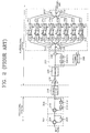
- FIG 2 is a block diagram of a digital recording/reproducing system having an EPR4(1, 1, -1, -1) channel having the simplest structure among E n PR4 channels, and detailed explanation of the same elements corresponding to those shown in Figure 1 will be omitted herein.
- a typical example of the digital recording/reproducing apparatus having the EPR4 channel is a hard disk driver.
- a precoder 208 includes one more delay 214 to have a 1/(1+D) 2 characteristic, in which the precoder 208 is called an EPR4(1, 1, -1, -1) precoder. Since a recording system includes three delays 206, 212 and 214, a reproducing system requires 2 3 8-state Viterbi decoders 250 through 264 and eight state detectors 234 through 248. Also, a channel demodulator 222 includes an adder 228 and two delays 224 and 226 to have a (1+D) 2 characteristic, in correspondence with the precoder 208 having the 1/(1+D) 2 characteristic.
- SD refers to a state detector
- VD refers to a Viterbi decoder
- a driving clock CK output from a timing detector 268 is supplied to a demultiplexer 232, first through eighth Viterbi decoders 250 through 264 and a multiplexer 266.
- Reference numerals 218 and 220 denote an amplifier and an equalizer, respectively.
- Figure 3 is a conceptual block diagram of a digital recording/reproducing apparatus having an E n PR4 channel.
- a channel demodulator 312 corresponding to a precoder 304 having a 1/(1+D) n+1 characteristic is constructed to have a (1+D) n+1 characteristic.
- a maximum likelihood decoder 314 includes 2 n+2 Viterbi decoders, 2 n+2 state detectors, a demultiplexer for demultiplexing outputs of the channel demodulator 312 to output to the 2 n+2 state detectors, and a multiplexer for multiplexing outputs of the 2 n+2 Viterbi decoders to output decoded data.
- each 2 n+2 of the state detectors and the Viterbi decoders are constructed in parallel.
- Demodulated data are demultiplexed into 2 n+2 channels, independently decoded by the Viterbi decoders constructed to correspond to the respective channels and then multiplexed again.
- This is for applying a Viterbi algorithm by separating the E n PR4 signals of the channel demodulator 312 into PR(1, -1) signals to satisfy conditions that "0" or "-1" is read after "+1" and "+1” is never read and that "0" or "+1” is read after "-1" and "-1” is never read.
- an EPR4 system and an E 2 PR4 system have greater noise resistance noise than a PR4 system and an EPR4 system, respectively, and signal bands thereof are reduced.
- the recording density of a channel band is increased.
- the aperture ratio of an eye pattern is decreased and the hardware becomes complex.
- a conventional PR4 system requires four maximum likelihood decoders constructed in parallel (two for a DVCR), an EPR4 system requires eight maximum likelihood decoders constructed in parallel, and an E n PR4 system requires 2 n+2 maximum likelihood decoders constructed in parallel.
- the hardware burden becomes sharply increased.
- WO 97/16011 describes the addressing of data tracks in a disk drive having a partial response, maximum likelihood synchronous sampled detection channel.
- the described system has a PR4 channel with 1/(1+D) characteristic, with the data decoder comprising a Viterbi decoder and a channel demodulator having a (1+D) characteristic.
- US 5,448,424 describes an automatic gain control circuit for use with magnetic recording and reproducing apparatus, which controls an amplitude value in accordance with a set value.
- a data decoding apparatus for a system having a PR4 channel including a precoder having a 1/(1+D) characteristic, the apparatus comprising: a maximum likelihood decoder comprised of a channel, for maximum-likelihood-decoding a PR(+1, -1) signal received through said channel to output maximum-likelihood-decoded data; and a channel demodulator having a (1+D) characteristic which is a reverse characteristic of said precoder, for channel-demodulating said maximum-likelihood-decoded data to output decoded data, wherein said maximum likelihood decoder comprises: a state detector for detecting positive and negative state values of the PR(+1, -1) signal according to positive and negative threshold values varying according to the PR(+1, -1) signal received through said channel; and a Viterbi decoder for receiving the positive and negative state values and Viterbi-decoding the same.
- the apparatus further comprises a pre-filter having a (1+D) characteristic, for converting the PR(+1, - 1) signal received through said channel into a PR4(+1, 0, - 1) signal; and a reverse pre-filter having a 1/(1+D) characteristic, for converting the PR4(+1,0,-1) signal received through said channel into a PR(+1,-1) signal again; wherein the maximum likelihood decoder (540, 550) is for maximum-likelihood-decoding the PR(+1, -1) signal output from said reverse pre-filter.
- said pre-filter comprises: a first delay (D) for delaying the PR(+1, -1) signal received through said channel by a unit value to output the delayed signal; and a first adder for adding the delayed signal to the PR(+1, -1) signal received through said channel to output a first addition signal of a PR4(+1, 0, -1) mode.
- D first delay
- said pre-filter comprises: a first delay (D) for delaying the PR(+1, -1) signal received through said channel by a unit value to output the delayed signal; and a first adder for adding the delayed signal to the PR(+1, -1) signal received through said channel to output a first addition signal of a PR4(+1, 0, -1) mode.
- said reverse pre-filter comprises: a subtractor for subtracting the positive state value from the negative state value; a second delay for delaying the output of said subtractor by a unit value to output a feed-back signal; and a second adder for adding the first addition signal to the feed-back signal to output a PR(+1, - 1) signal.
- said channel demodulator comprises: a D-flipflop for unit-delaying the maximum-likelihood decoded data by a unit value; and an XOR logic circuit for performing an XOR operation on the maximum-likelihood decoded data and the output of said D-flipflop.
- the apparatus further comprises: a sample and hold circuit for sampling and holding the PR(+1, -1) signal received through said channel; and a timing detector for detecting the timing of the PR(+1, -1) signal received through said channel to generate driving clock of said sample & hold circuit, said maximum likelihood decoder and said channel demodulator.
- the apparatus further comprises: an analog-to-digital (A/D) converter for converting the PR(+1, -1) signal received through said channel into digital data; and a timing detector for detecting the timing of the PR(+1, - 1) signal received through said channel to generate driving clock of said sample & hold circuit, said maximum likelihood decoder and said channel demodulator.
- A/D analog-to-digital
- the apparatus further comprises: a unit having n+1 sets connected in series, each set comprising a pre-filter, a state detector and a reverse pre-filter, each set having a pre-filter having a (1+D) characteristic, for converting the PR(+1, -1) signal received through said channel into a PR4(+1, 0, -1) signal, and a reverse pre-filter having a 1/(1+D) characteristic, for feed-back receiving the positive and negative state values, converting again the PR4(+1, 0, -1) signal into the PR(+1, - 1) signal and outputting the converted signal to said state detector; the channel demodulator comprising first and second channel demodulators, the first channel demodulator having said (1+D) characteristic which is a reverse characteristic of said precoder, for channel-demodulating the Viterbi-decoded data to output decoded data of a PR4 mode; and the second channel demodulator having a (1+D) n characteristic, for channel-demodulating the output of said first channel
- said first channel demodulator comprises: a unit delay for delaying the maximum-likelihood decoded data by a unit value; and an XOR logic circuit for performing an XOR operation on the maximum-likelihood decoded data and the output of said unit delay.
- said second channel demodulator comprises: n delays serially connected for n-bit delaying the output of said first channel demodulator; and an XOR logic circuit for performing an XOR operation on the outputs of said first channel demodulator and the outputs of said n delays.
- a data decoding apparatus for a system having an E n PR4 channel including a precoder having a 1/(1+D) n+1 characteristic
- the apparatus comprising: a unit having n+1 sets connected in series, each set comprising a pre-filter, a state detector and a reverse pre-filter, each set having a pre-filter having a (1+D) characteristic, for converting the PR(+1, -1) signal received through said channel into a PR4(+1, 0, -1) signal, a state detector for detecting positive and negative state values of the PR(+1, -1) signal depending on positive and negative threshold values varying according to the PR(+1, -1), and a reverse pre-filter for feed-back receiving the positive and negative state values, converting again the PR4(+1, 0, -1) signal into the PR(+1, -1) signal and outputting the converted signal to said state detector; a Viterbi decoder comprised of a channel, for Viterbi
- said channel demodulator comprises: n+1 delays connected in series, for (n+1) bit-delaying the maximum-likelihood decoded data; and an XOR logic circuit for performing an XOR operation on maximum-likelihood decoded data from the Viterbi decoder and the outputs of said n+1 delays.
- the first pre-filter of said unit comprises: a first delay for delaying the PR(+1, -1) signal received through said channel by a unit value to output a first delayed signal; and an adder for adding the PR(+1, -1) signal received through said channel to said delayed signal to output a first addition signal of a PR4(+1, 0, -1) mode
- each of the second through (n+1)th pre-filters comprises: a delay for delaying the PR(+1, -1) signal output from the directly previous reverse pre-filter by a unit period to output a delayed signal; and an adder for adding the PR(+1, -1) signal output from the directly previous reverse pre-filter to said delayed signal to output a PR4(+1, 0, -1) signal.
- each of said reverse pre-filters comprises: a subtractor for subtracting the positive state value from the negative state value output from said state detector; a second delay or delaying the output of said subtractor by a unit value to output a feed-back signal; and a second adder for adding the output signal of said precoder to the feed-back signal.
- the apparatus further comprises: a sample and hold circuit for sampling and holding the PR(+1, -1) signal received through said channel; and a timing detector for detecting the timing of the PR(+1, -1) signal received through said channel to generate driving clock of said sample & hold circuit, said Viterbi decoder and said channel demodulator.
- the apparatus further comprises: an analog-to-digital (A/D) converter for converting the PR(+1, -1) signal received through said channel into digital data; and a timing detector for detecting the timing of the PR(+1, - 1) signal received through said channel to generate driving clock of said sample & hold circuit, said Viterbi decoder and said channel demodulator.
- A/D analog-to-digital
- a data decoding method for use in apparatus having a PR4 channel including a precoder having a 1/(1+D) characteristic, said data decoding method comprising the steps of: (a) directly maximum-likelihood-decoding a PR(+1, -1) signal received through said channel to output maximum-likelihood-decoded data; and (b) unit-bit delaying said maximum-likelihood-decoded data to have a (1+D) characteristic which is a reverse characteristic of said precoder, adding the delayed data to the maximum-likelihood decoded data to output decoded data, wherein said step (a) comprises the steps of: (a1) detecting positive and negative state values of the PR(+1, -1) signal depending on positive and negative threshold values varying according to the PR(+1, -1) signal received through said channel; and (a2) receiving the positive and negative state values and Viterbi-decoding the same.
- a data decoding method for use in apparatus having a PR4 channel including a precoder having a 1/(1+D) characteristic, said data decoding method comprising the steps of: (a) unit-bit delaying a PR(+1, -1) signal received through said channel to have a (1+D) characteristic, adding the delayed signal to the PR(+1, -1) signal to convert again the result into the PR4(+1, 0, -1) signal; (b) adding the PR4(+1, 0, -1) signal to a feed-back signal to have a (1+D) characteristic, to convert again the result into the PR(+1, -1) signal; (c) detecting positive and negative state values of the PR(+1, -1) signal depending on positive and negative threshold values varying according to the PR(+1, -1) signal converted in said (b) step, and outputting the feed-back signal obtained by subtracting the positive state value from the negative state value; (d) receiving the positive and negative state values and Viterb
- step (d) comprises Viterbi-decoding the PR(+1, -1) signal output after repeating said (a) through (c) steps (n+1)- times, and outputting the Viterbi-decoded data
- step (e) comprises unit-bit delaying the Viterbi-decoded data to have a (1+D) characteristic which is a reverse characteristic of said precoder, and adding the delayed data to the Viterbi-decoded data to output a PR4-mode decoded data
- the method further comprising the steps of: (f) n-bit delaying the PR4-mode decoded data to have a (1+D) n characteristic, and adding the n-bit delayed data to the PR4-mode decoded data to output E n PR4-mode decoded data; and (g) selecting one of the PR4-mode decoded data and the E n PR4-mode decoded data according to
- a data decoding method for use in apparatus having an E n PR4 channel including a precoder having a 1/(1+D) n+1 characteristic, said data decoding method comprising the steps of: (a) unit-bit delaying a PR(+1, -1) signal received through said channel to have a (1+D) characteristic, adding the delayed signal to the PR(+1, -1) signal to convert the result into a PR4(+1, 0, - 1) signal; (b) adding the PR4(+1, 0, -1) signal to a feed-back signal to have a (1+D) characteristic, to convert again the result into the PR(+1, -1) signal; (c) detecting positive and negative state values of the PR(+1, -1) signal depending on positive and negative threshold values varying according to the PR(+1, -1) signal converted in said (b) step, and outputting the feed-back signal obtained by substracting the positive state value from the negative state value; (d) repeating said (a) unit-bit delaying a PR(+1,
- a sample and hold circuit (SAMPLE & HOLD 410) samples and holds an equalized signal output from an equalizer (not shown).
- the output state of the SAMPLE & HOLD 410 retains an analog level at the moment when sampling is performed according to driving clocks generated in a timing detector 450, not a digital level "1" or "0.”
- a peak detector 420 is an example of an implemented state detector.
- a positive peak value detector 423 and a negative peak value detector 425 are examples of a positive state value detector and a negative state value detector, respectively.
- a positive peak value detecting threshold value (to be referred to as a positive threshold value hereinafter) and a negative peak value detecting threshold value (to be referred to as a negative threshold value hereinafter) are set in conjunction with a signal Vs output from the SAMPLE & HOLD 410 of the peak detector 420.
- the respective threshold values are controlled by peak detection values having opposite polarities to each other.
- a positive peak value (Hn) and a negative peak value (Ln) are detected from the signal equalized according to the set threshold values.
- a demultiplexer and an amplifier (DEMUX & AMP 421 of the peak detector 420 detects only positive (+) values from the signal Vs output from the SAMPLE & HOLD 410 to output a positive signal Va amplified in a predetermined level to a first automatic threshold controller (ATC1) 422 and the positive peak value detector 423. Also, the DEMUX & AMP 421 detects only negative (-) values from the signal Vs output from the SAMPLE & HOLD 410 to output a negative signal Vb amplified in a predetermined level to a second automatic threshold controller (ATC2) 424 and the negative peak value detector 425.
- ATC1 first automatic threshold controller
- ATC2 second automatic threshold controller
- the ATC1 422 automatically sets a threshold value Vra of "+1" for detecting a positive peak value in conjunction with the amplified positive signal Va output from the DEMUX & AMP 421, and resets the threshold value Vrb of "-1" to a predetermined value at the time when a negative peak value of an active state (here, logic "1") is detected from the negative peak value detector 425.
- the positive peak value detector 423 compares the amplified positive signal Va with the positive threshold value set by the ATC1 422 to then output a positive peak value Hn corresponding to the amplified positive signal Va and feed back the positive peak value Hn to the ATC2 424.
- the ATC2 424 automatically sets a threshold value Vrb of "-1" for detecting a negative peak value in conjunction with the amplified negative signal Vb output from the DEMUX & AMP 421, and resets the threshold value Vrb of "-1" to a predetermined value at the time when a positive peak value of an active state (here, logic "1") is detected from the positive peak value detector 423.
- the negative peak value detector 425 compares the amplified negative signal Vb with the negative threshold value set by the ATC2 424 to then output a negative peak value Ln corresponding to the amplified negative signal Vb and feed back the negative peak value Ln to the ATC1 422.
- the positive peak value Hn of the positive peak value detector 423 and the negative peak value Ln of the negative peak value detector 425 are digital data.
- the peak detector 420 can employ any configuration that positive and negative values of an input signal are detected by means of a threshold value.
- a peak detector using ATC is disclosed in an article entitled “Signal processing method PRML, achieving large capacity memory device of the next generation.” in Japan Nikkei Electronics No. 599, pp. 72-79, January 1994 by Imai and Miyaki et al.
- the peak detector disclosed in the above article detects a positive peak value of an input signal since positive and negative peak values of the signal basically correspond to matrices in the case of a binary state number, and makes a provision for detecting the next positive peak value by retaining the detected value for being used as a new threshold value and simultaneously renews the threshold value for detecting a negative peak value.
- the peak detector detects a negative peak value of an input signal, and makes a provision for detecting the next negative peak value by retaining the detected value for being used as a new threshold value and renews the threshold value for detecting a positive peak value.
- this peak detector cannot renew opposite threshold values completely at a desired time. Therefore, there has been proposed a peak detector shown in Figure 4, for better Viterbi decoding efficiency.
- ATC means that threshold values are renewed in conjunction with the input signal.
- a Viterbi decoder 430 which is a PR(+1, -1) Viterbi decoder receives and Viterbi-decodes the positive peak value Hn and the negative peak value Ln detected from the peak detector 420.
- the Viterbi decoder 430 can take any kind of a Viterbi decoder using a Viterbi algorithm. Specifically, a Viterbi decoder which does not require an analog-to-digital (A/D) converter can be used.
- A/D analog-to-digital
- the analog Viterbi decoder has a simple circuit, compared to a conventional one, which minimizes the area of an integrated circuit, thereby reducing the cost and power consumption.
- this decoder is suitable for a small-sized product necessitating low electricity such as a digital video camcorder.
- the data decoding apparatus shown in Figure 4 adopts an analog Viterbi decoder.
- the SAMPLE & HOLD 410 must be replaced with an A/D converter.
- a channel demodulator 440 having a (1+D) characteristic demodulates Viterbi-decoded data and outputs finally decoded data. Since the output of the Viterbi decoder 430 is digital data, the channel demodulator 440 may be constructed by a D-flipflop by which a delay 442 operates according to driving clock generated in a timing detector 450. An adder 441 may be constructed by an exclusive OR gate. The timing detector 450 detects timing of an equalized reproduction signal to output driving clock necessary for the SAMPLE & HOLD 410, the Viterbi decoder 430 and the channel demodulator 440.
- the data decoding apparatus shown in Figure 4 Viterbi-decodes the PR(+1, -1) signal whose channel is demodulated without decoding the PR4(+1, 0, -1) signal demodulated by the channel demodulator, in contrast with that shown in Figure 1.
- the peak detector 420 and the Viterbi decoder 430 can be comprised of only a single channel.
- the output of the Viterbi decoder 430 is demodulated by the channel demodulator 440 having the (1+D) characteristic and then finally decoded data is output.
- the data decoding apparatus shown in Figure 4 detects peaks prior to channel demodulation using the (1+D) characteristic, when much noise is overlapped with the reproduction signal, errors in the positive peak value Hn and the negative peak value Ln output from the peak detector 420 are increased, thereby lowering the overall performance of the data decoding apparatus. Therefore, the data decoding apparatus shown in Figure 4 can be adopted for a recording/reproducing apparatus having a PR4 channel having good noise tolerance. Particularly, if the noise overlapped with the reproduction signal is a negligible level that cannot affect the desired performance of the decoded data, the apparatus shown in Figure 4 will have remarkable competitiveness in view of implementation simplicity and cost.
- the level of the noise overlapped with the reproduction signal is not usually negligible. It is important to decrease the noise level in determining the data decoding efficiency.
- the main causes of noise generation include the property of tape particles, head impedance and initial bias resistance of a reproducing amplifier. Also, since the Viterbi decoder is reached after passing through various processors including a reproducing head, reproducing amplifier and equalizer, the spectrum of the input signal varies.
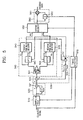
- Figure 5 shows a data decoding apparatus comprised of one channel state detector and Viterbi decoder, capable of solving such a noise problem.
- a SAMPLE & HOLD 510, a peak detector 540 as an example of a state detector, a channel demodulator 560 and a timing detector 570 shown in Figure 5 are the same as the corresponding elements shown in Figure 4, and the detailed operation thereof will not be explained herein.
- a pre-filter 520 having a (1+D) characteristic delays the output signal Vs of the SAMPLE & HOLD 510 by a period D corresponding to one bit of recorded data and adds the delayed signal with the output signal Vs of the SAMPLE & HOLD 510 in an adder 521. Since the pre-filter 520 serves as a low-pass filter, the noise characteristic is improved, but the aperture ratio of an eye pattern is decreased. The pre-filter 520 converts a PR(+1, -1) signal into a PR4(+1, 0, -1) signal.
- An inverse pre-filter 530 has a 1/(1+D) characteristic which is an inverted characteristic of the pre-filter 520.
- a subtractor 531 subtracts a positive peak value Hn output from a positive peak value detector 543 from a negative peak value Ln output from a negative peak value detector 545 in a peak detector 540.
- the subtraction result is delayed by a delay 532 by a period D corresponding to one bit of recorded data and then a feed-back signal Fs is fed back to an adder 533.
- the adder 533 adds the output of the pre-filter 520 and the feed-back signal Fs to output the result to the peak detector 540. At this time, the feed-back signal Fs is a signal having a negative value.
- the PR4(+1, 0, -1) signal output from the pre-filter 520 is again converted into the original PR(+1, -1) signal according to a 1/(1+D) characteristic of the inverse pre-filter 530 to allow data decoding using only the peak detector 540 and the Viterbi decoder 550.
- the noise level is almost the same as that in the conventional PR4 system having a channel demodulator in front of the state detectors and the Viterbi decoders.
- the data decoding apparatus shown in Figure 5 can obtain a reproduction output corresponding to a noise characteristic of the PR4(+1, 0, -1) system and corresponding to an aperture ratio of the PR(+1, -1) system.
- the performance of the Viterbi decoder is improved and the structure thereof is simplified, thereby becoming sufficiently competitive.
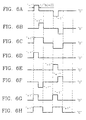
- Figures 6A through 6H are operational waveform diagrams of the data decoding apparatus shown in Figure 5.
- Figure 6A shows a waveform of an output signal Vs of the SAMPLE & HOLD 510
- Figure 6B shows a waveform of a signal obtained by delaying the output signal Vs of the SAMPLE & HOLD 510 by a one-bit period D of recorded data by the delay 522 of the pre-filter 520.
- Figure 6C shows a waveform of an output of the adder 521 of the pre-filter 520
- Figure 6D shows a waveform of a positive peak value Hn output from the positive peak value detector 543 of the peak detector 540
- Figure 6E shows a waveform of a negative peak value Ln output from the negative peak value detector 545
- Figure 6F shows a waveform of a feed-back signal Fs output from the delay 532 of the inverse pre-filter 530.
- Figure 6G shows a waveform of a Viterbi-decoded data output from the Viterbi decoder 550
- Figure 6F shows a waveform of a finally decoded data output from the channel demodulator 560.
- FIG 7 is a block diagram of a data decoding apparatus which can be adopted to a digital recording/reproducing apparatus having an E n PR4 channel.
- EPR4 mode will be described as an example. The explanation of the same elements as those shown in Figure 5 will be omitted herein.
- the main difference between the systems of the present invention and the conventional EPR4 system shown in Figure 2 lies in the fact that the former is comprised of a 1-state detector and a Viterbi decoder and the latter is comprised of 8 (2 3 ) state detectors and 8 Viterbi decoders. Also, a channel demodulator 690 is disposed in the rear end of the Viterbi decoder 680 to have a (1+D) 2 characteristic to correspond to the precoder of the EPR4 system, having a 1/(1+D) 2 characteristic.
- the data decoding apparatus of Figure 7 includes a first pre-filter 620 having a (1+D) characteristic to cope with the noise characteristic of the EPR4 system, a first reverse pre-filter 630 having a 1/(1+D) characteristic which is reverse to that of the pre-filter 620, a first peak detector 640 for detecting a positive peak value and a negative peak value from the output of the first reverse pre-filter 630 to feed back the same to the first reverse pre-filter 630, a second pre-filter 650 for converting the output of the first reverse pre-filter 630 into a PR4(+1, 0, -1) signal, a second reverse pre-filter 660 for converting the output of the second pre-filter 650 into a PR(+1, -1) signal, and a second peak detector 670 for detecting a positive peak value and a negative peak value from the output of the second reverse pre-filter 660 to feed back the same to the second reverse pre-filter 660.
- the data decoding apparatus employs a one-channel Viterbi decoder such that the signal input to the Viterbi decoder 680 is made to take a PR(+1, -1) form while maintaining the noise level of the EPR4 system by using two pre-filters 620 and 650 and two reverse pre-filters 630 and 660.
- the data decoding apparatus adopted to the digital recording/reproducing apparatus having an E n PR4 channel includes n+1 pre-filters having a (1+D) characteristic, n+1 reverse pre-filters having a 1/(1+D) characteristic, and a channel demodulator having a (1+D) n+1 characteristic in the rear end of a Viterbi decoder.
- the data decoding apparatus adopted to an E n PR4 system has a magnetic channel having a (1-D) characteristic, the output thereof takes a PR(1, -1) signal form, which meets a requirement of a Viterbi decoding algorithm.
- the goal of the present invention is to use a one-channel Viterbi decoder using this reproduction signal as a decoding signal without being converted into another form signal.
- the output signal of a peak detector having digital information
- a reverse pre-filter for adding the output signal of the peak detector to that of a pre-filter having a lowpass filter characteristic (1+D) is constructed in front of a Viterbi decoder, thereby improving the noise level to a level of the EPR4(1, 1, -1, - 1) system while maintaining the signal of the data decoding apparatus as a PR(+1, -1) state.
- the data decoding apparatus in a recording/reproducing system having a magnetic channel can be very easily implemented.
- the data decoding apparatus can be constructed to cope with only the system of a PR4 mode or an E n PR4 mode. Otherwise, as shown in Figure 8, the data decoding apparatus can be constructed to cope with various type systems.
- FIG 8 is a block diagram of a data decoding apparatus having a PR4 channel which can selectively reproduce a signal into a PR4 signal or an EPR4 signal, in which the same elements as those shown in Figure 7 will not explained in detail.
- an EPR4 mode will be described as an example of an E n PR4 mode.
- a first reverse pre-filter 730 converts the output signal of a first pre-filter, being a PR4(1, 0, - 1) mode, into a PR(+1, -1) mode signal.
- a second pre-filter 750 and a second reverse pre-filter 760 are constructed in the same manner as the first pre-filter 720 and the first reverse pre-filter 730, to cope with an EPR4 decoder.
- a first channel demodulator 790 has a (1+D) characteristic and the output thereof is decoded data for a PR4 system to be input to a first input port of a selector 810.
- a second channel demodulator 800 connected to an output port of the first channel demodulator 790 has a (1+D) characteristic and the output thereof is decoded data for an EPR4 system to be input to a second input port of the selector 810.
- the selector 810 selects the output of the first channel demodulator 790 if the signal is a PR4 mode signal, and selects the output of the second channel demodulator 800 if the signal is an EPR4 mode signal, according to a mode signal PR4/EPR4.
- the present invention can be applied to a system which requires excellent decoding efficiency.
- data decoding is selectively performed in a PR4 mode or an EPR4 mode.
- data decoding can be selectively performed in various types such as E 2 PR, E 3 PR and E 4 PR.
- data decoding can be performed by constructing pre-filters and reverse pre-filters more than n+1 in a digital recording/reproducing apparatus having an E n PR4 channel, thereby improving noise characteristics and increasing the aperture ratio of an eye pattern.
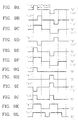
- Figures 9A through 9L are operational waveform diagrams of the data decoding apparatus shown in Figure 8, illustrating a process of decoding a reproduction signal input to the Viterbi decoder 780 in the case when no noise is overlapped with a channel.
- Figure 9A shows a waveform of a signal Vs output from the SAMPLE & HOLD 710
- Figure 9B shows a waveform of a signal produced by delaying the signal Vs output from the SAMPLE & HOLD 710 by the delay 722 of the first pre-filter 720
- Figure 9C shows a waveform of an output signal of the first pre-filter 720
- Figure 9D shows a waveform of a feed-back signal Fsl output from the delay 732 of the first reverse pre-filter 730.
- the feed-back signal Fsl is detected from the output signal of the peak detector 740.
- this signal is a signal converted into a digital level. Since the feed-back signal Fsl does not includes analog noise, the first reverse pre-filter 730 can perform a 1/(1+D) operation without increasing noise.
- Figure 9E shows a waveform of an output signal of the first reverse pre-filter 730
- Figure 9F shows a waveform of a signal produced by delaying the output of the first reverse pre-filter 730 by the delay 752 of the second pre-filter 750
- Figure 9G shows a waveform of a positive peak value Hn output from the second positive peak value detector 773
- Figure 9H shows a waveform of a negative peak value output from the second negative peak value detector 775.
- Figure 9I shows a waveform of a feed-back signal Fs2 output from the delay 762 of the second reverse pre-filter 760
- Figure 9J shows a waveform of decoded data output from the Viterbi decoder 780
- Figure 9K is a waveform of an output signal of the first channel demodulator 790
- Figure 9L shows a waveform of an output signal of the second channel demodulator 800.
- an embodiment having a PR4(+1, 0, -1) channel such as a digital magnetic recording/reproducing apparatus, when a reproduction signal is decoded by a Viterbi decoding method, is constructed such that the noise level corresponds to that of a PR4(+1, 0, -1) system and the aperture ratio of an eye pattern corresponds to that of a PR(+1, -1) system.
- a state detector and a Viterbi decoder are constructed into one channel, such that the efficiency of the Viterbi decoder is improved, compared to that of a PR4(+1, 0, -1) system, and state detection is allowed by a PR(+1, -1) system.
- remarkable competitiveness can be secured in view of easy implementation and manufacturing cost.
- a Viterbi decoder comprised of one channel is constructed, such that the efficiency of the Viterbi decoder is improved and state detection is allowed by the PR(+1, -1) system. In other words, remarkable competiveness can be secured in view of easy implementation and manufacturing cost.
- embodiments of the present invention have the effect of selectively decoding data in various types in addition to each type in a system having a PR4 channel or an E n PR4 channel.
Landscapes
- Engineering & Computer Science (AREA)
- Signal Processing (AREA)
- Physics & Mathematics (AREA)
- Probability & Statistics with Applications (AREA)
- Spectroscopy & Molecular Physics (AREA)
- Computer Networks & Wireless Communication (AREA)
- Algebra (AREA)
- Pure & Applied Mathematics (AREA)
- Theoretical Computer Science (AREA)
- Signal Processing For Digital Recording And Reproducing (AREA)
- Error Detection And Correction (AREA)
Claims (22)
- Datendekodiervorrichtung für ein einen PR4-Kanal aufweisendes System mit einem eine 1/(1+D)-Kennlinie aufweisenden Vorkodierer, wobei die Vorrichtung umfasst:
einen nach der Methode der größten Wahrscheinlichkeit arbeitenden Dekodierer (420, 430; 540, 550) mit einem Kanal zum nach der Methode der größten Wahrscheinlichkeit erfolgenden Dekodieren eines über den Kanal empfangenen PR(+1, -1)-Signals, sodass nach der Methode der größten Wahrscheinlichkeit dekodierte Daten ausgegeben werden; und
einen Kanaldemodulator (440; 560; 790, 800) mit einer die inverse Kennlinie des Vorkodierers darstellenden (1+D)-Kennlinie zum Kanaldemodulieren der nach der Methode der größten Wahrscheinlichkeit dekodierten Daten, sodass dekodierte Daten ausgegeben werden,
wobei der nach der Methode der größten Wahrscheinlichkeit arbeitende Dekodierer umfasst:
einen Zustandsdetektor (420; 540; 740, 770) zum Erfassen positiver und negativer Zustandswerte des PR(+1, -1)-Signals entsprechend positiven und negativen Schwellenwerten mit einer Schwankung entsprechend dem über den Kanal empfangenen PR(+1, -1)-Signal; und
einen Viterbi-Dekodierer (430; 550) zum Empfangen der positiven und negativen Zustandswerte und zum Viterbi-Dekodieren derselben. - Vorrichtung nach Anspruch 1, wobei die Vorrichtung des Weiteren umfasst:
einen eine (1+D)-Kennlinie aufweisenden Vorfilter (520) zum Umwandeln des über den Kanal empfangenen PR(+1, -1)-Signals in ein PR4(+1, 0, -1)-Signal; und
einen eine 1/(1+D)-Kennlinie aufweisenden inversen Vorfilter (530) zum Wiederumwandeln des über den Kanal empfangenen PR4(+1, 0, -1)-Signals in ein PR(+1, -1)-Signal;
wobei der nach der Methode der größten Wahrscheinlichkeit arbeitende Dekodierer (540, 550) der nach der Methode der größten Wahrscheinlichkeit erfolgenden Dekodierung des von dem inversen Vorfilter ausgegebenen PR(+1, -1)-Signals dient. - Vorrichtung nach Anspruch 2, wobei der Vorfilter (520) umfasst:
einen ersten Verzögerer (D) zum Verzögern des über den Kanal empfangenen PR(+1, -1)-Signals um einen Einheitswert, sodass das verzögerte Signal ausgegeben wird; und
einen ersten Addierer (521) zum Addieren des verzögerten Signals zu dem über den Kanal empfangenen PR(+1, -1)-Signal, sodass ein erstes PR4(+1, 0, -1)-Modus-Addiersignal ausgegeben wird. - Vorrichtung nach Anspruch 2 oder 3, wobei der inverse Vorfilter (530) umfasst:einen Subtrahierer (531) zum Subtrahieren des positiven Zustandswertes von dem negativen Zustandswert;einen zweiten Verzögerer (532) zum Verzögern der Ausgabe des Subtrahierers (531) um einen Einheitswert, sodass ein Rückkopplungssignal ausgegeben wird; undeinen zweiten Addierer (533) zum Addieren des ersten Addiersignals zu dem Rückkopplungssignal, sodass ein PR(+1, -1)-Signal ausgegeben wird.
- Vorrichtung nach einem der Ansprüche 2, 3 oder 4, wobei der Kanaldemodulator (560) umfasst:ein D-Flipflop (562) zum Einheitsverzögern der nach der Methode der größten Wahrscheinlichkeit dekodierten Daten um einen Einheitswert; undeine XOR-Logikschaltung (561) zum Ausführen einer XOR-Operation an den nach der Methode der größten Wahrscheinlichkeit dekodierten Daten und der Ausgabe des D-Flipflops (562).
- Vorrichtung nach einem der vorhergehenden Ansprüche, wobei die Vorrichtung des Weiteren umfasst:eine Abtast-Halte-Schaitung (410; 510) zum Abtasten und Halten des über den Kanal empfangenen PR(+1, -1)-Signals; undeinen Zeittaktdetektor (450; 570) zum Erfassen des Zeittaktes des über den Kanal empfangenen PR(+1, -1)-Signals, sodass der Betriebstakt der Abtast-Halte-Schaltung (410; 510), des nach der Methode der größten Wahrscheinlichkeit arbeitenden Dekodierers (420, 430; 540, 550) und des Kanaldemodulators (440; 560)erzeugt wird.
- Vorrichtung nach einem der vorhergehenden Ansprüche, wobei die Vorrichtung des Weiteren umfasst:
einen Analog-Digital-(A/D)-Wandler zum Umwandeln des über den Kanal empfangenen PR(+1, -1)-Signals in digitale Daten; und
einen Zeittaktdetektor (450; 570) zum Erfassen des Zeittaktes des über den Kanal empfangenen PR(+1, -1)-Signals, sodass der Betriebstakt der Abtast-Halte-Schaltung (410; 510), des nach der Methode der größten Wahrscheinlichkeit arbeitenden Dekodierers (420, 430; 540, 550) und des Kanaldemodulators (440; 560) erzeugt wird. - Vorrichtung nach Anspruch 1, wobei die Vorrichtung des Weiteren umfasst:
eine Einheit mit n+1 in Reihe angeordneten Untereinheiten, wobei jede Untereinheit einen Vorfilter (720; 750), einen Zustandsdetektor (740; 770) und einen inversen Vorfilter (730; 760) aufweist, und wobei jede Untereinheit umfasst: einen eine (1+D)-Kennlinie aufweisenden Vorfilter (720; 750) zum Umwandeln des über den Kanal empfangenen PR(+1, -1)-Signals in ein PR4(+1, 0, -1)-Signal und einen eine 1/(1+D)-Kennlinie aufweisenden inversen Vorfilter (730; 760) zum Rückkopplungsempfangen der positiven und negativen Zustandswerte, zum Wiederumwandeln des PR4(+1, 0, -1)-Signals in das PR(+1, -1)-Signal und zum Ausgeben des umgewandelten Signals an den Zustandsdetektor (740; 770);
wobei der Kanaldemodulator erste und zweite Kanaldemodulatoren aufweist,
wobei der eine (1+D)-Kennlinie und damit die inverse Kennlinie des Vorkodierers aufweisende erste Kanaldemodulator (790) dem Kanaldemodulieren der Viterbi-dekodierten Daten dient, sodass dekodierte PR4-Modus-Daten ausgegeben werden; und
wobei der eine (1+D)n-Kennlinie aufweisende Kanaldemodulator (800) dem Kanaldemodulieren der Ausgabe des ersten Kanaldemodulators (790) dient, sodass dekodierte EnPR4-Modus-Daten ausgegeben werden; und
eine Auswähleinheit (810) zum Auswählen einer der Ausgaben der ersten und zweiten Kanaldemodulatoren (790, 800) entsprechend einem PR4/EnPR4-Modus-Signal. - Vorrichtung nach Anspruch 8, wobei der erste Kanaldemodulator umfasst:einen Einheitsverzögerer (792) zum Verzögern der nach der Methode der größten Wahrscheinlichkeit dekodierten Daten um einen Einheitswert; undeine XOR-Logikschaltung (791) zum Ausführen einer XOR-Operation an den nach der Methode der größten Wahrscheinlichkeit dekodierten Daten und der Ausgabe des Einheitsverzögerers (792).
- Vorrichtung nach einem der Ansprüche 8 oder 9, wobei der zweite Kanaldemodulator (800) umfasst:n in Reihe angeordnete Verzögerer (802) zum n-Bit-Verzögern der Ausgabe des ersten Kanaldemodulators (790); undeine XOR-Logikschaltung (801) zum Ausführen einer XOR-Operation an den Ausgaben des ersten Kanaldemodulators (790) und den Ausgaben der n Verzögerer (802).
- Datendekodiervorrichtung für ein einen EnPR4-Kanal aufweisendes System mit einem eine 1/(1+D)n+1-Kennlinie aufweisenden Vorkodierer, wobei die Vorrichtung umfasst:
eine Einheit mit n+1 in Reihe angeordneten Untereinheiten, wobei jede Untereinheit einen Vorfilter (620; 650), einen Zustandsdetektor (640; 670) und einen inversen Vorfilter (630; 660) aufweist, und wobei jede Untereinheit umfasst: einen eine (1+D)-Kennlinie aufweisenden Vorfilter (620; 650) zum Umwandeln des über den Kanal empfangenen PR(+1, -1)-Signals in ein PR4(+1, 0, -1)-Signal, einen Zustandsdetektor (640; 670) zum Erfassen positiver und negativer Zustandswerte des PR(+1, -1)-Signals in Abhängigkeit von positiven und negativen Schwellenwerten mit einer Schwankung entsprechend dem PR(+1, -1)-Signal, und einen inversen Vorfilter (630; 660) zum Rückkopplungsempfangen der positiven und negativen Zustandswerte, zum Wiederumwandeln des PR4(+1, 0, -1)-Signals in das PR(+1, -1)-Signal und zum Ausgeben des umgewandelten Signals an den Zustandsdetektor (640; 670);
einen Viterbi-Dekodierer (680) mit einem Kanal zum Viterbi-Dekodieren des von der Einheit ausgegebenen PR(+1, -1)-Signals und zum Ausgeben der Viterbi-dekodierten Daten; und
einen eine (1+D)n+1-Kennlinie und damit die inverse Kennlinie des Vorkodierers aufweisenden Kanaldemodulator (690) zum Kanaldemodulieren der Viterbi-dekodierten Daten, sodass dekodierte Daten ausgegeben werden. - Vorrichtung nach Anspruch 11, wobei der Kanaldemodulator (690) umfasst:
n+1 in Reihe angeordnete Verzögerer (682, 693) zum (n+1)-Bit-Verzögem der nach der Methode der größten Wahrscheinlichkeit dekodierten Daten; und
eine XOR-Logikschaltung (691) zum Ausführen einer XOR-Operation an den nach der Methode der größten Wahrscheinlichkeit dekodierten Daten aus dem Viterbi-Dekodierer (86) und den Ausgaben der n+1 Verzögerer (682; 693). - Vorrichtung nach Anspruch 8 oder 11, wobei der erste Vorfilter (620; 720) der Einheit umfasst:
einen ersten Verzögerer (622; 722) zum Verzögern des über den Kanal empfangenen PR(+1, -1)-Signals um einen Einheitswert, sodass ein erstes verzögertes Signal ausgegeben wird; und
einen Addierer (621; 721) zum Addieren des über den Kanal empfangenen PR(+1, -1)-Signals zu dem verzögerten Signal, sodass ein erstes PR4(+1, 0, -1)-Modus-Addiersignal ausgegeben wird, und wobei jeder von dem zweiten bis (n+1)-ten Vorfilter (650; 750) umfasst:
einen Verzögerer (652; 752) zum Verzögern des von dem direkt vorhergehenden inversen Vorfilter (630; 730) ausgegebenen PR(+1, -1)-Signals um eine Einheitsperiode, sodass ein verzögertes Signal ausgegeben wird; und
einen Addierer (651; 751) zum Addieren des von dem direkt vorhergehenden inversen Vorfilter (630; 730) ausgegebenen PR(+1, -1)-Signals zu dem verzögerten Signal, sodass ein PR4(+1, 0, -1)-Signal ausgegeben wird. - Vorrichtung nach einem der Ansprüche 8, 11 oder 13, wobei jeder der inversen Vorfilter (630, 660; 730, 760) umfasst:ein Subtrahierer (631, 661; 731, 761) zum Subtrahieren des positiven Zustandswertes von dem negativen Zustandwert von der Ausgabe des Zustandsdetektors (640, 670; 740, 770);einen zweiten Verzögerer (632, 662; 732, 762) zum Verzögern der Ausgabe des zweiten Subtrahierers (731, 761) um einen Einheitswert, sodass ein Rückkopplungssignal ausgegeben wird; undeinen zweiten Addierer (623, 663; 733, 763) zum Addieren des Ausgabesignals des Vorkodierers (620, 650; 720, 750) zu dem Rückkopplungssignal.
- Vorrichtung nach einem der Ansprüche 8, 11, 13 oder 14, wobei die Vorrichtung des Weiteren umfasst:
eine Abtast-Halte-Schaltung (610; 710) zum Abtasten und Halten eines über den Kanal empfangenen PR(+1, -1)-Signals; und
einen Zeittaktdetektor (700; 800) zum Erfassen des Zeittaktes des über den Kanal empfangenen PR(+1, -1)-Signals, sodass ein Betriebstakt der Abtast-Halte-Schaltung (610; 710), des Viterbi-Dekodierers (680; 780) und des Kanaldemodulators (690; 790, 800) erzeugt wird. - Vorrichtung nach einem der Ansprüche 8, 11, 13, 14 oder 15, des Weiteren umfassend:
einen Analog-Digital-(A/D)-Wandler zum Umwandeln des über den Kanal empfangenen PR(+1, -1)-Signals in digitale Daten; und
einen Zeittaktdetektor (700; 800) zum Erfassen des Zeittaktes des über den Kanal empfangenen PR(+1, -1)-Signals, sodass der Betriebstakt der Abtast-Halte-Schaltung (610; 710), des Viterbi-Dekodierers (680; 780) und des Kanaldemodulators (690; 790, 800) erzeugt wird. - Vorrichtung nach Anspruch 11, wobei
m Untereinheiten mit einer größer als n+1 seienden ganzen Zahl m in Reihe angeordnet sind; und
wobei die Vorrichtung des Weiteren umfasst:
einen eine (1+D)p-Kennlinie mit p = m-n-1 aufweisenden zweiten Kanaldemodulator (800) zum Kanaldemodulieren der Ausgabe des ersten Kanaldemodulators, sodass zweite dekodierte Daten ausgegeben werden; und
eine Auswähleinheit (810) zum Auswählen einer der Ausgaben der ersten und zweiten Kanaldemodulatoren entsprechend einem Modus-Signal. - Datendekodierverfahren zur Verwendung in einer einen PR4-Kanal aufweisenden Vorrichtung mit einem eine 1/(1+D)-Kennlinie aufweisenden Vorkodierer, wobei das Datendekodierverfahren die nachfolgenden Schritte umfasst:wobei der Schritt (a) die nachfolgenden Schritte umfasst:(a) ein nach der Methode der größten Wahrscheinlichkeit erfolgendes direktes Dekodieren eines über den Kanal empfangenen PR(+1, -1)-Signals, sodass nach der Methode der größten Wahrscheinlichkeit dekodierte Daten ausgegeben werden; und(b) ein Einheitsbit-Verzögem der nach der Methode der größten Wahrscheinlichkeit dekodierten Daten mit dem Ziel einer die inverse Kennlinie des Vorkodierers darstellenden (1+D)-Kennlinie, ein Addieren der verzögerten Daten zu den nach der Methode der größten Wahrscheinlichkeit dekodierten Daten, sodass dekodierte Daten ausgegeben werden,(a1) ein Erfassen positiver und negativer Zustandswerte des PR(+1, -1)-Signals in Abhängigkeit von positiven und negativen Schwellenwerten mit einer Schwankung entsprechend dem über den Kanal empfangenen PR(+1, -1)-Signal; und(a2) ein Empfangen der positiven und negativen Zustandswerte und Viterbi-Dekodieren derselben.
- Datendekodierverfahren zur Verwendung in einer einen PR4-Kanal aufweisenden Vorrichtung mit einem eine 1/(1+D)-Kenntinie aufweisenden Vorkodierer, wobei das Datendekodierverfahren die nachfolgenden Schritte umfasst:(a) ein Einheitsbit-Verzögern eines über den Kanal empfangenen PR(+1, -1)-Signals mit dem Ziel einer (1+D)-Kennlinie, ein Addieren des verzögerten Signals zu dem PR(+1, -1)-Signal, um das Ergebnis wieder in das PR4(+1, 0, -1)-Signal umzuwandeln;(b) ein Addieren des PR4(+1, 0, -1)-Signals zu einem Rückkopplungssignal mit dem Ziel einer (1+D)-Kennlinie, um das Ergebnis wieder in das PR(+1, -1)-Signal umzuwandeln;(c) ein Erfassen positiver und negativer Zustandswerte des PR(+1, -1)-Signals in Abhängigkeit von positiven und negativen Schwellenwerten mit einer Schwankung entsprechend dem in dem Schritt (b) umgewandelten PR(+1, -1)-Signal, und ein Ausgeben des durch Subtrahieren des positiven Zustandswertes von dem negativen Zustandswert entstandenen Rückkopplungssignals;(d) ein Empfangen der positiven und negativen Zustandswerte und ein Viterbi-Dekodieren derselben, sodass Viterbi-dekodierte Daten entstehen; und(e) ein Verzögern der Viterbi-dekodierten Daten mit dem Ziel einer die inverse Kennlinie des Vorkodierers darstellenden (1+D)-Kennlinie, und ein Addieren der verzögerten Daten zu den Viterbi-dekodierten Daten, sodass dekodierte Daten ausgegeben werden.
- Verfahren nach Anspruch 19, wobei die Schritte (a) bis (c) (n+1)-mal wiederholt werden; und
wobei der Schritt (b) umfasst: ein Viterbi-Dekodieren des nach der (n+1)-maligen Wiederholung der Schritte (a) bis (c) ausgegebenen PR(+1, -1)-Signals und ein Ausgeben der Viterbi-dekodierten Daten; und
wobei der Schritt (e) umfasst: ein Einheitsbit-Verzögem des Viterbi-dekodierten Signals mit dem Ziel einer die inverse Kennlinie des Vorkodierers darstellenden (1+D)-Kennlinie, und ein Addieren der verzögerten Daten zu den Viterbi-dekodierten Daten, sodass PR4-Modus-dekodierte Daten ausgegeben werden;
wobei das Verfahren darüber hinaus die nachfolgenden Schritte umfasst:(f) ein n-Bit-Verzögern des PR4-Modus-dekodierten Signals mit dem Ziel einer (1+D)n-Kennlinie, und ein Addieren der n-Bit-verzögerten Daten zu den PR4-Modus-dekodierten Daten, sodass EnPR4-Modus-dekodierte Daten ausgegeben werden; und(g) ein Auswählen einer der PR4-Modus-dekodierten Daten und der E"PR4-Modus-dekodierten Daten entsprechend einem PR4/EnPR4-Modus-Signal. - Datendekodierfahren zur Verwendung in einer einen EnPR4-Kanal aufweisenden Vorrichtung mit einem eine 1/(1+D)n+1-Kennlinie aufweisenden Vorkodierer, wobei das Datendekodierverfahren die nachfolgenden Schritte umfasst:(a) ein Einheitsbit-Verzögern eines über den Kanal empfangenen PR(+1, -1)-Signals mit dem Ziel einer (1+D)-Kennlinie, ein Addieren des verzögerten Signals zu dem PR(+1, -1)-Signal, um das Ergebnis in ein PR4(+1, 0, -1)-Signal umzuwandeln;(b) ein Addieren des PR4(+1, 0, -1)-Signals zu einem Rückkopplungssignal mit dem Ziel einer (1+D)-Kennlinie, um das Ergebnis wieder in das PR(+1, -1)-Signal umzuwandeln;(c) ein Erfassen positiver und negativer Zustandswerte des PR(+1, -1)-Signals in Abhängigkeit von positiven und negativen Schwellenwerten mit einer Schwankung entsprechend dem in dem Schritt (b) umgewandelten PR(+1, -1)-Signal, und ein Ausgeben des durch Subtrahieren des positiven Zustandswertes von dem negativen Zustandswert erhaltenen Rückkopplungssignals;(d) ein (n+1)-maliges Wiederholen der Schritte (a) bis (c);(e) ein Viterbi-Dekodieren des nach Ausführen des Schrittes (d) ausgegebenen PR(+1, -1)-Signals und ein Ausgeben der Viterbi-dekodierten Daten; und(f) ein Addieren der (n+1)-Bit-verzögerten Daten der Viterbi-dekodierten Daten zu den Viterbi-dekodierten Daten mit dem Ziel einer die inverse Kennlinie des Vorkodierers darstellenden (1+D)n+1-Kennlinie und ein Ausgeben dekodierter Daten.
- Verfahren nach Anspruch 21, wobei die Schritte (a) bis (c) bei dem Schritt (d) m-mal mit einer größer als n+1 seienden ganzen Zahl m wiederholt werden, wobei der Schritt (f) umfasst:
ein (n+1)-Bit-Verzögern der Viterbi-dekodierten Daten mit dem Ziel einer die inverse Kennlinie des Vorkodierers darstellenden (1+D)n+1-Kennlinie und ein Addieren der (n+1 )-Bit-verzögerten Daten zu den Viterbi-dekodierten Daten, sodass erste EnPR4-Modus-dekodierte Daten ausgegeben werden;
wobei das Verfahren des Weiteren die nachfolgenden Schritte umfasst:(g) ein p-Bit-Verzögern der ersten dekodierten Daten mit dem Ziel einer (1+D)p-Kennlinie mit p = m-n-1, ein Addieren der p-Bit-verzögerten Daten zu den ersten verzögerten Daten, sodass zweite dekodierte Daten ausgegeben werden; und(h) ein Auswählen von einem der ersten dekodierten Daten und der zweiten dekodierten Daten entsprechend einem Modus-Signal.
Applications Claiming Priority (2)
| Application Number | Priority Date | Filing Date | Title |
|---|---|---|---|
| KR1019970031992A KR100243218B1 (ko) | 1997-07-10 | 1997-07-10 | 데이터 복호장치와 그 방법 |
| KR9731992 | 1997-07-10 |
Publications (3)
| Publication Number | Publication Date |
|---|---|
| EP0891059A2 EP0891059A2 (de) | 1999-01-13 |
| EP0891059A3 EP0891059A3 (de) | 2001-09-12 |
| EP0891059B1 true EP0891059B1 (de) | 2004-04-07 |
Family
ID=19514019
Family Applications (1)
| Application Number | Title | Priority Date | Filing Date |
|---|---|---|---|
| EP98301315A Expired - Lifetime EP0891059B1 (de) | 1997-07-10 | 1998-02-23 | Folgeschätzung für Teilantwortkanäle |
Country Status (6)
| Country | Link |
|---|---|
| US (1) | US6188735B1 (de) |
| EP (1) | EP0891059B1 (de) |
| JP (1) | JP2950375B2 (de) |
| KR (1) | KR100243218B1 (de) |
| CN (1) | CN1140055C (de) |
| DE (1) | DE69822929T2 (de) |
Families Citing this family (11)
| Publication number | Priority date | Publication date | Assignee | Title |
|---|---|---|---|---|
| US6563889B1 (en) * | 1998-10-01 | 2003-05-13 | Lsi Logic Corporation | Method and apparatus for adapting the boost of a read channel filter |
| JP2000149436A (ja) * | 1998-11-02 | 2000-05-30 | Sony Corp | ディジタル情報再生装置および再生方法 |
| US6522705B1 (en) * | 1999-03-01 | 2003-02-18 | Stmicroelectronics N.V. | Processor for digital data |
| US6680980B1 (en) * | 1999-09-03 | 2004-01-20 | Infineon Technologies North America Corp. | Supporting ME2PRML and M2EPRML with the same trellis structure |
| JP4161487B2 (ja) * | 1999-11-01 | 2008-10-08 | ソニー株式会社 | データ復号装置及び方法 |
| US6584143B2 (en) * | 2001-03-02 | 2003-06-24 | Motorola, Inc. | Method and apparatus for joint detection of a coded signal in a CDMA system |
| US6587501B2 (en) * | 2001-07-30 | 2003-07-01 | Motorola, Inc. | Method and apparatus for joint detection of a coded signal in a CDMA system |
| KR100787214B1 (ko) * | 2005-08-25 | 2007-12-21 | 삼성전자주식회사 | 아날로그 비터비 디코더 |
| JP5374156B2 (ja) * | 2005-11-07 | 2013-12-25 | エージェンシー フォー サイエンス, テクノロジー アンド リサーチ | データを復号化及び符号化するための装置及び方法 |
| US8493247B2 (en) * | 2011-12-20 | 2013-07-23 | General Electric Company | Methods and systems for decoding data |
| CN115499024B (zh) * | 2022-09-15 | 2024-03-15 | 香港科技大学 | 一种pam4信号接收机及其自适应均衡控制方法 |
Family Cites Families (12)
| Publication number | Priority date | Publication date | Assignee | Title |
|---|---|---|---|---|
| JPH04355268A (ja) | 1991-06-01 | 1992-12-09 | Fujitsu Ltd | 磁気記録再生装置の記録再生方法 |
| JP3259302B2 (ja) * | 1992-01-28 | 2002-02-25 | 株式会社日立製作所 | 出力信号復号方法および装置 |
| JPH06243580A (ja) * | 1993-02-15 | 1994-09-02 | Hitachi Ltd | Agc回路 |
| US5521767A (en) * | 1993-09-17 | 1996-05-28 | Quantum Corporation | Optimized equalizer system for data recovery and timing extraction in partial response read channels |
| US5661760A (en) * | 1995-10-23 | 1997-08-26 | Quantum Corporation | Wide biphase digital servo information detection, and estimation for disk drive using servo Viterbi detector |
| US5585975A (en) * | 1994-11-17 | 1996-12-17 | Cirrus Logic, Inc. | Equalization for sample value estimation and sequence detection in a sampled amplitude read channel |
| JPH08147887A (ja) * | 1994-11-18 | 1996-06-07 | Hitachi Ltd | 復号回路および再生装置 |
| US5638065A (en) * | 1995-06-13 | 1997-06-10 | International Business Machines Corporation | Maximum-likelihood symbol detection for RLL-coded data |
| JPH09167456A (ja) * | 1995-12-15 | 1997-06-24 | Fujitsu Ltd | ディスク装置及びディスク媒体 |
| US5861825A (en) * | 1996-03-21 | 1999-01-19 | Sony Corporation | Method and device for code modulation, method and device for code demodulation, and method and device for decoding |
| US5949357A (en) * | 1997-01-13 | 1999-09-07 | Quantum Corporation | Time-varying maximum-transition-run codes for data channels |
| US6035435A (en) * | 1997-09-30 | 2000-03-07 | Datapath Systems, Inc. | Method and apparatus for encoding a binary signal |
-
1997
- 1997-07-10 KR KR1019970031992A patent/KR100243218B1/ko not_active Expired - Fee Related
-
1998
- 1998-02-23 EP EP98301315A patent/EP0891059B1/de not_active Expired - Lifetime
- 1998-02-23 DE DE69822929T patent/DE69822929T2/de not_active Expired - Fee Related
- 1998-02-26 CN CNB981052606A patent/CN1140055C/zh not_active Expired - Fee Related
- 1998-02-27 US US09/032,115 patent/US6188735B1/en not_active Expired - Fee Related
- 1998-03-19 JP JP10070613A patent/JP2950375B2/ja not_active Expired - Fee Related
Also Published As
| Publication number | Publication date |
|---|---|
| JP2950375B2 (ja) | 1999-09-20 |
| CN1205578A (zh) | 1999-01-20 |
| DE69822929T2 (de) | 2004-09-02 |
| EP0891059A2 (de) | 1999-01-13 |
| KR19990009556A (ko) | 1999-02-05 |
| JPH1139805A (ja) | 1999-02-12 |
| DE69822929D1 (de) | 2004-05-13 |
| EP0891059A3 (de) | 2001-09-12 |
| US6188735B1 (en) | 2001-02-13 |
| KR100243218B1 (ko) | 2000-02-01 |
| CN1140055C (zh) | 2004-02-25 |
Similar Documents
| Publication | Publication Date | Title |
|---|---|---|
| US5459679A (en) | Real-time DC offset control and associated method | |
| US5734680A (en) | Analog implementation of a partial response maximum likelihood (PRML) read channel | |
| EP0981880B1 (de) | Anordnung und verfahren zur rauschvorhersagenden maximal-wahrscheinlichkeitsdetektion | |
| EP0746848A1 (de) | Synchroner lesekanal | |
| US5166955A (en) | Signal detection apparatus for detecting digital information from a PCM signal | |
| EP0891059B1 (de) | Folgeschätzung für Teilantwortkanäle | |
| US5774286A (en) | Magnetic disk drive in which read data is demodulated using maximum likelihood detection method | |
| JP3648308B2 (ja) | 等化器および磁気記録信号再生装置 | |
| US6067198A (en) | Apparatus and method for processing a data signal from a magnetic-media reading head | |
| JP2853671B2 (ja) | 情報検出装置 | |
| JP4251137B2 (ja) | 信号処理装置及び方法、並びにデジタルデータ再生装置 | |
| US20060093075A1 (en) | Whitening of data-dependent, non-stationary noise in an inter-symbol interference channel detector | |
| US5805478A (en) | Data detection method and apparatus in data storage device | |
| US6922384B2 (en) | Information reproducing apparatus | |
| JP2004326952A (ja) | 情報記憶再生装置 | |
| JP2642902B2 (ja) | サーボ信号処理デバイス | |
| EP0853805A2 (de) | Übertragung, aufzeichnung und wiedergabe eines digitalen informationssignals | |
| JP3591902B2 (ja) | 磁気記録再生装置の復調回路 | |
| US6879629B2 (en) | Method and apparatus for enhanced timing loop for a PRML data channel | |
| US7010065B2 (en) | Method and apparatus for word synchronization with large coding distance and fault tolerance for PRML systems | |
| JP2977031B2 (ja) | データ検出器及びその方法 | |
| JP3917317B2 (ja) | 等化・位相制御システム,およびそれを備えるディスク記憶装置 | |
| JPH07296524A (ja) | デイジタルデータ再生装置 | |
| US20060133255A1 (en) | Read channel apparatus for an optical storage system | |
| JP2001209902A (ja) | 再生装置、再生方法及び信号処理装置 |
Legal Events
| Date | Code | Title | Description |
|---|---|---|---|
| PUAI | Public reference made under article 153(3) epc to a published international application that has entered the european phase |
Free format text: ORIGINAL CODE: 0009012 |
|
| 17P | Request for examination filed |
Effective date: 19980305 |
|
| AK | Designated contracting states |
Kind code of ref document: A2 Designated state(s): AT BE CH DE DK ES FI FR GB GR IE IT LI LU MC NL PT SE Kind code of ref document: A2 Designated state(s): DE GB NL |
|
| AX | Request for extension of the european patent |
Free format text: AL;LT;LV;MK;RO;SI |
|
| PUAL | Search report despatched |
Free format text: ORIGINAL CODE: 0009013 |
|
| AK | Designated contracting states |
Kind code of ref document: A3 Designated state(s): AT BE CH DE DK ES FI FR GB GR IE IT LI LU MC NL PT SE |
|
| AX | Request for extension of the european patent |
Free format text: AL;LT;LV;MK;RO;SI |
|
| RIC1 | Information provided on ipc code assigned before grant |
Free format text: 7H 04L 25/03 A, 7H 04L 25/497 B, 7G 11B 20/10 B, 7G 11B 20/14 B, 7G 11B 5/09 B |
|
| 17Q | First examination report despatched |
Effective date: 20020107 |
|
| AKX | Designation fees paid |
Free format text: DE GB NL |
|
| GRAP | Despatch of communication of intention to grant a patent |
Free format text: ORIGINAL CODE: EPIDOSNIGR1 |
|
| GRAS | Grant fee paid |
Free format text: ORIGINAL CODE: EPIDOSNIGR3 |
|
| GRAA | (expected) grant |
Free format text: ORIGINAL CODE: 0009210 |
|
| AK | Designated contracting states |
Kind code of ref document: B1 Designated state(s): DE GB NL |
|
| REG | Reference to a national code |
Ref country code: GB Ref legal event code: FG4D |
|
| REF | Corresponds to: |
Ref document number: 69822929 Country of ref document: DE Date of ref document: 20040513 Kind code of ref document: P |
|
| PLBE | No opposition filed within time limit |
Free format text: ORIGINAL CODE: 0009261 |
|
| STAA | Information on the status of an ep patent application or granted ep patent |
Free format text: STATUS: NO OPPOSITION FILED WITHIN TIME LIMIT |
|
| 26N | No opposition filed |
Effective date: 20050110 |
|
| PGFP | Annual fee paid to national office [announced via postgrant information from national office to epo] |
Ref country code: NL Payment date: 20090203 Year of fee payment: 12 Ref country code: DE Payment date: 20090123 Year of fee payment: 12 |
|
| PGFP | Annual fee paid to national office [announced via postgrant information from national office to epo] |
Ref country code: GB Payment date: 20090217 Year of fee payment: 12 |
|
| REG | Reference to a national code |
Ref country code: NL Ref legal event code: V1 Effective date: 20100901 |
|
| GBPC | Gb: european patent ceased through non-payment of renewal fee |
Effective date: 20100223 |
|
| PG25 | Lapsed in a contracting state [announced via postgrant information from national office to epo] |
Ref country code: NL Free format text: LAPSE BECAUSE OF NON-PAYMENT OF DUE FEES Effective date: 20100901 |
|
| PG25 | Lapsed in a contracting state [announced via postgrant information from national office to epo] |
Ref country code: DE Free format text: LAPSE BECAUSE OF NON-PAYMENT OF DUE FEES Effective date: 20100901 |
|
| PG25 | Lapsed in a contracting state [announced via postgrant information from national office to epo] |
Ref country code: GB Free format text: LAPSE BECAUSE OF NON-PAYMENT OF DUE FEES Effective date: 20100223 |