EP0881023A2 - Schneid- und Schleifwerkzeug - Google Patents
Schneid- und Schleifwerkzeug Download PDFInfo
- Publication number
- EP0881023A2 EP0881023A2 EP98810492A EP98810492A EP0881023A2 EP 0881023 A2 EP0881023 A2 EP 0881023A2 EP 98810492 A EP98810492 A EP 98810492A EP 98810492 A EP98810492 A EP 98810492A EP 0881023 A2 EP0881023 A2 EP 0881023A2
- Authority
- EP
- European Patent Office
- Prior art keywords
- cutting
- tool
- cutting edge
- grinding tool
- tool according
- Prior art date
- Legal status (The legal status is an assumption and is not a legal conclusion. Google has not performed a legal analysis and makes no representation as to the accuracy of the status listed.)
- Granted
Links
Images

Classifications
-
- B—PERFORMING OPERATIONS; TRANSPORTING
- B23—MACHINE TOOLS; METAL-WORKING NOT OTHERWISE PROVIDED FOR
- B23D—PLANING; SLOTTING; SHEARING; BROACHING; SAWING; FILING; SCRAPING; LIKE OPERATIONS FOR WORKING METAL BY REMOVING MATERIAL, NOT OTHERWISE PROVIDED FOR
- B23D61/00—Tools for sawing machines or sawing devices; Clamping devices for these tools
- B23D61/12—Straight saw blades; Strap saw blades
- B23D61/123—Details of saw blade body
-
- A—HUMAN NECESSITIES
- A61—MEDICAL OR VETERINARY SCIENCE; HYGIENE
- A61B—DIAGNOSIS; SURGERY; IDENTIFICATION
- A61B17/00—Surgical instruments, devices or methods, e.g. tourniquets
- A61B17/14—Surgical saws ; Accessories therefor
- A61B17/142—Surgical saws ; Accessories therefor with reciprocating saw blades, e.g. with cutting edges at the distal end of the saw blades
-
- B—PERFORMING OPERATIONS; TRANSPORTING
- B23—MACHINE TOOLS; METAL-WORKING NOT OTHERWISE PROVIDED FOR
- B23D—PLANING; SLOTTING; SHEARING; BROACHING; SAWING; FILING; SCRAPING; LIKE OPERATIONS FOR WORKING METAL BY REMOVING MATERIAL, NOT OTHERWISE PROVIDED FOR
- B23D49/00—Machines or devices for sawing with straight reciprocating saw blades, e.g. hacksaws
- B23D49/10—Hand-held or hand-operated sawing devices with straight saw blades
- B23D49/11—Hand-held or hand-operated sawing devices with straight saw blades for special purposes, e.g. offset-blade hand; Hand saws having spaced blades; Hand saws for sawing grooves or square holes
-
- B—PERFORMING OPERATIONS; TRANSPORTING
- B23—MACHINE TOOLS; METAL-WORKING NOT OTHERWISE PROVIDED FOR
- B23D—PLANING; SLOTTING; SHEARING; BROACHING; SAWING; FILING; SCRAPING; LIKE OPERATIONS FOR WORKING METAL BY REMOVING MATERIAL, NOT OTHERWISE PROVIDED FOR
- B23D51/00—Sawing machines or sawing devices working with straight blades, characterised only by constructional features of particular parts; Carrying or attaching means for tools, covered by this subclass, which are connected to a carrier at both ends
- B23D51/08—Sawing machines or sawing devices working with straight blades, characterised only by constructional features of particular parts; Carrying or attaching means for tools, covered by this subclass, which are connected to a carrier at both ends of devices for mounting straight saw blades or other tools
- B23D51/10—Sawing machines or sawing devices working with straight blades, characterised only by constructional features of particular parts; Carrying or attaching means for tools, covered by this subclass, which are connected to a carrier at both ends of devices for mounting straight saw blades or other tools for hand-held or hand-operated devices
-
- B—PERFORMING OPERATIONS; TRANSPORTING
- B23—MACHINE TOOLS; METAL-WORKING NOT OTHERWISE PROVIDED FOR
- B23D—PLANING; SLOTTING; SHEARING; BROACHING; SAWING; FILING; SCRAPING; LIKE OPERATIONS FOR WORKING METAL BY REMOVING MATERIAL, NOT OTHERWISE PROVIDED FOR
- B23D61/00—Tools for sawing machines or sawing devices; Clamping devices for these tools
- B23D61/006—Oscillating saw blades
-
- B—PERFORMING OPERATIONS; TRANSPORTING
- B23—MACHINE TOOLS; METAL-WORKING NOT OTHERWISE PROVIDED FOR
- B23D—PLANING; SLOTTING; SHEARING; BROACHING; SAWING; FILING; SCRAPING; LIKE OPERATIONS FOR WORKING METAL BY REMOVING MATERIAL, NOT OTHERWISE PROVIDED FOR
- B23D61/00—Tools for sawing machines or sawing devices; Clamping devices for these tools
- B23D61/12—Straight saw blades; Strap saw blades
-
- B—PERFORMING OPERATIONS; TRANSPORTING
- B24—GRINDING; POLISHING
- B24B—MACHINES, DEVICES, OR PROCESSES FOR GRINDING OR POLISHING; DRESSING OR CONDITIONING OF ABRADING SURFACES; FEEDING OF GRINDING, POLISHING, OR LAPPING AGENTS
- B24B23/00—Portable grinding machines, e.g. hand-guided; Accessories therefor
- B24B23/04—Portable grinding machines, e.g. hand-guided; Accessories therefor with oscillating grinding tools; Accessories therefor
-
- B—PERFORMING OPERATIONS; TRANSPORTING
- B27—WORKING OR PRESERVING WOOD OR SIMILAR MATERIAL; NAILING OR STAPLING MACHINES IN GENERAL
- B27B—SAWS FOR WOOD OR SIMILAR MATERIAL; COMPONENTS OR ACCESSORIES THEREFOR
- B27B19/00—Other reciprocating saws with power drive; Fret-saws
- B27B19/006—Other reciprocating saws with power drive; Fret-saws with oscillating saw blades; Hand saws with oscillating saw blades
-
- B—PERFORMING OPERATIONS; TRANSPORTING
- B28—WORKING CEMENT, CLAY, OR STONE
- B28D—WORKING STONE OR STONE-LIKE MATERIALS
- B28D1/00—Working stone or stone-like materials, e.g. brick, concrete or glass, not provided for elsewhere; Machines, devices, tools therefor
- B28D1/02—Working stone or stone-like materials, e.g. brick, concrete or glass, not provided for elsewhere; Machines, devices, tools therefor by sawing
- B28D1/12—Saw-blades or saw-discs specially adapted for working stone
- B28D1/127—Straight, i.e. flat, saw blades; strap saw blades
-
- A—HUMAN NECESSITIES
- A61—MEDICAL OR VETERINARY SCIENCE; HYGIENE
- A61B—DIAGNOSIS; SURGERY; IDENTIFICATION
- A61B17/00—Surgical instruments, devices or methods, e.g. tourniquets
- A61B17/14—Surgical saws ; Accessories therefor
Definitions
- the invention relates to a cutting and Grinding tool engages with a tool to get certain cutting edge according to the preamble of Claim 1.
- Cutting systems are known from the prior art which comprise cutting tools which are placed on the output shaft of a machine tool, the output shaft executing an oscillating rotary movement.
- the rotary movement usually comprises approximately 2 degrees of angle and a frequency of approximately 20,000 / min.
- These tools can be used for many purposes, or they are designed accordingly.
- Most of these known tools are used, for example, to remove hard-bonded windows on automobiles from the body without damage, to saw through, grind or cut body parts, to remove joints on tiles, etc.
- the cutting edges of these tools are spoon-like or sickle-like educated; in any case, the cutting parts which come into engagement with the workpiece run in an arcuate manner, the arc coinciding with the arcuate movement carried out by the tool or can be inclined to it.
- the object of the invention is to create a tool with the incisions and punctures in a workpiece possible are where the side incision or Ground edges perpendicular to the surface of the workpiece lie and run straight.
- the straight line arrangement of the cutting elements on the Cutting edge and the tangential course of the cutting edge with regard to the pivot point of the oscillation enables one lying parallel to the surface of the workpiece Cut course and thereby the generation of rectangular Recesses and cuts also in corners of Workpieces.
- the cutting tool can be Training of cutting elements for work in wood, plaster, use in composite materials, stone and metal.
- the saw teeth lie on two or more straight lines at an angle to one another.
- a base surface running essentially at right angles to the puncture or a cut surface driven parallel to the surface at the tap hole can be produced.
- the lateral taper of the cutting tool and / or a central longitudinal cut within the cutting tool allow optimal chip removal and prevent the cutting tool from jamming between the cutting surfaces generated by the cutting tool.
- the saw tool has a taper on both sides directly behind the saw teeth, or a longitudinal section is formed in the central part of the saw tool, which can pick up the chips and remove them to the rear.
- the tool feed requires a low feed force because the tool is automatically in the workpiece can incorporate.
- cuts can be aligned to one existing surface into an angled surface produce.
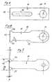
- Hand-held machine tool 1 has a handle part 3 with the drive motor and an angular gear part 5 with an invisible angular gear arranged therein on which an output shaft 7 carries at the end a fastener 9, e.g. a Screw, with which a tool 11 is rotatably connected to the output shaft 7.
- a fastener 9 e.g. a Screw
- the Output shaft 7 performs an oscillating rotary movement around the axis A in a range of approx. 2 angular degrees and with a preferably infinitely variable frequency from 0 to 20,000 and more strokes per minute.
- the cutting tool 11 comprises a cutting edge 13, which each with a serration, preferably with Cross cut or set cut, with Industrial diamonds or for working in metal with corundum or other abrasive substances.
- the In the exemplary embodiment, cutting tool 11 comprises an essentially trapezoidal plate 15 at the base of which Cutting edge 13 is formed.
- the plate preferably has 15 a level 17, the height h of at least the thickness d of the fastener 9 corresponds.
- the length L of the Cutting tool, measured from the pivot point of axis A to for cutting edge 13 can vary depending on the application. To the Of course, creating deep cuts must be one greater length L are provided than for the attachment of not very deep grooves, for example.
- length L causes the angle of rotation to remain the same the machine tool 1 has a larger stroke H / 2.
- a optimal length L is about 80 mm.
- the width B of the In the example, the cutting edge is approx. 60 mm. she can of course for generating very small Punctures can be much smaller and also depends on the Length L.
- the tooth tips of the teeth on the cutting edge 13 not on a straight line, but the Cutting edge 13 is in two at an angle to each other Split sections 21.
- the angle between the turn straight tooth tips in sections 21 is dull.
- the angles beta of the two sections 21 too an embodiment as described in Figures 2 to 6 are, for example, 1.5 ° to 2 °.
- the angle beta is preferably over two degrees; with shorter blades under two Degrees.
- a blade length of 100 mm i.e. a distance of the cutting edge 13 from the pivot point A of 100 mm an angle of 4.6 ° is preferably used.
- the formation of the cutting edge 13 depends, as already above mentioned on the type of material to be cut is, from.
- a cutting edge 13 has proven to be very advantageous proven with a cross cut or set cut for working in wood, plaster, e.g. when creating rectangular recesses on the building (in beams), e.g. Mortise and tenon holes, such as those used when joining beams are used to create shadow gaps, to Removing windows to be replaced to create of slots for inserting a plate, etc.
- Working with plastic composites or working in stone, industrial diamonds are preferred in conventionally applied to the cutting edge 13.
- metal can be used, for example, as corundum Cutting material can be used.
- the connection of the Cutting material (corundum, diamonds etc.) with the plate 15 takes place in a known manner as in the assembly of other tools with the appropriate ones Cutting materials.
- the handling of the cutting tool according to the invention is very easy. For example, in a room on one existing floor a parquet flooring or another covering should be relocated and this should be under the door frames reach to the existing floor, be guided, so can be easily a few millimeters incision above the existing floor and, if the door frame protrudes into the existing floor, too create an incision flush with the floor so that a clean slot for inserting the new floor is created.
- the puncture that deals with the inventive The cutting tool can not only run flush an area that is parallel to the cutting edge, but the puncture can also in corners of furniture or Rooms are made parallel to the side wall. There are therefore no reworking with chisels or the like necessary.
- the cutting tool in particular if it is a cross cut or set cut, works in essentially independent, i.e. with the least pressure, in the material to be cut into it.
- the straight forward running edge also causes the reason of the generated slot or hole in the corners the same runs deep. This is in contrast to arcuate Tools with which the side areas always are less deep and moreover one is not the same have a clean cut edge.
Landscapes
- Engineering & Computer Science (AREA)
- Mechanical Engineering (AREA)
- Health & Medical Sciences (AREA)
- Life Sciences & Earth Sciences (AREA)
- Surgery (AREA)
- Molecular Biology (AREA)
- General Health & Medical Sciences (AREA)
- Oral & Maxillofacial Surgery (AREA)
- Dentistry (AREA)
- Biomedical Technology (AREA)
- Heart & Thoracic Surgery (AREA)
- Medical Informatics (AREA)
- Mining & Mineral Resources (AREA)
- Animal Behavior & Ethology (AREA)
- Nuclear Medicine, Radiotherapy & Molecular Imaging (AREA)
- Public Health (AREA)
- Veterinary Medicine (AREA)
- Wood Science & Technology (AREA)
- Forests & Forestry (AREA)
- Finish Polishing, Edge Sharpening, And Grinding By Specific Grinding Devices (AREA)
- Processing Of Stones Or Stones Resemblance Materials (AREA)
- Polishing Bodies And Polishing Tools (AREA)
- Mechanical Treatment Of Semiconductor (AREA)
- Drilling Tools (AREA)
Abstract
Description
Aus der DE-A 44 15 848 ist ein sogenannter Schwingschleifer bekannt, an dessen Unterseite ein winkelförmiges Sägeblatt befestigt werden kann, welches dazu bestimmt und ausgebildet sein soll, Schnitte vorzunehmen, insbesondere beim Verlegen von Parkett zum Abtrennen der Türzargen an deren unteren Ende. Schwingschleifer machen kreisende Bewegungen und es kann daher mit einer solchen Vorrichtung kein Einstich mit sauberer Begrenzung erzeugt werden.
Die seitliche Verjüngung des Schneidwerkzeugs und/oder ein zentraler Längsschnitt innerhalb des Scheidwerkzeugs erlauben einen optimalen Spanabtransport und verhindern das Verklemmen des Scheidwerkzeugs zwischen den vom Schneidwerkzeug erzeugten Schnittflächen.
Vorteilhafterweise weist das Sägewerkzeug direkt hinter den Sägezähnen beidseitig eine Verjüngung auf, oder es ist im zentralen Teil des Sägewerkzeugs ein Längsschnitt ausgebildet, welcher die Späne aufnehmen und nach hinten abführen kann.
- Figur 1
- eine Seitenansicht einer Werkzeugmaschine (Schneid- und Schleifwerkzeug) mit oszillierender Abtriebswelle,
- Figur 2
- einen Grundriss der Werkzeugmaschine in Figur 1,
- Figur 3
- eine Aufsicht auf das Schneidwerkzeug und
- Figur 4
- einen Längsschnitt längs Linie IV-IV in Figur 3,
- Figur 5
- eine Aufsicht auf eine weitere Ausführung eines Schneidwerkzeugs,
- Figur 6
- eine Aufsicht auf eine weitere Ausführung eines Schneidwerkzeugs,
- Figur 7
- ein weiteres Schneidwerkzeug mit zwei geneigt in einem stumpfen Winkel liegenden Sägezahnreihen.
Claims (8)
- Schneid- und Schleifwerkzeug mit einer mit einem Werkstück im Eingriff zu gelangen bestimmten Schneide für eine motorisch angetriebene, handgeführte Werkzeugmaschine, umfassend eine oszillierende Drehbewegung ausführende Werkzeugabtriebswelle zum Aufsetzen und Befestigen des Schneidwerkzeugs, dadurch gekennzeichnet, dass die Schneide (13) in einem Abstand (L) zur Achse (A) des Schneidwerkzeugs (11) angeordnet ist und die Spitzen der Sägezähne auf einer Geraden liegen.
- Schneid- und Schleifwerkzeug nach Anspruch 1, dadurch gekennzeichnet, dass die Spitzen der Sägezähne der Schneide (13) auf zwei oder mehr in stumpfem Winkel liegenden Abschnitten (21) angeordnet sind.
- Schneid- und Schleifwerkzeug nach Anspruch 2, dadurch gekennzeichnet, dass die Spitzen der Sägezähne eines Abschnitts (21) in einem Winkel (beta) von 1,5° bis 4,6°, vorzugsweise 1,5° bis 2° zu den Spitzen der Sägezähne eines benachbarten Abschnitts (21) liegen.
- Schneid- und Schleifwerkzeug nach einem der Ansprüche 1 bis 3, dadurch gekennzeichnet, dass die Schneide (13) an einer Platte (15) ausgebildet oder an dieser befestigt ist.
- Schneid- und Schleifwerkzeug nach einem der Ansprüche 1 bis 4, dadurch gekennzeichnet, dass die Platte (15) eine Stufe (17) aufweist, deren Höhe (h) gleich oder grösser ist als die Dicke (d) des Befestigungsmittels (9) an der Abtriebswelle (7) der Werkzeugmaschine (1).
- Schneid- und Schleifwerkzeug nach einem der Ansprüche 1 bis 5, dadurch gekennzeichnet, dass an der Schneide (13) eine Verzahnung ausgebildet ist oder dass Diamanten oder andere abrasive Mittel an der Platte (15) befestigt sind und die Schneide bilden.
- Schneid- und Schleifwerkzeug nach einem der Ansprüche 1 bis 6, dadurch gekennzeichnet, dass im Schneidwerkzeug (11) ein Längsschlitz (19) und/oder seitliche Rücksprünge als Kanäle zur Spanabfuhr ausgebildet sind.
- Schneid- und Schleifwerkzeug nach einem der Ansprüche 1 bis 7, dadurch gekennzeichnet, dass der Antrieb der Werkzeugmaschine elektrisch oder pneumatisch erfolgt.
Priority Applications (3)
| Application Number | Priority Date | Filing Date | Title |
|---|---|---|---|
| DE29825205U DE29825205U1 (de) | 1997-05-28 | 1998-05-27 | Schneidwerkzeug |
| EP05023573.8A EP1625909B1 (de) | 1997-05-28 | 1998-05-27 | Schneidwerkzeug |
| DE29825263U DE29825263U1 (de) | 1997-05-28 | 1998-05-27 | Schneidwerkzeug |
Applications Claiming Priority (9)
| Application Number | Priority Date | Filing Date | Title |
|---|---|---|---|
| CH125497 | 1997-05-28 | ||
| CH125497 | 1997-05-28 | ||
| CH1254/97 | 1997-05-28 | ||
| CH195297 | 1997-08-21 | ||
| CH195297 | 1997-08-21 | ||
| CH1952/97 | 1997-08-21 | ||
| CH2502/97 | 1997-10-29 | ||
| CH250297 | 1997-10-29 | ||
| CH250297 | 1997-10-29 |
Related Child Applications (1)
| Application Number | Title | Priority Date | Filing Date |
|---|---|---|---|
| EP05023573.8A Division EP1625909B1 (de) | 1997-05-28 | 1998-05-27 | Schneidwerkzeug |
Publications (4)
| Publication Number | Publication Date |
|---|---|
| EP0881023A2 true EP0881023A2 (de) | 1998-12-02 |
| EP0881023A3 EP0881023A3 (de) | 2000-08-23 |
| EP0881023B1 EP0881023B1 (de) | 2005-11-09 |
| EP0881023B8 EP0881023B8 (de) | 2006-01-11 |
Family
ID=27172827
Family Applications (2)
| Application Number | Title | Priority Date | Filing Date |
|---|---|---|---|
| EP98810492A Expired - Lifetime EP0881023B8 (de) | 1997-05-28 | 1998-05-27 | Schneid- und Schleifwerkzeug |
| EP05023573.8A Expired - Lifetime EP1625909B1 (de) | 1997-05-28 | 1998-05-27 | Schneidwerkzeug |
Family Applications After (1)
| Application Number | Title | Priority Date | Filing Date |
|---|---|---|---|
| EP05023573.8A Expired - Lifetime EP1625909B1 (de) | 1997-05-28 | 1998-05-27 | Schneidwerkzeug |
Country Status (4)
| Country | Link |
|---|---|
| EP (2) | EP0881023B8 (de) |
| AT (1) | ATE309067T1 (de) |
| DE (3) | DE59813169D1 (de) |
| DK (1) | DK0881023T3 (de) |
Cited By (19)
| Publication number | Priority date | Publication date | Assignee | Title |
|---|---|---|---|---|
| FR2785563A1 (fr) * | 1998-11-09 | 2000-05-12 | Bosch Gmbh Robert | Lame de scie alternative portative |
| EP1190800A2 (de) * | 2000-09-23 | 2002-03-27 | C. & E. Fein Gmbh & Co. KG | Sägeblatt mit Sägezähnen unterschiedlicher Teilung |
| DE10145309A1 (de) * | 2001-09-14 | 2003-04-17 | Daimler Chrysler Ag | Verfahren und Vorrichtung zum automatisierten Zuschneiden von Harzmatten für die Herstellung von SMC-Teilen |
| WO2006029915A1 (de) | 2004-09-13 | 2006-03-23 | Robert Bosch Gmbh | Werkzeugaufsatz |
| WO2006103086A1 (de) * | 2005-04-01 | 2006-10-05 | C. & E. Fein Gmbh | Befestigungselement und verfahren zum befestigen eines teils |
| DE202004021499U1 (de) | 2004-09-13 | 2008-06-26 | Robert Bosch Gmbh | Werkzeugaufsatz |
| DE102007016465A1 (de) | 2007-03-27 | 2008-10-02 | C. & E. Fein Gmbh | Befestigungselement |
| DE102008027671A1 (de) | 2008-06-05 | 2009-12-10 | C. & E. Fein Gmbh | Oszillationswerkzeug |
| DE102008030024A1 (de) | 2008-06-16 | 2009-12-17 | C. & E. Fein Gmbh | Vorsatz für einen Oszillationsantrieb |
| EP2251162A1 (de) | 2009-05-15 | 2010-11-17 | Marco Steiger | Sägeblatt |
| EP2364806A1 (de) | 2010-03-12 | 2011-09-14 | C. & E. Fein GmbH | Trennwerkzeug |
| DE102010043452A1 (de) | 2010-11-05 | 2012-05-10 | Robert Bosch Gmbh | Schleif- bzw. Schneidwerkzeug für eine Werkzeugmaschine mit Oszillationsantrieb |
| EP2508287A1 (de) | 2011-04-05 | 2012-10-10 | C. & E. Fein GmbH | Werkzeug mit Sollbruchstelle |
| DE102011082035A1 (de) * | 2011-09-02 | 2013-03-07 | Robert Bosch Gmbh | Schleif- bzw. Schneidwerkzeug für eine Werkzeugmaschine mit Drehantrieb |
| CN103635279A (zh) * | 2011-07-01 | 2014-03-12 | 罗伯特·博世有限公司 | 工具 |
| US8844418B2 (en) | 2006-09-15 | 2014-09-30 | C. & E. Fein Gmbh | Device for guiding a saw blade |
| CN105856298A (zh) * | 2016-05-11 | 2016-08-17 | 蔡锦霞 | 一种支柱式旋转切刀结构 |
| US20170157688A1 (en) * | 2015-12-03 | 2017-06-08 | Mark Turner | Hole saw |
| SE543466C2 (sv) * | 2018-12-06 | 2021-03-02 | Lennart Lindqvist | Sågblad för ett oscillationsverktyg |
Families Citing this family (9)
| Publication number | Priority date | Publication date | Assignee | Title |
|---|---|---|---|---|
| DE102006022804A1 (de) * | 2006-05-16 | 2007-11-22 | Robert Bosch Gmbh | Handwerkzeugmaschine mit oszillierend und pendelnd angetriebenem Werkzeug |
| DE102009041114B4 (de) * | 2009-09-15 | 2015-10-01 | Wsengineering Gmbh & Co.Kg | Oszillationssägeblatt und Oszillationssäge |
| US9149923B2 (en) | 2010-11-09 | 2015-10-06 | Black & Decker Inc. | Oscillating tools and accessories |
| EP2594364B1 (de) | 2011-11-15 | 2014-06-04 | C. & E. Fein GmbH | Oszillationsantrieb |
| DE102012209253A1 (de) | 2012-05-31 | 2013-12-05 | Robert Bosch Gmbh | Tauchsägeblatt für eine Werkzeugmaschine |
| DE202013004984U1 (de) * | 2013-06-03 | 2014-05-21 | Kwb Tools Gmbh | Werkzeug zum spanenden Bearbeiten eines Werkstücks |
| DE202013004983U1 (de) | 2013-06-03 | 2014-05-21 | Kwb Tools Gmbh | Werkzeug zum spanenden Bearbeiten eines Werkstücks sowie Werkzeugmaschine |
| DE202013005232U1 (de) | 2013-06-11 | 2014-05-08 | Kwb Tools Gmbh | Werkzeug zum spanenden Bearbeiten eines Werkstücks sowie Werkzeugmaschine |
| CN203634243U (zh) * | 2013-09-10 | 2014-06-11 | 上海交通大学医学院附属第九人民医院 | 正颌截骨锯 |
Citations (1)
| Publication number | Priority date | Publication date | Assignee | Title |
|---|---|---|---|---|
| US3554197A (en) | 1967-08-11 | 1971-01-12 | Desoutter Brothers Ltd | Portable power-operated saw |
Family Cites Families (18)
| Publication number | Priority date | Publication date | Assignee | Title |
|---|---|---|---|---|
| US3601114A (en) * | 1969-01-21 | 1971-08-24 | Norton Co | Method and apparatus for cutting complex shapes |
| GB1455566A (en) * | 1973-01-08 | 1976-11-17 | Nat Res Dev | Saws and blades therefor |
| CH620853A5 (de) * | 1977-12-09 | 1980-12-31 | Arnegger Richard E | |
| US4454901A (en) * | 1979-04-02 | 1984-06-19 | Wilfred Thorsness | Multi-directional rotary saw |
| CH654196A5 (de) * | 1981-10-13 | 1986-02-14 | Richard Arnegger | Saegeblatt einer oszillationssaege. |
| EP0244465B1 (de) | 1985-11-15 | 1989-08-02 | C. & E. FEIN GmbH & Co. | Handschleifgerät |
| DE3929852A1 (de) | 1989-08-15 | 1991-02-21 | Fein C & E | Schaelmesser |
| US5016356A (en) * | 1989-09-28 | 1991-05-21 | Trench Anthony B | Saw and saw blade for use therein |
| KR910016422A (ko) | 1990-03-19 | 1991-11-05 | 원본미기재 | 톱(saw) |
| DE4135573A1 (de) | 1990-11-28 | 1992-06-04 | Fein C & E | Verfahren und vorrichtung zum einbringen von oberflaechenkanaelen in plattenmaterial aus weichem werkstoff und verwendung einer vorrichtung |
| DE4127239C1 (de) | 1991-08-17 | 1992-12-24 | C. & E. Fein Gmbh & Co, 7000 Stuttgart, De | |
| US5265340A (en) * | 1992-06-18 | 1993-11-30 | Ez Cuts Co. | Oscillating saw construction tool |
| US5306285A (en) | 1993-04-30 | 1994-04-26 | Komet Medical | Surgical saw blade |
| AT400543B (de) | 1993-06-17 | 1996-01-25 | Swarovski Tyrolit Schleif | Metallgebundenes abrasivwerkzeug mit füllstoff |
| DE4322544C1 (de) | 1993-07-07 | 1995-03-02 | Fein C & E | Verfahren zum Sägen von duktilen Eisenwerkstoffen |
| US5507763A (en) * | 1993-07-19 | 1996-04-16 | Hall Surgical | Surgical saw blade |
| US5697835A (en) * | 1995-01-09 | 1997-12-16 | Nitz; Joseph W. | Oscillating cutting blades |
| DE29610687U1 (de) | 1996-06-18 | 1996-08-29 | Fein C & E | Vorrichtung zum Durchtrennen des Klebewulstes einer aufgeklebten Scheibe |
-
1998
- 1998-05-27 AT AT98810492T patent/ATE309067T1/de active
- 1998-05-27 DE DE59813169T patent/DE59813169D1/de not_active Expired - Lifetime
- 1998-05-27 DE DE29825205U patent/DE29825205U1/de not_active Expired - Lifetime
- 1998-05-27 EP EP98810492A patent/EP0881023B8/de not_active Expired - Lifetime
- 1998-05-27 DK DK98810492T patent/DK0881023T3/da active
- 1998-05-27 EP EP05023573.8A patent/EP1625909B1/de not_active Expired - Lifetime
- 1998-05-27 DE DE29825263U patent/DE29825263U1/de not_active Expired - Lifetime
Patent Citations (1)
| Publication number | Priority date | Publication date | Assignee | Title |
|---|---|---|---|---|
| US3554197A (en) | 1967-08-11 | 1971-01-12 | Desoutter Brothers Ltd | Portable power-operated saw |
Cited By (33)
| Publication number | Priority date | Publication date | Assignee | Title |
|---|---|---|---|---|
| FR2785563A1 (fr) * | 1998-11-09 | 2000-05-12 | Bosch Gmbh Robert | Lame de scie alternative portative |
| EP1190800A2 (de) * | 2000-09-23 | 2002-03-27 | C. & E. Fein Gmbh & Co. KG | Sägeblatt mit Sägezähnen unterschiedlicher Teilung |
| EP1190800A3 (de) * | 2000-09-23 | 2003-12-10 | C. & E. Fein Gmbh & Co. KG | Sägeblatt mit Sägezähnen unterschiedlicher Teilung |
| DE10145309A1 (de) * | 2001-09-14 | 2003-04-17 | Daimler Chrysler Ag | Verfahren und Vorrichtung zum automatisierten Zuschneiden von Harzmatten für die Herstellung von SMC-Teilen |
| DE10145309B4 (de) * | 2001-09-14 | 2006-11-23 | Daimlerchrysler Ag | Verfahren und Vorrichtung zum automatisierten Zuschneiden von Harzmatten für die Herstellung von SMC-Teilen |
| WO2006029915A1 (de) | 2004-09-13 | 2006-03-23 | Robert Bosch Gmbh | Werkzeugaufsatz |
| DE202004021499U1 (de) | 2004-09-13 | 2008-06-26 | Robert Bosch Gmbh | Werkzeugaufsatz |
| WO2006103086A1 (de) * | 2005-04-01 | 2006-10-05 | C. & E. Fein Gmbh | Befestigungselement und verfahren zum befestigen eines teils |
| US8844418B2 (en) | 2006-09-15 | 2014-09-30 | C. & E. Fein Gmbh | Device for guiding a saw blade |
| DE102007016465A1 (de) | 2007-03-27 | 2008-10-02 | C. & E. Fein Gmbh | Befestigungselement |
| DE102008027671A1 (de) | 2008-06-05 | 2009-12-10 | C. & E. Fein Gmbh | Oszillationswerkzeug |
| DE102008027671B4 (de) * | 2008-06-05 | 2014-09-11 | C. & E. Fein Gmbh | Oszillationswerkzeug |
| DE102008030024A1 (de) | 2008-06-16 | 2009-12-17 | C. & E. Fein Gmbh | Vorsatz für einen Oszillationsantrieb |
| DE102008030024B4 (de) * | 2008-06-16 | 2016-03-03 | C. & E. Fein Gmbh | Vorsatz für einen Oszillationsantrieb |
| EP2251162A1 (de) | 2009-05-15 | 2010-11-17 | Marco Steiger | Sägeblatt |
| DE102010012019A1 (de) | 2010-03-12 | 2011-09-15 | C. & E. Fein Gmbh | Trennwerkzeug |
| EP2364806A1 (de) | 2010-03-12 | 2011-09-14 | C. & E. Fein GmbH | Trennwerkzeug |
| US8875611B2 (en) | 2010-03-12 | 2014-11-04 | C. & E. Fein Gmbh | Parting tool |
| DE102010043452A1 (de) | 2010-11-05 | 2012-05-10 | Robert Bosch Gmbh | Schleif- bzw. Schneidwerkzeug für eine Werkzeugmaschine mit Oszillationsantrieb |
| WO2012059287A1 (de) | 2010-11-05 | 2012-05-10 | Robert Bosch Gmbh | Schleif- und/oder schneidwerkzeug für eine werkzeugmaschine mit oszillationsantrieb |
| EP2508287A1 (de) | 2011-04-05 | 2012-10-10 | C. & E. Fein GmbH | Werkzeug mit Sollbruchstelle |
| DE102011016662A1 (de) | 2011-04-05 | 2012-10-11 | C. & E. Fein Gmbh | Werkzeug mit Sollbruchstelle |
| CN103635279A (zh) * | 2011-07-01 | 2014-03-12 | 罗伯特·博世有限公司 | 工具 |
| CN103635279B (zh) * | 2011-07-01 | 2019-08-06 | 罗伯特·博世有限公司 | 工具 |
| US10427229B2 (en) | 2011-07-01 | 2019-10-01 | Robert Bosch Gmbh | Tool |
| US10792740B2 (en) | 2011-07-01 | 2020-10-06 | Robert Bosch Gmbh | Tool |
| DE102011082035A1 (de) * | 2011-09-02 | 2013-03-07 | Robert Bosch Gmbh | Schleif- bzw. Schneidwerkzeug für eine Werkzeugmaschine mit Drehantrieb |
| US20170157688A1 (en) * | 2015-12-03 | 2017-06-08 | Mark Turner | Hole saw |
| US9737941B2 (en) * | 2015-12-03 | 2017-08-22 | Mark Turner | Hole saw |
| US10688573B2 (en) | 2015-12-03 | 2020-06-23 | Mark Turner | Hole saw |
| US11364559B2 (en) | 2015-12-03 | 2022-06-21 | Mark Turner | Hole saw |
| CN105856298A (zh) * | 2016-05-11 | 2016-08-17 | 蔡锦霞 | 一种支柱式旋转切刀结构 |
| SE543466C2 (sv) * | 2018-12-06 | 2021-03-02 | Lennart Lindqvist | Sågblad för ett oscillationsverktyg |
Also Published As
| Publication number | Publication date |
|---|---|
| ATE309067T1 (de) | 2005-11-15 |
| EP1625909B1 (de) | 2016-04-27 |
| DE29825205U1 (de) | 2006-01-19 |
| DK0881023T3 (da) | 2006-02-20 |
| EP0881023B8 (de) | 2006-01-11 |
| EP0881023B1 (de) | 2005-11-09 |
| DE59813169D1 (de) | 2005-12-15 |
| EP0881023A3 (de) | 2000-08-23 |
| EP1625909A1 (de) | 2006-02-15 |
| DE29825263U1 (de) | 2007-10-25 |
Similar Documents
| Publication | Publication Date | Title |
|---|---|---|
| EP0881023B1 (de) | Schneid- und Schleifwerkzeug | |
| EP0596831B1 (de) | Scheibenförmiges Werkzeug für Winkelschleifer | |
| EP1087853B2 (de) | Verfahren zur spanenden bearbeitung von rotationssymmetrischen werkstückflächen | |
| EP1481750B1 (de) | Säge mit einer drehoszillierenden Antriebsbewegung und Sägeblatt hierfür | |
| EP1799387A1 (de) | Werkzeugaufsatz | |
| EP2699375B1 (de) | Vorrichtung zur materialtrennung mit dünner schnittfuge | |
| WO1993017849A1 (de) | Fugenschneider | |
| WO2010010169A1 (de) | Schneidwerkzeug zum durchtrennen von plattenartigen arbeitsstücken | |
| EP0925161B1 (de) | Stirnplanfräsmaschine | |
| EP1470891B1 (de) | Schleifwerkzeug zum Schärfen von Werkstücken | |
| DE102010038503A1 (de) | Werkzeugmaschine | |
| EP1340595A2 (de) | Flachmeissel | |
| EP2218829B1 (de) | Fräszahn für eine Schlitzwandfräse | |
| EP0609791B1 (de) | Kraftgetriebene Säge mit Schwert | |
| EP1927444B1 (de) | Hobelmesser | |
| WO2014198525A1 (de) | Werkzeug zum spanenden bearbeiten eines werkstücks sowie werkzeugmaschine | |
| EP1224063B1 (de) | Instrument zum zerspanenden bearbeiten von werkstücken und werkstoffen | |
| EP0048386A1 (de) | Vorrichtung zum Entfernen von Materialresten von einer Fläche | |
| EP0009512B1 (de) | Sägeblatt zum Trennen von Holz und ähnlichen Werkstoffen | |
| DE102010063103A1 (de) | Bearbeitungseinheit, zum Einarbeiten von Längsnuten in Gegenstände | |
| DE3909019C2 (de) | ||
| DE19926881A1 (de) | Sägeblatt | |
| AT396573B (de) | Vorrichtung zur materialabhebenden bearbeitung von werkstücken | |
| DE10034467B4 (de) | Scheibenförmiger Messerkopf und handgeführtes Elektrowerkzeug | |
| DE10064664C2 (de) | Vorrichtungen zum Aufreißen von Tapeten oder Tapetenoberflächen |
Legal Events
| Date | Code | Title | Description |
|---|---|---|---|
| PUAI | Public reference made under article 153(3) epc to a published international application that has entered the european phase |
Free format text: ORIGINAL CODE: 0009012 |
|
| AK | Designated contracting states |
Kind code of ref document: A2 Designated state(s): AT CH DE DK FI FR IT LI SE |
|
| AX | Request for extension of the european patent |
Free format text: AL;LT;LV;MK;RO;SI |
|
| PUAL | Search report despatched |
Free format text: ORIGINAL CODE: 0009013 |
|
| AK | Designated contracting states |
Kind code of ref document: A3 Designated state(s): AT BE CH CY DE DK ES FI FR GB GR IE IT LI LU MC NL PT SE |
|
| AX | Request for extension of the european patent |
Free format text: AL;LT;LV;MK;RO;SI |
|
| RAP1 | Party data changed (applicant data changed or rights of an application transferred) |
Owner name: YLINIA AG |
|
| RIN1 | Information on inventor provided before grant (corrected) |
Inventor name: YLINIA AG |
|
| 17P | Request for examination filed |
Effective date: 20010216 |
|
| AKX | Designation fees paid |
Free format text: AT BE CH CY DE DK ES FI LI |
|
| RBV | Designated contracting states (corrected) |
Designated state(s): AT CH DE DK FI FR IT LI SE |
|
| 17Q | First examination report despatched |
Effective date: 20031002 |
|
| GRAP | Despatch of communication of intention to grant a patent |
Free format text: ORIGINAL CODE: EPIDOSNIGR1 |
|
| RIN1 | Information on inventor provided before grant (corrected) |
Inventor name: SUTER, DAVID Inventor name: STEIGER, MARCO |
|
| RAP1 | Party data changed (applicant data changed or rights of an application transferred) |
Owner name: MAROC GMBH |
|
| GRAS | Grant fee paid |
Free format text: ORIGINAL CODE: EPIDOSNIGR3 |
|
| GRAA | (expected) grant |
Free format text: ORIGINAL CODE: 0009210 |
|
| AK | Designated contracting states |
Kind code of ref document: B1 Designated state(s): AT CH DE DK FI FR IT LI SE |
|
| RIN1 | Information on inventor provided before grant (corrected) |
Inventor name: SUTER, DAVID Inventor name: STEIGER, MARCO |
|
| REG | Reference to a national code |
Ref country code: CH Ref legal event code: EP |
|
| REF | Corresponds to: |
Ref document number: 59813169 Country of ref document: DE Date of ref document: 20051215 Kind code of ref document: P |
|
| RAP2 | Party data changed (patent owner data changed or rights of a patent transferred) |
Owner name: C. & E. FEIN GMBH Owner name: MAROC GMBH |
|
| REG | Reference to a national code |
Ref country code: SE Ref legal event code: TRGR |
|
| REG | Reference to a national code |
Ref country code: DK Ref legal event code: T3 |
|
| REG | Reference to a national code |
Ref country code: CH Ref legal event code: NV Representative=s name: TROESCH SCHEIDEGGER WERNER AG |
|
| RAP4 | Party data changed (patent owner data changed or rights of a patent transferred) |
Owner name: C. & E. FEIN GMBH Owner name: MAROC GMBH |
|
| ET | Fr: translation filed | ||
| PLBI | Opposition filed |
Free format text: ORIGINAL CODE: 0009260 |
|
| PLAX | Notice of opposition and request to file observation + time limit sent |
Free format text: ORIGINAL CODE: EPIDOSNOBS2 |
|
| 26 | Opposition filed |
Opponent name: GRUPE, HORST Effective date: 20060809 |
|
| PLAF | Information modified related to communication of a notice of opposition and request to file observations + time limit |
Free format text: ORIGINAL CODE: EPIDOSCOBS2 |
|
| PLAF | Information modified related to communication of a notice of opposition and request to file observations + time limit |
Free format text: ORIGINAL CODE: EPIDOSCOBS2 |
|
| PLBB | Reply of patent proprietor to notice(s) of opposition received |
Free format text: ORIGINAL CODE: EPIDOSNOBS3 |
|
| TPAC | Observations filed by third parties |
Free format text: ORIGINAL CODE: EPIDOSNTIPA |
|
| PLCK | Communication despatched that opposition was rejected |
Free format text: ORIGINAL CODE: EPIDOSNREJ1 |
|
| APAH | Appeal reference modified |
Free format text: ORIGINAL CODE: EPIDOSCREFNO |
|
| APBP | Date of receipt of notice of appeal recorded |
Free format text: ORIGINAL CODE: EPIDOSNNOA2O |
|
| APBQ | Date of receipt of statement of grounds of appeal recorded |
Free format text: ORIGINAL CODE: EPIDOSNNOA3O |
|
| PLBI | Opposition filed |
Free format text: ORIGINAL CODE: 0009260 |
|
| APBU | Appeal procedure closed |
Free format text: ORIGINAL CODE: EPIDOSNNOA9O |
|
| 26 | Opposition filed |
Opponent name: WSENGINEERING GMBH & CO. KG Effective date: 20100525 Opponent name: GRUPE, HORST Effective date: 20060809 |
|
| PLBN | Opposition rejected |
Free format text: ORIGINAL CODE: 0009273 |
|
| PLBP | Opposition withdrawn |
Free format text: ORIGINAL CODE: 0009264 |
|
| STAA | Information on the status of an ep patent application or granted ep patent |
Free format text: STATUS: OPPOSITION REJECTED |
|
| 27O | Opposition rejected |
Effective date: 20100624 |
|
| REG | Reference to a national code |
Ref country code: FR Ref legal event code: PLFP Year of fee payment: 19 |
|
| PGFP | Annual fee paid to national office [announced via postgrant information from national office to epo] |
Ref country code: FI Payment date: 20160509 Year of fee payment: 19 Ref country code: CH Payment date: 20160511 Year of fee payment: 19 Ref country code: DE Payment date: 20160524 Year of fee payment: 19 |
|
| PGFP | Annual fee paid to national office [announced via postgrant information from national office to epo] |
Ref country code: FR Payment date: 20160412 Year of fee payment: 19 Ref country code: DK Payment date: 20160510 Year of fee payment: 19 Ref country code: AT Payment date: 20160425 Year of fee payment: 19 Ref country code: SE Payment date: 20160511 Year of fee payment: 19 Ref country code: IT Payment date: 20160524 Year of fee payment: 19 |
|
| REG | Reference to a national code |
Ref country code: DE Ref legal event code: R119 Ref document number: 59813169 Country of ref document: DE |
|
| REG | Reference to a national code |
Ref country code: CH Ref legal event code: PL |
|
| REG | Reference to a national code |
Ref country code: SE Ref legal event code: EUG Ref country code: DK Ref legal event code: EBP Effective date: 20170531 |
|
| REG | Reference to a national code |
Ref country code: AT Ref legal event code: MM01 Ref document number: 309067 Country of ref document: AT Kind code of ref document: T Effective date: 20170527 |
|
| PG25 | Lapsed in a contracting state [announced via postgrant information from national office to epo] |
Ref country code: FI Free format text: LAPSE BECAUSE OF NON-PAYMENT OF DUE FEES Effective date: 20170527 Ref country code: AT Free format text: LAPSE BECAUSE OF NON-PAYMENT OF DUE FEES Effective date: 20170527 |
|
| PG25 | Lapsed in a contracting state [announced via postgrant information from national office to epo] |
Ref country code: SE Free format text: LAPSE BECAUSE OF NON-PAYMENT OF DUE FEES Effective date: 20170528 Ref country code: LI Free format text: LAPSE BECAUSE OF NON-PAYMENT OF DUE FEES Effective date: 20170531 Ref country code: CH Free format text: LAPSE BECAUSE OF NON-PAYMENT OF DUE FEES Effective date: 20170531 |
|
| REG | Reference to a national code |
Ref country code: FR Ref legal event code: ST Effective date: 20180131 |
|
| PG25 | Lapsed in a contracting state [announced via postgrant information from national office to epo] |
Ref country code: DE Free format text: LAPSE BECAUSE OF NON-PAYMENT OF DUE FEES Effective date: 20171201 Ref country code: DK Free format text: LAPSE BECAUSE OF NON-PAYMENT OF DUE FEES Effective date: 20170531 |
|
| PG25 | Lapsed in a contracting state [announced via postgrant information from national office to epo] |
Ref country code: FR Free format text: LAPSE BECAUSE OF NON-PAYMENT OF DUE FEES Effective date: 20170531 Ref country code: IT Free format text: LAPSE BECAUSE OF NON-PAYMENT OF DUE FEES Effective date: 20170527 |