EP0878633A2 - Wellengelenk - Google Patents
Wellengelenk Download PDFInfo
- Publication number
- EP0878633A2 EP0878633A2 EP98108045A EP98108045A EP0878633A2 EP 0878633 A2 EP0878633 A2 EP 0878633A2 EP 98108045 A EP98108045 A EP 98108045A EP 98108045 A EP98108045 A EP 98108045A EP 0878633 A2 EP0878633 A2 EP 0878633A2
- Authority
- EP
- European Patent Office
- Prior art keywords
- shaft joint
- pressure rods
- driving
- joint according
- torque
- Prior art date
- Legal status (The legal status is an assumption and is not a legal conclusion. Google has not performed a legal analysis and makes no representation as to the accuracy of the status listed.)
- Granted
Links
- 230000008878 coupling Effects 0.000 title 1
- 238000010168 coupling process Methods 0.000 title 1
- 238000005859 coupling reaction Methods 0.000 title 1
- 239000000463 material Substances 0.000 claims description 8
- 239000011324 bead Substances 0.000 claims description 6
- 230000002093 peripheral effect Effects 0.000 claims description 5
- 239000004033 plastic Substances 0.000 claims description 5
- 229920003023 plastic Polymers 0.000 claims description 5
- 239000000835 fiber Substances 0.000 claims description 4
- 239000000314 lubricant Substances 0.000 claims description 3
- 239000002245 particle Substances 0.000 claims description 3
- 239000007787 solid Substances 0.000 claims description 3
- 229920001431 Long-fiber-reinforced thermoplastic Polymers 0.000 claims description 2
- 239000002657 fibrous material Substances 0.000 claims description 2
- 239000011159 matrix material Substances 0.000 claims description 2
- 125000006850 spacer group Chemical group 0.000 abstract 1
- 230000005540 biological transmission Effects 0.000 description 9
- 230000006835 compression Effects 0.000 description 6
- 238000007906 compression Methods 0.000 description 6
- 238000005452 bending Methods 0.000 description 5
- 239000002131 composite material Substances 0.000 description 2
- 238000005516 engineering process Methods 0.000 description 2
- 229920002430 Fibre-reinforced plastic Polymers 0.000 description 1
- 239000000969 carrier Substances 0.000 description 1
- 239000000919 ceramic Substances 0.000 description 1
- 229910010293 ceramic material Inorganic materials 0.000 description 1
- 238000010276 construction Methods 0.000 description 1
- 230000000694 effects Effects 0.000 description 1
- 239000011151 fibre-reinforced plastic Substances 0.000 description 1
- 210000001061 forehead Anatomy 0.000 description 1
- 238000010438 heat treatment Methods 0.000 description 1
- 238000004519 manufacturing process Methods 0.000 description 1
- 230000004048 modification Effects 0.000 description 1
- 238000012986 modification Methods 0.000 description 1
- 230000005855 radiation Effects 0.000 description 1
- 230000003068 static effect Effects 0.000 description 1
- 238000004804 winding Methods 0.000 description 1
Images

Classifications
-
- F—MECHANICAL ENGINEERING; LIGHTING; HEATING; WEAPONS; BLASTING
- F16—ENGINEERING ELEMENTS AND UNITS; GENERAL MEASURES FOR PRODUCING AND MAINTAINING EFFECTIVE FUNCTIONING OF MACHINES OR INSTALLATIONS; THERMAL INSULATION IN GENERAL
- F16D—COUPLINGS FOR TRANSMITTING ROTATION; CLUTCHES; BRAKES
- F16D3/00—Yielding couplings, i.e. with means permitting movement between the connected parts during the drive
- F16D3/50—Yielding couplings, i.e. with means permitting movement between the connected parts during the drive with the coupling parts connected by one or more intermediate members
- F16D3/78—Yielding couplings, i.e. with means permitting movement between the connected parts during the drive with the coupling parts connected by one or more intermediate members shaped as an elastic disc or flat ring, arranged perpendicular to the axis of the coupling parts, different sets of spots of the disc or ring being attached to each coupling part, e.g. Hardy couplings
-
- F—MECHANICAL ENGINEERING; LIGHTING; HEATING; WEAPONS; BLASTING
- F16—ENGINEERING ELEMENTS AND UNITS; GENERAL MEASURES FOR PRODUCING AND MAINTAINING EFFECTIVE FUNCTIONING OF MACHINES OR INSTALLATIONS; THERMAL INSULATION IN GENERAL
- F16D—COUPLINGS FOR TRANSMITTING ROTATION; CLUTCHES; BRAKES
- F16D3/00—Yielding couplings, i.e. with means permitting movement between the connected parts during the drive
- F16D3/50—Yielding couplings, i.e. with means permitting movement between the connected parts during the drive with the coupling parts connected by one or more intermediate members
- F16D3/60—Yielding couplings, i.e. with means permitting movement between the connected parts during the drive with the coupling parts connected by one or more intermediate members comprising pushing or pulling links attached to both parts
- F16D3/62—Yielding couplings, i.e. with means permitting movement between the connected parts during the drive with the coupling parts connected by one or more intermediate members comprising pushing or pulling links attached to both parts the links or their attachments being elastic
-
- F—MECHANICAL ENGINEERING; LIGHTING; HEATING; WEAPONS; BLASTING
- F16—ENGINEERING ELEMENTS AND UNITS; GENERAL MEASURES FOR PRODUCING AND MAINTAINING EFFECTIVE FUNCTIONING OF MACHINES OR INSTALLATIONS; THERMAL INSULATION IN GENERAL
- F16D—COUPLINGS FOR TRANSMITTING ROTATION; CLUTCHES; BRAKES
- F16D3/00—Yielding couplings, i.e. with means permitting movement between the connected parts during the drive
- F16D3/50—Yielding couplings, i.e. with means permitting movement between the connected parts during the drive with the coupling parts connected by one or more intermediate members
- F16D3/72—Yielding couplings, i.e. with means permitting movement between the connected parts during the drive with the coupling parts connected by one or more intermediate members with axially-spaced attachments to the coupling parts
- F16D3/725—Yielding couplings, i.e. with means permitting movement between the connected parts during the drive with the coupling parts connected by one or more intermediate members with axially-spaced attachments to the coupling parts with an intermediate member made of fibre-reinforced resin
Definitions
- the invention is based on a shaft joint according to the preamble of claim 1, as for example from DE 43 04 274 C1 emerges as known.
- the number of three driving pins per flange, in total six driving pins in the shaft joint are not absolutely necessary. There are also only two pegs per flange, in total four driving pins conceivable, but due to the Distribution of the circumferential load on this small number of driving elements these are more stressed than a higher one Number of carriers. Also four or more cones each Flange, i.e. a total of eight or more driving pins in the shaft joint are possible, with increasing number of driving pins the required joint diameter is larger and / or the tolerable flexion angle becomes smaller. Therefore, as on most common compromise between item loading on the one hand and joint size on the other hand the one addressed Number of three or six driving pins can be found.
- DE 41 40 311 A1 shows a hexagonal joint ring made of fiber composite material in the form of an washer, in which in the Reinforced corner areas are inserted axial sleeves.
- the straight-line areas are between two adjacent corners through a relatively thin, in the plane of the washer itself extending web of several contiguous layers of cured fiber composite material is formed.
- This bridge is in Radial direction relatively wide. When bending the shaft joint these bars are not only bent but also twisted.
- the thin webs can be used at relatively low bending stresses bend elastically, but occur because of one Rotational symmetry of the webs at the Twisting them especially on their inner and outer Edge high tensions.
- the aforementioned DE 43 04 274 C1 shows a hexagonal Articulated ring, in which the sockets arranged in the corner areas in pairs, each with endless oval loops are connected to each other by two neighboring ones Sockets are looped around on the outside. And are alternately wide, centrally located slings and a Pair of narrower slings in the hinge ring on the edge arranged.
- the wide carry loop is about three times as wide as their radial wall thickness measures; the two narrow Take-along slings are about the same width as the middle lying sling.
- the takeaways are open the receptacles radially pivoted so that the joint ring as Item is articulately changeable in its shape.
- the object of the invention is that of the generic type Improve shaft joint to be higher, permanent permissible torque loads and / or flexion angles permitted can be.
- FIGS. 1 to 5 On the one hand or FIGS. 6 to 9 received another.
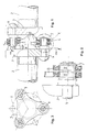
- a shaft joint in it 1 shown with the two shafts 2 torsionally rigid but inside certain limits axially and / or angularly movable with each other can be connected.
- a flange 3 is arranged, each of which in the illustrated embodiment three driving pins projecting axially towards the shaft joint 4 carries, the total of six driving pins, the are arranged alternately on gap, evenly on the circumference a common pitch circle 5 are arranged.
- the flanges 3 are - as Figure 3 shows more clearly - in the between the driving pin recessed circumferential areas, so in Principle star-shaped. Because of this star shape the opposite flanges with each other arranged on gap Poor can dip them into each other during angular movements, resulting in greater angular mobility of the shaft joint given is.
- the driving pin 4 at the ends of the Flange arms are alternated by a flexible, regular polygonal, preferably hexagonal joint ring 6 with each other non-rotatably connected, the one in the corner points with sockets 7, 7 'is provided.
- the lying between the sockets Legs of the joint ring are axially elastically deformable and twistable.
- the hinge ring itself is in several parts trained and by a wreath of several, two each Adjacent sleeves 7 and 7 or 7 'and 7' looping, in endless oval driving loops 8, 10, 10 'according to Art individual chain links assembled on the receptacles are each radially pivotable so that the hinge ring 6th is flexibly changeable in its shape.
- individual chain links assembled on the receptacles are each radially pivotable so that the hinge ring 6th is flexibly changeable in its shape.
- the axial bending and twisting of the individual slings this to the torque-related tensile loads additionally loaded by axial tilting and twisting, whereby the total load tolerable by the universal joints must be set accordingly lower.
- the driving loops 8, 10 axially pivotable mounted on the sleeves 7, 7 '.
- the oval slings directly or indirectly on the Driving pin 4 due to a pair of in meridian section round contact surfaces on the plug-in sleeve or on the driving loop stored.
- Embodiment is on the outside of the receptacles in each case a circumferential groove with a circular arc shape in cross section 11 attached, in the inside rounded rounded slings 8 intervene. This makes the slings 8 in the associated circumferential groove 11 with axial sliding movement of the loop cross section axially pivotable.
- a peripheral bead 17 provided in spherical shape 23 on the socket 7 ' which the driving loops 10 with a flat cross section, 10 'via an internally hollow spherical (24) sliding element 19 or 20 are stored indirectly.
- the driving loops 8 or 10, 10 'and the pressure bars 15, 15 ' are subject to tribological stress, but also the sleeves 7, 7 '.
- they are made from a low-friction and wear-resistant material, preferably made of a ceramic produced. It can be advantageous if in the ceramic material the sleeve particles of a solid lubricant are mixed in.
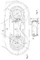
- each carry loop 8 or 10 10 'additionally a rectilinear pressure rod 15 or 15 'attached.
- the pressure rod 15 is on both ends provided with a saddle surface, both in terms of cross section as well as with respect to the circumferential course of the circumferential groove the receptacles is adapted.
- the pressure rod engages its two ends in the circumferential groove 11 each adjacent Receptacle 7 a.
- the pressure rods are in the axial direction directly form-fitting on the receptacles against slipping secured.
- torque load on the shaft joint take every second sling in a certain direction of rotation and the three inside the unloaded slings arranged push rods 15 on the torque transmission part.
- the three are under normal load conditions of the shaft joint Driving loops in one direction of rotation alone in able to transmit the occurring torque, so that in Normally the pressure rods do not need to be loaded. It is for the sake of static uncertainty not possible to torque on six power transmission elements to distribute a circle evenly, but only on three elements. It is therefore appropriate to the length L of the To dimension compression rods 15 so that they between the light space fill out two neighboring sockets 7 only with play 16 ( Figure 4). As a result, the pressure rods only come after a load-related elastic elongation of the slings for Only then carry and take on load.
- the game 16 of the pressure rods between two adjacent sockets dimensioned as large as the load-related elongation of the slings under a very high but tolerable in the long run Tensile stress.
- the foreheads Only when the torque load lead to a higher tensile load on the slings and this would stretch even more, the foreheads also lay down the pressure rods transmit power in the bottom of the circumferential grooves 11 of the sockets.
- the ones with convex flat sides 14 ' trained elastic driving loop 10 'naturally expands under load more than that with straight flat sides, so that the game with the elastic driving loops 10 'larger should be designed as for those with straight flat sides.
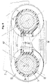
- the other exemplary embodiment is shown below 6 to 9, in which one in cross section - seen from the inside - concave circular contact surface 24 is provided on a sliding element 19 or 20, whereas a convex peripheral bead 17 is attached to the socket 7 ' is.
- the carry loop is indirectly connected supported by sliding elements 19 and 20 on the receptacle, which has the advantage that the material of the sliding elements after optimally selected or determined tribological aspects can be.
- the slide shoe 19 'for the compression rod 15' into the slide element 19 structurally integrated into a ring-shaped closed component.
- the entraining loop 10 is initially on the outside of the two Sliding elements each placed between the guide rims 22, with which the mutual distance between the two opposite Sliding elements is set.
- the sliding elements are expedient previously on the spherical peripheral beads 17 of the Plug sleeves 7 'have been clipped axially.
- Around the ends of the Insert the pressure rod 15 'into the sliding shoes can, is an axially exposed wall of the shoe slotted, so that this can be bent open Wall inserted the end of the pressure rod axially in the shoe can be.
- the individual parts of the articulated ring 6 into one in itself closed and manageable workpiece are all parts of the Joint ring embedded in a rubber-elastic mass of low hardness and completely enclosed by it.
Landscapes
- Engineering & Computer Science (AREA)
- General Engineering & Computer Science (AREA)
- Mechanical Engineering (AREA)
- Pivots And Pivotal Connections (AREA)
- Shafts, Cranks, Connecting Bars, And Related Bearings (AREA)
- Devices For Conveying Motion By Means Of Endless Flexible Members (AREA)
- Orthopedics, Nursing, And Contraception (AREA)
Abstract
Description
- Fig. 1
- eine seitliche Schnitt-Ansicht durch bzw. auf ein Wellengelenk,
- Fig. 2
- eine vergrößerte Einzeldarstellung der Einzelheit II aus Figur 1,
- Fig. 3
- eine axiale Ansicht auf den Wellenflansch der in Figur 1 links dargestellten Welle gemäß einem Schnitt entlang der Linie III-III,
- Fig. 4
- eine nochmals vergrößerte Einzeldarstellung einer Mitnahmeschlinge des Wellengelenkes nach Figur 1 in axialer Ansicht im Einbauzustand einschließlich eingefügtem Druckstab,
- Fig. 5
- eine Einzeldarstellung eines Druckstabes aus Figur 4 gemäß dortiger Schnittlinie V-V,
- Fig. 6
- eine vergrößerte Einzeldarstellung ähnlich der Darstellung gemäß Figur 2, jedoch von einem modifizierten Wellengelenk mit kugelflächenförmigem Umfangswulst auf der Steckhülse,
- Fig. 7
- eine vergrößerte, perspektivische Einzeldarstellung eines Gleitelementes mit integriertem Gleitschuh für einen Druckstab aus dem Wellengelenk nach Figur 6,
- Fig. 8
- eine Modifikation des Gleitelementes nach Figur 7, wobei das Gleitelement für die Mitnahmeschlinge und der Gleitschuh für den Druckstab baulich voneinander getrennt sind und
- Fig. 9
- eine ähnliche Schnittdarstellung wie Figur 4, jedoch von dem Wellengelenk nach Figur 6 in axialer Ansicht im Einbauzustand einschließlich eingefügtem Druckstab.
Claims (7)
- Wellengelenk zum drehsteifen aber innerhalb gewisser Grenzen axial und/oder winkelweglichen Verbinden zweier Wellen miteinander,mit an den Enden der beiden durch das Gelenk verbundenen Wellen jeweils angeordneten Flansche mit mehreren, vorzugsweise drei in Richtung zum Wellengelenk hin axial abragenden Mitnahmezapfen, wobei die insgesamt vorgesehehen, vorzugsweise sechs, gegenseitig auf Lücke angeordnete Mitnahmezapfen gleichmäßig am Umfang eines gemeinsamen Teilkreises an-geordnet sind,mit einem die Mitnahmezapfen untereinander drehstarr verbindenden flexiblen, regelmäßig polygonartigen, vorzugsweise sechseckigen, in den Eckpunkten mit Steckhülsen versehenen Gelenkring, der zwischen den Steckhülsen in sich axial elastische verformbar ist,wobei der Gelenkring seinerseits mehrteilig durch einen Kranz mehrerer, jeweils zwei benachbarte Steckhülsen umschlingender, in sich endloser, ovaler Mitnahmeschlingen gebildet ist, die auf den Steckhülsen jeweils radial verschwenkbar sind, so daß der Gelenkring in seiner Form gelenkig veränderbar ist,
dadurch gekennzeichnet,
daß im Inneren der ovalen Mitnahmeschlinge (8) jeweils ein geradliniger Druckstab (15) angebracht ist, der an seinen beiden Stirnenden zumindest mittelbar mit einer an die Steckhülsen angepaßten Stützfläche versehen ist. - Wellengelenk nach Anspruch 1,
dadurch gekennzeichnet,
daß die Druckstäbe (15, 15') nicht nur in Umfangsrichtung, sondern auch in Axialrichtung zumindest mittelbar formschlüssig auf den Steckhülsen (7, 7') zentriert, d.h. gegen axiales und peripheres Wegrutschen trotz relativer Gleitbewegung in beiden Richtungen gesichert sind. - Wellengelenk nach Anspruch 1,
dadurch gekennzeichnet,
daß an den gradlinig und rechtwinklig auf definierte Länge beschnittenen Enden der Druckstäbe (15') Gleitschuhe (19', 21) aus einem gleitfähigen Werkstoff, insbesondere aus Kunststoff aufgesteckt sind, die gemeinsam die Funktionslänge der Druckstäbe (15') bilden. - Wellengelenk nach Anspruch 1,
dadurch gekennzeichnet,
daß die Druckstäbe (15) aus langfaser-verstärktem Kunststoff gebildet sind, wobei die Langfasern alle parallel zueinander und zur Längsachse der Druckstäbe (15) liegen und unterbrechungsfrei durchlaufen. - Wellengelenk nach Anspruch 1,
dadurch gekennzeichnet,
daß in den Werkstoff der Druckstäbe (15), insbesondere in deren Faserwerkstoff und/oder den Matrix-Kunststoff oder in den Werkstoff der Gleitschuhe Partikel eines Festschmierstoffes eingemischt sind. - Wellengelenk nach Anspruch 1,
dadurch gekennzeichnet,
daß die wirksame Länge (L) der Druckstäbe (15) alleine oder - im Falle von endseitig aufgesteckten Gleitschuhen - der Druckstäbe einschließlich der Gleitschuhe (19', 21) so bemessen ist, daß sie den Lichtraum zwischen zwei benachbarten Steckhülsen (7, 7') nur mit Spiel (16) ausfüllen. - Wellengelenk nach Anspruch 6,
dadurch gekennzeichnet,
daß das Spiel (16) der Druckstäbe (15) zwischen zwei benachbarten Steckhülsen (7) so groß bemessen ist, daß sie bei Drehmomentbelastung des Wellengelenkes (1) sich kraftübertragend erst dann in den Grund der Umfangsrillen (11) bzw. der Oberfläche des Umfangswulstes der Steckhülsen (7) anlegen, wenn die Mitnahmeschlingen (8) durch die Drehmomentbelastung bereits bis zu einer bestimmten Umfangskraft belastet und in Umfangsrichtung elastisch gedehnt sind.
Applications Claiming Priority (4)
| Application Number | Priority Date | Filing Date | Title |
|---|---|---|---|
| DE19720857A DE19720857C2 (de) | 1997-05-17 | 1997-05-17 | Wellengelenk |
| DE19720857 | 1997-05-17 | ||
| DE19727321 | 1997-06-27 | ||
| DE19727321A DE19727321C2 (de) | 1997-05-17 | 1997-06-27 | Wellengelenk |
Publications (3)
| Publication Number | Publication Date |
|---|---|
| EP0878633A2 true EP0878633A2 (de) | 1998-11-18 |
| EP0878633A3 EP0878633A3 (de) | 2000-01-26 |
| EP0878633B1 EP0878633B1 (de) | 2004-12-08 |
Family
ID=26036650
Family Applications (1)
| Application Number | Title | Priority Date | Filing Date |
|---|---|---|---|
| EP98108045A Expired - Lifetime EP0878633B1 (de) | 1997-05-17 | 1998-05-02 | Wellengelenk |
Country Status (4)
| Country | Link |
|---|---|
| US (2) | US6176784B1 (de) |
| EP (1) | EP0878633B1 (de) |
| JP (1) | JP3315080B2 (de) |
| ES (1) | ES2232898T3 (de) |
Families Citing this family (10)
| Publication number | Priority date | Publication date | Assignee | Title |
|---|---|---|---|---|
| EP0878633B1 (de) * | 1997-05-17 | 2004-12-08 | DaimlerChrysler AG | Wellengelenk |
| DE10112260C1 (de) * | 2001-03-14 | 2003-01-16 | Sgf Gmbh & Co Kg | Drehelastische Wellenkupplung |
| US6905416B2 (en) * | 2002-01-03 | 2005-06-14 | Rexnord Industries, Inc. | Flexible coupling |
| DE202004014280U1 (de) * | 2004-09-10 | 2006-01-12 | Centa-Antriebe Kirschey Gmbh | Vorrichtung zur Übertragung von Drehmomenten |
| BRPI0520694B1 (pt) * | 2005-11-22 | 2019-02-05 | Volvo Lastvagnar Ab | motor de combustão interna com tubulação de gás de exaustão |
| US7824270B2 (en) * | 2007-01-23 | 2010-11-02 | C-Flex Bearing Co., Inc. | Flexible coupling |
| US20100227697A1 (en) * | 2009-03-04 | 2010-09-09 | C-Flex Bearing Co., Inc. | Flexible coupling |
| DE102011119936A1 (de) | 2011-12-01 | 2013-06-06 | SGF SüDDEUTSCHE GELENKSCHEIBENFABRIK GMBH & CO. KG | Elastisches Kraftübertragungsglied und Kupplungsvorrichtung |
| DE102019127763B4 (de) * | 2019-10-15 | 2023-09-07 | Hackforth Gmbh | Kupplung |
| CN112648298A (zh) * | 2020-12-28 | 2021-04-13 | 奇瑞汽车股份有限公司 | 车辆传动装置 |
Citations (2)
| Publication number | Priority date | Publication date | Assignee | Title |
|---|---|---|---|---|
| DE4140311A1 (de) | 1991-12-06 | 1993-06-09 | Gkn Automotive Ag, 5200 Siegburg, De | Wellenkupplungselement |
| DE4304274C1 (de) | 1993-02-12 | 1994-03-17 | Sgf Gmbh & Co Kg | Gelenkscheibe, insbesondere für den Antriebsstrang in Kraftfahrzeugen |
Family Cites Families (23)
| Publication number | Priority date | Publication date | Assignee | Title |
|---|---|---|---|---|
| US703582A (en) * | 1902-02-26 | 1902-07-01 | P H & F M Roots Company | Flexible shaft-coupling. |
| US903171A (en) * | 1905-10-21 | 1908-11-10 | Gen Electric | Flexible coupling. |
| US1114326A (en) * | 1912-11-04 | 1914-10-20 | Harry L Allen | Flexible coupling. |
| US1424051A (en) * | 1920-12-23 | 1922-07-25 | Herbert N Wayne | Universal joint |
| DE408277C (de) * | 1925-01-15 | Kirchbach & Co | Elastisches Kupplungsglied, insbesondere fuer Gelenkkupplungen bei Kraftfahrzeugen | |
| DE1040854B (de) | 1953-02-24 | 1958-10-09 | Eduard Erhardt Fa | Elastische Wellengelenkscheibe |
| US3362252A (en) * | 1965-10-21 | 1968-01-09 | Bendix Corp | Redundant connecting link |
| AU426511B2 (en) | 1967-11-06 | 1972-07-26 | Samuel Taylor Pty. Limited | Improvements in or relating to aerosol valves |
| GB1258849A (de) * | 1970-01-17 | 1971-12-30 | ||
| FR2204254A5 (en) | 1972-10-25 | 1974-05-17 | Kleber Colombes | Elastic coupling of fibre-contg rubber - with axial elasticity and circumfer-ential rigidity |
| JPS51143158A (en) * | 1975-06-04 | 1976-12-09 | Toyota Motor Corp | Flexible coupling for power transmission |
| JPS5285534A (en) | 1975-12-31 | 1977-07-15 | Showa Electric Wire & Cable Co | Sutomatic tape sinding machine |
| DE2622003C3 (de) * | 1976-05-18 | 1980-07-03 | Daimler-Benz Ag, 7000 Stuttgart | Elastische Wellenkupplung, insbesondere Kardanwellen-Kupplung für Kraftfahrzeuge |
| DE2705598C3 (de) * | 1977-02-10 | 1980-08-21 | Sgf Sueddeutsche Gelenkscheibenfabrik Gmbh & Co Kg, 8264 Waldkraiburg | Elastische Gelenkscheibe für Wellenkupplungen |
| DE2752445C2 (de) | 1977-11-24 | 1982-11-04 | Daimler-Benz Ag, 7000 Stuttgart | Elastische Gelenkscheibe für Wellenkupplungen |
| JPS5687632A (en) | 1979-12-18 | 1981-07-16 | Daido Steel Co Ltd | Atmosphere circulation type treating furnace |
| JPS5740135A (en) | 1980-08-22 | 1982-03-05 | Lord Corp | Power transmitting member |
| JPH0752427Y2 (ja) * | 1986-11-07 | 1995-11-29 | 東洋ゴム工業株式会社 | 高負荷トルク伝達用弾性継手 |
| JPH01106565A (ja) * | 1987-10-19 | 1989-04-24 | Omron Tateisi Electron Co | エンコーダと回転体の動力伝達構造 |
| EP0354868B1 (de) * | 1988-08-11 | 1994-12-21 | Addax, Inc. | Drehkupplung |
| US5033988A (en) * | 1989-03-07 | 1991-07-23 | Lord Corporation | Reversible endless belt rotary coupling |
| EP0878633B1 (de) * | 1997-05-17 | 2004-12-08 | DaimlerChrysler AG | Wellengelenk |
| DE29708814U1 (de) * | 1997-05-17 | 1997-07-17 | Mercedes-Benz Aktiengesellschaft, 70327 Stuttgart | Wellengelenk |
-
1998
- 1998-05-02 EP EP98108045A patent/EP0878633B1/de not_active Expired - Lifetime
- 1998-05-02 ES ES98108045T patent/ES2232898T3/es not_active Expired - Lifetime
- 1998-05-18 US US09/080,251 patent/US6176784B1/en not_active Expired - Fee Related
- 1998-05-18 JP JP15357498A patent/JP3315080B2/ja not_active Expired - Fee Related
-
2000
- 2000-12-29 US US09/750,356 patent/US6371858B2/en not_active Expired - Fee Related
Patent Citations (2)
| Publication number | Priority date | Publication date | Assignee | Title |
|---|---|---|---|---|
| DE4140311A1 (de) | 1991-12-06 | 1993-06-09 | Gkn Automotive Ag, 5200 Siegburg, De | Wellenkupplungselement |
| DE4304274C1 (de) | 1993-02-12 | 1994-03-17 | Sgf Gmbh & Co Kg | Gelenkscheibe, insbesondere für den Antriebsstrang in Kraftfahrzeugen |
Also Published As
| Publication number | Publication date |
|---|---|
| EP0878633B1 (de) | 2004-12-08 |
| EP0878633A3 (de) | 2000-01-26 |
| US6176784B1 (en) | 2001-01-23 |
| JPH1182533A (ja) | 1999-03-26 |
| JP3315080B2 (ja) | 2002-08-19 |
| US20010011038A1 (en) | 2001-08-02 |
| ES2232898T3 (es) | 2005-06-01 |
| US6371858B2 (en) | 2002-04-16 |
Similar Documents
| Publication | Publication Date | Title |
|---|---|---|
| DE3734089C2 (de) | Biegsame Welle-Kupplung zur Übertragung hoher Drehmomentlasten | |
| DE2452535B2 (de) | Rotorkopf für Drehflügelflugzeuge mit mindestens zwei einander gegenüberliegend angeordneten Rotorblättern | |
| EP3329145B1 (de) | Gurt oder gurtsegment | |
| EP0878633B1 (de) | Wellengelenk | |
| DE3431531A1 (de) | Energiezufuehrungskette | |
| DE1040854B (de) | Elastische Wellengelenkscheibe | |
| CH704969A1 (de) | Riemen mit einer lösbaren Endverbindung. | |
| EP3115640A1 (de) | Gurt oder gurtsegment | |
| EP2557327A1 (de) | Kupplungseinheit zur verbindung eines Antriebs mit einem Abtrieb | |
| WO2007090890A1 (de) | Verfahren zur herstellung einer schlingeneinheit | |
| DE2153411B2 (de) | Elastische klauenkupplung | |
| DE19727321C2 (de) | Wellengelenk | |
| DE2415911C3 (de) | Verbindungsglied für drehelastische Kupplungen | |
| EP2148106B1 (de) | Drehmomentübertragungseinrichtung | |
| DE10241753C1 (de) | Stator für Exzenterschneckenpumpe | |
| DE19738621C2 (de) | Wellengelenk | |
| DE19720857C2 (de) | Wellengelenk | |
| DE2920074A1 (de) | Elastische kupplung | |
| DE2844849A1 (de) | Drehelastische stoss- und schwingungsdaempfende kupplung | |
| DE19712302C2 (de) | Flexibles Kupplungselement | |
| DE3400918A1 (de) | Verbindung zum uebertragen von bewegung von einer antreibenden welle auf eine angetriebene welle | |
| DE3131694A1 (de) | "gelenkkupplung" | |
| EP1849723B1 (de) | Förderkette | |
| DE4303772A1 (de) | Bewegliche Laschenkupplung | |
| DE20002500U1 (de) | Energieführungskette |
Legal Events
| Date | Code | Title | Description |
|---|---|---|---|
| PUAI | Public reference made under article 153(3) epc to a published international application that has entered the european phase |
Free format text: ORIGINAL CODE: 0009012 |
|
| AK | Designated contracting states |
Kind code of ref document: A2 Designated state(s): DE ES FR GB IT SE |
|
| AX | Request for extension of the european patent |
Free format text: AL;LT;LV;MK;RO;SI |
|
| RAP1 | Party data changed (applicant data changed or rights of an application transferred) |
Owner name: DAIMLERCHRYSLER AG |
|
| PUAL | Search report despatched |
Free format text: ORIGINAL CODE: 0009013 |
|
| AK | Designated contracting states |
Kind code of ref document: A3 Designated state(s): AT BE CH CY DE DK ES FI FR GB GR IE IT LI LU MC NL PT SE |
|
| AX | Request for extension of the european patent |
Free format text: AL;LT;LV;MK;RO;SI |
|
| RIC1 | Information provided on ipc code assigned before grant |
Free format text: 7F 16D 3/62 A, 7F 16D 3/78 B |
|
| 17P | Request for examination filed |
Effective date: 20000129 |
|
| AKX | Designation fees paid |
Free format text: DE ES FR GB IT SE |
|
| GRAP | Despatch of communication of intention to grant a patent |
Free format text: ORIGINAL CODE: EPIDOSNIGR1 |
|
| GRAP | Despatch of communication of intention to grant a patent |
Free format text: ORIGINAL CODE: EPIDOSNIGR1 |
|
| GRAA | (expected) grant |
Free format text: ORIGINAL CODE: 0009210 |
|
| GRAS | Grant fee paid |
Free format text: ORIGINAL CODE: EPIDOSNIGR3 |
|
| AK | Designated contracting states |
Kind code of ref document: B1 Designated state(s): DE ES FR GB IT SE |
|
| REG | Reference to a national code |
Ref country code: GB Ref legal event code: FG4D Free format text: NOT ENGLISH |
|
| REF | Corresponds to: |
Ref document number: 59812346 Country of ref document: DE Date of ref document: 20050113 Kind code of ref document: P |
|
| REG | Reference to a national code |
Ref country code: SE Ref legal event code: TRGR |
|
| GBT | Gb: translation of ep patent filed (gb section 77(6)(a)/1977) |
Effective date: 20050310 |
|
| PG25 | Lapsed in a contracting state [announced via postgrant information from national office to epo] |
Ref country code: IT Free format text: LAPSE BECAUSE OF NON-PAYMENT OF DUE FEES Effective date: 20050502 Ref country code: GB Free format text: LAPSE BECAUSE OF NON-PAYMENT OF DUE FEES Effective date: 20050502 |
|
| PG25 | Lapsed in a contracting state [announced via postgrant information from national office to epo] |
Ref country code: SE Free format text: LAPSE BECAUSE OF NON-PAYMENT OF DUE FEES Effective date: 20050503 |
|
| PG25 | Lapsed in a contracting state [announced via postgrant information from national office to epo] |
Ref country code: ES Free format text: LAPSE BECAUSE OF NON-PAYMENT OF DUE FEES Effective date: 20050504 |
|
| REG | Reference to a national code |
Ref country code: ES Ref legal event code: FG2A Ref document number: 2232898 Country of ref document: ES Kind code of ref document: T3 |
|
| PLBE | No opposition filed within time limit |
Free format text: ORIGINAL CODE: 0009261 |
|
| STAA | Information on the status of an ep patent application or granted ep patent |
Free format text: STATUS: NO OPPOSITION FILED WITHIN TIME LIMIT |
|
| ET | Fr: translation filed | ||
| 26N | No opposition filed |
Effective date: 20050909 |
|
| PG25 | Lapsed in a contracting state [announced via postgrant information from national office to epo] |
Ref country code: DE Free format text: LAPSE BECAUSE OF NON-PAYMENT OF DUE FEES Effective date: 20051201 |
|
| EUG | Se: european patent has lapsed | ||
| GBPC | Gb: european patent ceased through non-payment of renewal fee |
Effective date: 20050502 |
|
| REG | Reference to a national code |
Ref country code: ES Ref legal event code: FD2A Effective date: 20050504 |
|
| REG | Reference to a national code |
Ref country code: FR Ref legal event code: ST Effective date: 20080229 |
|
| PG25 | Lapsed in a contracting state [announced via postgrant information from national office to epo] |
Ref country code: FR Free format text: LAPSE BECAUSE OF NON-PAYMENT OF DUE FEES Effective date: 20050531 |