EP0878633A2 - Shaft coupling - Google Patents
Shaft coupling Download PDFInfo
- Publication number
- EP0878633A2 EP0878633A2 EP98108045A EP98108045A EP0878633A2 EP 0878633 A2 EP0878633 A2 EP 0878633A2 EP 98108045 A EP98108045 A EP 98108045A EP 98108045 A EP98108045 A EP 98108045A EP 0878633 A2 EP0878633 A2 EP 0878633A2
- Authority
- EP
- European Patent Office
- Prior art keywords
- shaft joint
- pressure rods
- driving
- joint according
- torque
- Prior art date
- Legal status (The legal status is an assumption and is not a legal conclusion. Google has not performed a legal analysis and makes no representation as to the accuracy of the status listed.)
- Granted
Links
Images

Classifications
-
- F—MECHANICAL ENGINEERING; LIGHTING; HEATING; WEAPONS; BLASTING
- F16—ENGINEERING ELEMENTS AND UNITS; GENERAL MEASURES FOR PRODUCING AND MAINTAINING EFFECTIVE FUNCTIONING OF MACHINES OR INSTALLATIONS; THERMAL INSULATION IN GENERAL
- F16D—COUPLINGS FOR TRANSMITTING ROTATION; CLUTCHES; BRAKES
- F16D3/00—Yielding couplings, i.e. with means permitting movement between the connected parts during the drive
- F16D3/50—Yielding couplings, i.e. with means permitting movement between the connected parts during the drive with the coupling parts connected by one or more intermediate members
- F16D3/78—Yielding couplings, i.e. with means permitting movement between the connected parts during the drive with the coupling parts connected by one or more intermediate members shaped as an elastic disc or flat ring, arranged perpendicular to the axis of the coupling parts, different sets of spots of the disc or ring being attached to each coupling part, e.g. Hardy couplings
-
- F—MECHANICAL ENGINEERING; LIGHTING; HEATING; WEAPONS; BLASTING
- F16—ENGINEERING ELEMENTS AND UNITS; GENERAL MEASURES FOR PRODUCING AND MAINTAINING EFFECTIVE FUNCTIONING OF MACHINES OR INSTALLATIONS; THERMAL INSULATION IN GENERAL
- F16D—COUPLINGS FOR TRANSMITTING ROTATION; CLUTCHES; BRAKES
- F16D3/00—Yielding couplings, i.e. with means permitting movement between the connected parts during the drive
- F16D3/50—Yielding couplings, i.e. with means permitting movement between the connected parts during the drive with the coupling parts connected by one or more intermediate members
- F16D3/60—Yielding couplings, i.e. with means permitting movement between the connected parts during the drive with the coupling parts connected by one or more intermediate members comprising pushing or pulling links attached to both parts
- F16D3/62—Yielding couplings, i.e. with means permitting movement between the connected parts during the drive with the coupling parts connected by one or more intermediate members comprising pushing or pulling links attached to both parts the links or their attachments being elastic
-
- F—MECHANICAL ENGINEERING; LIGHTING; HEATING; WEAPONS; BLASTING
- F16—ENGINEERING ELEMENTS AND UNITS; GENERAL MEASURES FOR PRODUCING AND MAINTAINING EFFECTIVE FUNCTIONING OF MACHINES OR INSTALLATIONS; THERMAL INSULATION IN GENERAL
- F16D—COUPLINGS FOR TRANSMITTING ROTATION; CLUTCHES; BRAKES
- F16D3/00—Yielding couplings, i.e. with means permitting movement between the connected parts during the drive
- F16D3/50—Yielding couplings, i.e. with means permitting movement between the connected parts during the drive with the coupling parts connected by one or more intermediate members
- F16D3/72—Yielding couplings, i.e. with means permitting movement between the connected parts during the drive with the coupling parts connected by one or more intermediate members with axially-spaced attachments to the coupling parts
- F16D3/725—Yielding couplings, i.e. with means permitting movement between the connected parts during the drive with the coupling parts connected by one or more intermediate members with axially-spaced attachments to the coupling parts with an intermediate member made of fibre-reinforced resin
Landscapes
- Engineering & Computer Science (AREA)
- General Engineering & Computer Science (AREA)
- Mechanical Engineering (AREA)
- Pivots And Pivotal Connections (AREA)
- Shafts, Cranks, Connecting Bars, And Related Bearings (AREA)
- Devices For Conveying Motion By Means Of Endless Flexible Members (AREA)
- Orthopedics, Nursing, And Contraception (AREA)
Abstract
Description
Die Erfindung geht aus von einem Wellengelenk nach dem Oberbegriff von Anspruch 1, wie es beispielsweise aus der DE 43 04 274 C1 als bekannt hervorgeht.The invention is based on a shaft joint according to the preamble of claim 1, as for example from DE 43 04 274 C1 emerges as known.
Derartige Wellengelenke werden beim Einsatz in Fahrzeugen nicht nur mechanisch sehr stark durch durch Drehmomentspitzen und durch spannungsüberhöhende Gelenkbewegungen belastet, sondern es tritt durch Wärmeleitung und durch Wärmeabstrahlung in der Nähe befindlicher, z.T. sehr heißer Teile auch eine thermische Belastung des Wellengelenkes auf. Durch die Bauteilerwärmung wird bei Kunststoffteilen die Belastbarkeit der eingesetzten Werkstoffe herabgesetzt, so daß auch die thermische Belastung der Wellengelenke für deren mechanische Belastbarkeit relevant ist.Such universal joints are not used in vehicles only mechanically very strong due to torque peaks and stressed by stress-increasing joint movements, but it occurs through heat conduction and through heat radiation in the Nearby, sometimes very hot parts also thermal Load on the shaft joint. Through component heating the resilience of the used plastic parts Materials reduced so that the thermal load of the universal joints relevant for their mechanical resilience is.
Viele bekannte Wellengelenke, wie sie insbesondere für Leichtbaukonstruktionen von Gelenkwellen vorgesehen sind, weisen an den Enden der beiden durch das Gelenk verbundenen Wellen jeweils Flansche mit drei in Richtung zum Wellengelenk hin axial abragenden Mitnahmezapfen auf, wobei die insgesamt sechs, gegenseitig auf Lücke angeordnete Mitnahmezapfen gleichmäßig am Umfang eines gemeinsamen Teilkreises angeordnet sind. Die Mitnahmezapfen sind durch einen flexiblen, sechseckigen, in den Eckpunkten mit Steckhülsen versehenen Gelenkring untereinander drehstarr verbunden. Der Gelenkring ist zwischen den Steckhülsen in sich axial elastische verformbar, so daß die beiden über den Gelenkring verbundenen Flansche - begrenzte - Winkelbewe-gungen in jeder beliebigen Richtung, auch während der Drehung ausführen können. Durch diese Winkelbewegung wird der Gelenkring axial gewellt, wodurch im Rahmen der Elastizität entsprechend des Hook'schen Gesetzes Biegespannungen entstehen, die sich den drehmomentbedingten Betriebsbeanspruchungen überlagern. Durch diese Überlagerung von Beanspruchungen kann die Werkstoff-Festigkeit erreicht werden. Demgemäß können aus Gründen der Dauerfestigkeit der Wellengelenke nur beschränkte Beugewinkel zugelassen werden.Many well-known universal joints, such as those used especially for lightweight constructions of propeller shafts are provided the ends of the two shafts connected by the joint Flanges with three axially towards the shaft joint protruding drive pins on, the total of six, mutually drive pins arranged on a gap evenly on the Scope of a common pitch circle are arranged. The driving pin are characterized by a flexible, hexagonal, in the Articulated ring provided with corner sleeves with each other torsionally rigid. The joint ring is between the receptacles axially elastic deformable in itself, so that the two over flanges connected to the joint ring - limited - angular movements in any direction, even while rotating can execute. Through this angular movement, the joint ring axially corrugated, which in accordance with the elasticity accordingly of Hook 's law, bending stresses arise overlap the torque-related operating stresses. Through this superposition of stresses Material strength can be achieved. Accordingly, for reasons the flexural strength of the universal joints only has limited flexion angles be allowed.
Die Anzahl von drei Mitnahmezapfen je Flansch, also insgesamt sechs Mitnahmezapfen im Wellengelenk ist nicht zwingend erforderlich. Es sind auch nur zwei Zapfen je Flansch, also insgesamt vier Mitnahmezapfen denkbar, wobei jedoch aufgrund der Verteilung der Umfangsbelastung auf diese geringe Zahl von Mitnahmeelementen diese stärker beansprucht sind als bei einer höheren Anzahl von Mitnehmern. Auch vier oder mehr Zapfen je Flansch, also insgesamt acht oder mehr Mitnahmezapfen im Wellengelenk sind möglich, wobei mit zunehmender Anzahl von Mitnahmezapfen der erforderliche Gelenkdurchmesser größer und/oder der tolerierbare Beugewinkel kleiner wird. Deshalb ist als am häufigsten anzutreffender Kompromiß zwischen Einzelteilbelastung einerseits und Gelenkgröße andererseits die angesprochene Anzahl von drei bzw. sechs Mitnahmezapfen anzutreffen.The number of three driving pins per flange, in total six driving pins in the shaft joint are not absolutely necessary. There are also only two pegs per flange, in total four driving pins conceivable, but due to the Distribution of the circumferential load on this small number of driving elements these are more stressed than a higher one Number of carriers. Also four or more cones each Flange, i.e. a total of eight or more driving pins in the shaft joint are possible, with increasing number of driving pins the required joint diameter is larger and / or the tolerable flexion angle becomes smaller. Therefore, as on most common compromise between item loading on the one hand and joint size on the other hand the one addressed Number of three or six driving pins can be found.
Die DE 41 40 311 A1 zeigt einen sechseckigen Gelenkring aus Faserverbundmaterial in Form einer Ringscheibe, bei dem in den verstärkten Eckbereichen axiale Steckhülsen eingelassen sind. Die geradlinigen Bereiche zwischen zwei benachbarten Ecken sind durch einen relativ dünnen, in der Ebene der Ringscheibe sich erstreckenden Steg aus mehreren zusammenhängenden Lagen von ausgehärtetem Faserverbundmaterial gebildet. Dieser Steg ist in Radialrichtung relativ breit. Beim Beugen des Wellengelenkes werden diese Stege nicht nur gebogen sondern auch verdrillt. Zwar lassen sich die dünnen Stege bei relativ geringen BiegeSpannungen elastisch verbiegen, jedoch treten wegen der von einer Rotationssymmetrie stark abweichenden Form der Stege beim Verdrillen derselben vor allem an ihrem inneren und äußeren Rand hohe Spannungen auf. DE 41 40 311 A1 shows a hexagonal joint ring made of fiber composite material in the form of an washer, in which in the Reinforced corner areas are inserted axial sleeves. The straight-line areas are between two adjacent corners through a relatively thin, in the plane of the washer itself extending web of several contiguous layers of cured fiber composite material is formed. This bridge is in Radial direction relatively wide. When bending the shaft joint these bars are not only bent but also twisted. The thin webs can be used at relatively low bending stresses bend elastically, but occur because of one Rotational symmetry of the webs at the Twisting them especially on their inner and outer Edge high tensions.
Die eingangs genannte DE 43 04 274 C1 zeigt einen sechseckigen Gelenkring, bei dem die in den Eckbereichen angeordneten Steckhülsen paarweise jeweils durch in sich endlose, ovale Mitnahmeschlingen miteinander verbunden sind, die um zwei benachbarte Steckhülsen außenseitig herumgeschlungen sind. Und zwar sind abwechselnd breite, mittig liegende Mitnahmeschlingen und ein Paar randseitig liegende schmalere Mitnahmeschlingen im Gelenkring angeordnet. Die breite Mitnahmeschlinge ist etwa dreimal so breit wie ihre radiale Wandstärke mißt; die beiden schmalen Mitnahmeschlingen sind gemeinsam etwa ebenso breit wie die mittig liegende Mitnahmeschlinge. Die Mitnahmeschlingen sind auf den Steckhülsen radial verschwenkbar, so daß der Gelenkring als Einzelteil in seiner Form gelenkig veränderbar ist. Zum Zusammenhalten aller Teile des Gelenkringes und zur Verhinderung von Schmutzzutritt sind die Teile des Gelenkringes in eine gummielastische Masse geringer Härte eingebettet und vollständig um-schlossen. Aufgrund der in Relation zur axial gemessenen Breite der Mitnahmeschlingen relativ geringen radialen Wandstärke bieten sie gute Voraussetzungen für eine Aufnahme des Umfangszuges bei geringen Spannungsüberhöhungen in den Krümmungen der Mitnahmeschlingen. Allerdings werden beim Beugen dieses Wellengelenkes die Mitnahmeschlingen in Axialrichtung verkantet oder gekippt und außerdem verdrillt, wobei an unterschiedlichen Stellen der Mitnahmeschlingen starke Spannungsüberhöhungen auftreten. Beim Verkanten kommt es zu einer einseitigen Kantenauflage der Schlingenkrümmung auf der Steckhülse und dementsprechend dort zu einer Spannungskonzentration. Beim Verdrillen der relativ breiten Mitnahmeschlingen treten - ähnlich wie bei den Stegen der zuvor geschilderten Gelenkscheibe nach der DE 41 40 311 A1 - an den Rändern Spannugsüberhöhungen wenn auch auf ge-ringerem Niveau als dort auf. Es treten also im Betrieb selbst bei mäßiger Drehmomentbelastung zumindest bei spürbaren Abwinklungen des Wellengelenkes lokal hohe Spannungen in den Mitnahmeschlingen auf, die die dauerhaft tolerierbare Nennbelastung des Wellengelenkes herabsetzen. The aforementioned DE 43 04 274 C1 shows a hexagonal Articulated ring, in which the sockets arranged in the corner areas in pairs, each with endless oval loops are connected to each other by two neighboring ones Sockets are looped around on the outside. And are alternately wide, centrally located slings and a Pair of narrower slings in the hinge ring on the edge arranged. The wide carry loop is about three times as wide as their radial wall thickness measures; the two narrow Take-along slings are about the same width as the middle lying sling. The takeaways are open the receptacles radially pivoted so that the joint ring as Item is articulately changeable in its shape. To hold together all parts of the joint ring and to prevent Dirt are the parts of the joint ring in a rubber elastic Mass of low hardness embedded and completely enclosed. Due to the relative to the axially measured width the slings offer relatively small radial wall thickness they are good prerequisites for taking up the extensive train with slight tension increases in the curvatures of the driving loops. However, when bending this shaft joint the driving loops canted in the axial direction or tilted and also twisted, with different Excessive tension increases occur in the driving loops. When tilting, there is a one-sided edge support the loop curvature on the receptacle and accordingly there to a stress concentration. When twisting the relatively wide slings - similar to the Webs of the previously described joint disk according to DE 41 40 311 A1 - tension increases at the edges, albeit at a lower rate Level than up there. So it occurs in the company itself with moderate torque load, at least with noticeable bends of the shaft joint locally high tensions in the driving loops on that the permanently tolerable nominal load lower the shaft joint.
Aufgabe der Erfindung ist es, das gattungsgemäß zugrundegelegte Wellengelenk dahingehend zu verbessern, daß höhere, dauerhaft zulässige Drehmomentbelastungen und/oder Beugewinkel zugelassen werden können.The object of the invention is that of the generic type Improve shaft joint to be higher, permanent permissible torque loads and / or flexion angles permitted can be.
Diese Aufgabe wird - ausgehend von dem gattungsgemäß zugrundegelegten Wellengelenk - erfindungsgemäß durch die kennzeichnenden Merkmale von Anspruch 1 gelöst. Aufgrund der Druckstäbe im Inneren der Mitnahmeschlingen tragen in jeder Beanspruchungsrichtung insgesamt doppelt soviele Kraftübertragungselemente wie Mitnahmeschlingen für jeweils eine Drehrichtung vorgesehen sind oder - anders ausgedrückt - es tragen ebenso viele Kraftübertragungselemente wie Mitnahmezapfen im Gelenk enthalten sind. Und zwar trägt in jeder Beanspruchungsrichtung nach wie vor jede zweite Mitnahmeschlinge, zusätzlich tragen aber noch die dazwischen liegenden, in den unbelasteten Mitnahmeschlingen angeordneten Druckstäbe. Aufgrund einer Verdoppelung der Kraftübertragungselemente kann gegenüber dem Stand der Technik eine deutlich höhere Nennlast des Wellengelenkes dauerhaft zugelassen werden.This task is - starting from the generic one Shaft joint - according to the invention by the characteristic Features of claim 1 solved. Due to the pressure rods in the Inside of the slings carry in every direction a total of twice as many power transmission elements like slings for each direction of rotation are or - in other words - just as many power transmission elements like driving pins in the joint are. And that continues in every direction in front of every second sling, but also carry it the intermediate, in the unloaded slings arranged pressure rods. Due to a doubling of the Power transmission elements can be compared to the prior art permanently permitted a significantly higher nominal load of the shaft joint will.
Zweckmäßige Ausgestaltungen der Erfindung können den Unteransprüchen entnommen werden; im übrigen ist die Erfindung anhand eines in der Zeichnung dargestellten Ausführungsbeispieles nachfolgend noch erläutert; dabei zeigen:
- Fig. 1
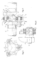
- eine seitliche Schnitt-Ansicht durch bzw. auf ein Wellengelenk,
- Fig. 2
- eine vergrößerte Einzeldarstellung der Einzelheit II aus Figur 1,
- Fig. 3
- eine axiale Ansicht auf den Wellenflansch der in Figur 1 links dargestellten Welle gemäß einem Schnitt entlang der Linie III-III,
- Fig. 4
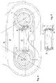
- eine nochmals vergrößerte Einzeldarstellung einer Mitnahmeschlinge des Wellengelenkes nach Figur 1 in axialer Ansicht im Einbauzustand einschließlich eingefügtem Druckstab,
- Fig. 5
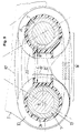
- eine Einzeldarstellung eines Druckstabes aus
Figur 4 gemäß dortiger Schnittlinie V-V, - Fig. 6
- eine vergrößerte Einzeldarstellung ähnlich der Darstellung
gemäß
Figur 2, jedoch von einem modifizierten Wellengelenk mit kugelflächenförmigem Umfangswulst auf der Steckhülse, - Fig. 7
- eine vergrößerte, perspektivische Einzeldarstellung eines
Gleitelementes mit integriertem Gleitschuh für einen
Druckstab aus dem Wellengelenk nach
Figur 6, - Fig. 8
- eine Modifikation des Gleitelementes nach
Figur 7, wobei das Gleitelement für die Mitnahmeschlinge und der Gleitschuh für den Druckstab baulich voneinander getrennt sind und - Fig. 9
- eine ähnliche Schnittdarstellung wie
Figur 4, jedoch von dem Wellengelenk nachFigur 6 in axialer Ansicht im Einbauzustand einschließlich eingefügtem Druckstab.
- Fig. 1
- a side sectional view through or on a shaft joint,
- Fig. 2
- 2 shows an enlarged individual representation of detail II from FIG. 1,
- Fig. 3
- 3 shows an axial view of the shaft flange of the shaft shown on the left in FIG. 1 according to a section along the line III-III,
- Fig. 4
- 2 shows an enlarged individual representation of a driving loop of the shaft joint according to FIG. 1 in an axial view in the installed state including the inserted compression rod,
- Fig. 5
- 4 shows an individual representation of a pressure rod from FIG. 4 according to section line VV there,
- Fig. 6
- 3 shows an enlarged individual illustration similar to the illustration according to FIG. 2, but of a modified shaft joint with a spherical surface-shaped bulge on the plug-in sleeve,
- Fig. 7
- 6 shows an enlarged, perspective individual illustration of a sliding element with an integrated sliding shoe for a compression rod from the shaft joint according to FIG. 6,
- Fig. 8
- a modification of the sliding element according to Figure 7, wherein the sliding element for the driving loop and the sliding shoe for the pressure rod are structurally separated from each other and
- Fig. 9
- a sectional view similar to Figure 4, but of the shaft joint of Figure 6 in an axial view in the installed state including inserted compression rod.
Es Sei zunächst auf die Gemeinsamkeit der beiden Ausführungsbeispiele
nach den Figuren 1 bis 5 zum einen bzw. den Figuren 6
bis 9 zum anderen eingegangen. Beide Ausführungsbeispiele bauen
auf der Darstellung nach Figur 1 auf. Darin ist ein Wellengelenk
1 gezeigt, mit dem zwei Wellen 2 drehsteif aber innerhalb
gewisser Grenzen axial und/oder winkelweglichen miteinander
verbunden werden können. An den Enden der beiden durch das Gelenk
verbundenen Wellen ist jeweils ein Flansch 3 angeordnet,
von denen jeder beim dargestellten Ausführungsbeispiel jeweils
drei in Richtung zum Wellengelenk hin axial abragende Mitnahmezapfen
4 trägt, wobei die insgesamt sechs Mitnahmezapfen, die
wechselseitig auf Lücke angeordnet sind, gleichmäßig am Umfang
eines gemeinsamen Teilkreises 5 angeordnet sind. Die Flansche 3
sind - wie Figur 3 deutlicher zeigt - in dem zwischen den Mitnahmezapfen
liegenden Umfangsbereichen ausgespart, also im
Prinzip sternförmig ausgebildet. Aufgrund dieser Sternform der
gegenüberliegenden Flansche mit gegenseitig auf Lücke angeordneten
Armen können diese bei Winkelbewegungen ineinander eintauchen,
wodurch eine größere Winkelbeweglichkeit des Wellengelenkes
gegeben ist. Die Mitnahmezapfen 4 an den Enden der
Flanscharme sind wechselweise durch einen flexiblen, regelmäßig
polygonartigen, vorzugsweise sechseckigen Gelenkring 6 untereinander
drehstarr verbunden, der in den Eckpunkten mit Steckhülsen
7, 7' versehen ist. Die zwischen den Steckhülsen liegenden
Schenkel des Gelenkringes sind in sich axial elastisch verformbar
und verdrillbar. Der Gelenkring seinerseits ist mehrteilig
ausgebildet und durch einen Kranz mehrerer, jeweils zwei
benachbarte Steckhülsen 7 und 7 bzw. 7' und 7' umschlingender,
in sich endloser, ovaler Mitnahmeschlingen 8, 10, 10' nach Art
einzelner Kettenglieder zusammengesetzt, die auf den Steckhülsen
jeweils radial verschwenkbar sind, so daß der Gelenkring 6
in seiner Form gelenkig veränderbar ist. Allerdings werden
durch die axiale Verbiegung und Verdrillung der einzelnen Mitnahmeschlingen
diese zu den drehmomentbedingten Zugbelastungen
zusätzlich durch axiales Verkanten und durch Verdrillen belastet,
wodurch die vom Wellengelenke tolerierbare Gesamtbelastung
entsprechend niedriger angesetzt werden muß.First, let us look at the commonality of the two exemplary embodiments
according to FIGS. 1 to 5 on the one hand or FIGS. 6
to 9 received another. Build both embodiments
on the representation of Figure 1. There is a shaft joint in it
1 shown, with the two
Um das Wellengelenk während der Rotation ohne weiteres relativ
stark abwinkeln zu können, sind bei den dargestellten Ausführungsbeispielen
die Mitnahmeschlingen 8, 10 axial schwenkbar
auf den Steckhülsen 7, 7' gelagert. Zu diesem Zweck sind die
ovalen Mitnahmeschlingen mittelbar oder unmittelbar auf den
Mitnahmezapfen 4 aufgrund eines Paares von im Meridianschnitt
runden Berührungsflächen an der Steckhülse bzw. an der Mitnahmeschlinge
gelagert. Bei dem in den Figuren 1 bis 5 dargestellten
Ausführungsbeispiel ist auf der Außenseite der Steckhülsen
jeweils eine im Querschnitt kreisbogenförmig gestaltete Umfangsrille
11 angebracht, in die innenseitig verrundete Mitnahmeschlingen
8 eingreifen. Dadurch sind die Mitnahmeschlingen 8
in der jeweils zugehörigen Umfangsrille 11 unter axialer Gleitbewegung
des Schlingenquerschnittes axial verschwenkbar. Beim
Ausführungsbeispiel nach den Figuren 6 bis 9 ist ein Umfangswulst
17 in Kugelform 23 auf der Steckhülse 7' vorgesehen, auf
dem die im Querschnitt flach gestalteten Mitnahmeschlingen 10,
10' über ein innenseitig hohlkugelförmiges (24) Gleitelement 19
bzw. 20 mittelbar gelagert sind.Relatively relative to the shaft joint during rotation
To be able to bend strongly are in the illustrated embodiments
the driving
Sowohl die Mitnahmeschlingen 8, 10 als auch die noch näher zu
beschreibenden Druckstäbe 15, 15' sind zweckmäßigerweise aus
langfaser-verstärktem Kunststoff gebildet, wobei die Langfasern
alle parallel zueinander und zum Verlauf des tragenden Querschnittes
liegen und unterbrechungsfrei durchlaufen. Die Mitnahmeschlingen
8, 10, 10' und die Druckstäbe 15, 15' führen
während des Rotierens des Wellengelenkes in abgewinkeltem Zustand
bei jeder Umdrehung eine vollständige Pendelbewegung in
axialer Richtung aus, wobei die kreisbogenförmig konturierten
Kontaktflächen axial aufeinander gleiten. Um bei dieser Gleitbewegung
einen Verschleiß möglichst zu vermeiden, sind in den
Faserwerkstoff und/oder den Matrix-Kunststoff der Mitnahmeschlingen
8, 10 und der Druckstäbe 15 Partikel eines Festschmierstoffes
eingemischt.Both the carry slings 8, 10 and the ones closer to
descriptive pressure bars 15, 15 'are expediently
Long fiber reinforced plastic is formed, the long fibers
all parallel to each other and to the course of the load-bearing cross-section
lie and go through uninterrupted. The
Nicht nur die Mitnahmeschlingen 8 bzw. 10, 10' und die Druckstäbe
15, 15' unterliegen einer tribologischen Beanspruchung,
sonder auch die Steckhülsen 7, 7'. Um auch bei ihnen einen Verschleiß
zu minimieren, werden sie aus einem reibungsarmen und
verschleißbeständigen Werkstoff, vorzugsweise aus einer Keramik
hergestellt. Dabei kann es von Vorteil sein, wenn in den Keramikwerkstoff
der Steckhülse Partikel eines Festschmierstoffes
eingemischt sind.Not only the driving
Um die Mitnahmeschlingen im Hinblick auf eine stoßartige Belastung zu optimieren, ist es gemäß der strichpunktierten Darstellung in Figur 9 zweckmäßig, die Flachseiten 14' des Ovals der Mitnahmeschlinge 10' gekrümmt auszubilden. Dadurch können sich die gekrümmten Flachseiten bei stoßartiger Zugbelastung der Mitnahmeschlinge elastisch in Richtung geradlinig strecken und zeitlich die Spannungsspitze abbauen. An sich wäre es auch denkbar, die Flachseiten ins innere des Ovals hinein zu wölben, was diese Wirkung ebenfalls hervorbrächte. Aus Gründen einer besseren Herstellbarkeit der Mitnahmeschlingen aus einem endlos-faserverstärktem Kunststoff im Wege der Wickeltechnik ist es jedoch zweckmäßiger, wenn die gekrümmten Flachseiten 14' des Ovals nach außen konvex gekrümmt sind. Selbstverständlich ist die ovale Formgebung ohne weiteres auch beim Ausführungsbeispiel nach den Figuren 1 bis 5 realisierbar.To take the slings with regard to a sudden load To optimize, it is according to the dash-dotted line useful in Figure 9, the flat sides 14 'of the oval of the driving loop 10 'to be curved. This allows the curved flat sides with shock-like tensile load stretch the sling elastically in a straight line and reduce the voltage spike in time. In itself, it would be too conceivable to arch the flat sides inside the oval, which would also produce this effect. For the sake of one better manufacture of the slings from an endless fiber-reinforced Plastic is in the way of winding technology however, it is more convenient if the curved flat sides 14 'of the Ovals are convexly curved outwards. It goes without saying the oval shape easily in the embodiment realizable according to Figures 1 to 5.
Obwohl insgesamt sechs Mitnahmeschlingen 8 in dem Wellengelenk
angebracht sind, trägt in jeder Drehrichtung jeweils nur die
halbe Anzahl von Mitnahmeschlingen zur Drehmomentübertragung
bei. Um eine Entlastung der Mitnahmeschlingen zu bewirken, ist
erfindungsgemäß im Inneren einer jeden Mitnahmeschlinge 8 bzw.
10, 10' zusätzlich noch je ein geradliniger Druckstab 15 bzw.
15' angebracht. Beim Ausführungsbeispiel nach den Figuren 1 bis
5 greift der Druckstab 15 mit seinen Stirnseiten ebenfalls in
die Umfangsrille 11 der Steckhülsen 7 kraftübertragend ein. Zu
diesem Zweck ist der Druckstab 15 an seinen beiden Stirnseiten
mit einer Sattelfläche versehen, die sowohl bezüglich des Querschnittes
als auch bezüglich des Umfangsverlaufes der Umfangsrille
der Steckhülsen angepaßt ist. Der Druckstab greift mit
seinen beiden Enden in die Umfangsrille 11 je einer angrenzenden
Steckhülse 7 ein. Dadurch sind die Druckstäbe in Axialrichtung
unmittelbar formschlüssig auf den Steckhülsen gegen Wegrutschen
gesichert. Bei Drehmomentbelastung des Wellengelenkes
in einer bestimmten Drehrichtung nehmen jede zweite Mitnahmeschlinge
und die drei im Inneren der unbelasteten Mitnahmeschlingen
angeordneten Druckstäbe 15 an der Drehmomentübertragung
teil. Durch diese Verteilung der Last auf eine doppelt so
hohe Anzahl von Kraftübertragungselementen wie im Stand der
Technik kommt es zu einer deutlichen Entlastung der Kraftübertragungselemente
im Wellengelenk.Although a total of six driving
Unter normalen Lastbedingungen des Wellengelenkes sind die drei
Mitnahmeschlingen einer Drehrichtung ohne weiteres alleine in
der Lage, das auftretende Drehmoment zu Übertragen, so daß im
Normalfall die Druckstäbe nicht belastet zu werden brauchen. Es
ist aus Gründen einer statischen Unbestimmtheit im übrigen
nicht möglich, ein Drehmoment auf sechs Kraftübertragungselemente
eines Kreises gleichmäßig zu verteilen, sondern nur auf
drei Elemente. Es ist deshalb zweckmäßig, die Länge L der
Druckstäbe 15 so zu bemessen, daß sie den Lichtraum zwischen
zwei benachbarten Steckhülsen 7 nur mit Spiel 16 (Figur 4) ausfüllen.
Dadurch kommen die Druckstäbe erst nach einer belastungsbedingten
elastischen Längung der Mitnahmeschlingen zum
Tragen und nehmen erst dann ebenfalls Last auf. Demgemäß ist
das Spiel 16 der Druckstäbe zwischen zwei benachbarten Steckhülsen
so groß bemessen, wie die lastbedingte Längung der Mitnahmeschlingen
unter einer zwar sehr hohen aber auf Dauer tolerierbaren
Zugbeanspruchung. Erst wenn die Drehmomentbelastung
zu einer höheren Zugbeanspruchung der Mitnahmeschlingen führen
und diese noch mehr dehnen würde, legen sich auch die Stirnenden
der Druckstäbe kraftübertragend in den Grund der Umfangsrillen
11 der Steckhülsen an. Die mit konvexen Flachseiten 14'
ausgebildeten elastische Mitnahmeschlinge 10' dehnt sich natürlich
unter Last mehr als die mit geradlinigen Flachseiten, so
daß das Spiel bei den elastischen Mitnahmeschlingen 10' größer
gestaltet werden müßte, als bei denen mit geradlinigen Flachseiten.The three are under normal load conditions of the shaft joint
Driving loops in one direction of rotation alone in
able to transmit the occurring torque, so that in
Normally the pressure rods do not need to be loaded. It
is for the sake of static uncertainty
not possible to torque on six power transmission elements
to distribute a circle evenly, but only on
three elements. It is therefore appropriate to the length L of the
To
Nachfolgend sei noch auf das andere Ausführungsbeispiel nach
den Figuren 6 bis 9 eingegangen, bei dem eine im Querschnitt -
von innen gesehen - konkav gestaltete kreisbogenförmige Kontaktfläche
24 an einem Gleitelement 19 bzw. 20 vorgesehen ist,
wogegen auf der Steckhülse 7' ein konvexer Umfangswulst 17 angebracht
ist. Bei dem Ausführungsbeispiel nach den Figuren 6
bis 9 ist die Mitnahmeschlinge mittelbar unter Zwischenschaltung
von Gleitelementen 19 bzw. 20 auf der Steckhülse gelagert,
was den Vorteil hat, daß der Werkstoff der Gleitelemente nach
tribologischen Gesichtspunkten optimal ausgewählt bzw. festgelegt
werden kann.The other exemplary embodiment is shown below
6 to 9, in which one in cross section -
seen from the inside - concave
Bei Verwendung von kugelförmigen Kontaktflächen 23/24 zwischen
Steckhülse 7' und Gleitelement bzw. Mitnahmeschlinge ist es wegen
der flacheren Wölbung der Kugeloberfläche schwieriger, einen
Druckstab 15' auf der Kugeloberfläche lagesicher zu zentrieren,
insbesondere dann, wenn - wie zu empfehlen - der
Druckstab mit Spiel zwischen den Mitnahmezapfen gehalten ist.
Deshalb ist es zumindest bei nach außen konvexen, insbesondere
kugelförmigen Kontaktflächen zweckmäßig, die Druckstäbe mittelbar
unter Verwendung von Gleitschuhen 19' bzw. 21 aus einem
gleitfähigen Werkstoff, insbesondere aus Kunststoff auf die Umfangswülste
17 aufzusetzen. Die Druckstäbe 15' sind an den
Stirnseiten gradlinig und rechtwinklig auf definierte Länge L'
beschnitten und mit ihren Enden in die Gleitschuhe 19', 21 eingesteckt.
Die Gleitschuhe bilden gemeinsam mit den Druckstäben
die Funktionslänge der Druckstäbe.When using spherical contact surfaces 23/24 between
It is because of plug sleeve 7 'and sliding element or driving loop
the flatter curvature of the spherical surface is more difficult, one
Center the pressure rod 15 'securely on the ball surface,
especially if - as recommended - the
Pressure rod is held with play between the driving pins.
Therefore, it is at least convex to the outside, in particular
spherical contact surfaces useful, the pressure rods indirectly
using
Beim Ausführungsbeispiel des Gleitelementes 19 nach Figur 7 ist
der Gleitschuh 19' für den Druckstab 15' in das Gleitelement 19
baulich zu einem ringförmig geschlossenen Bauteil integriert.
Die Mitnahmeschlinge 10 wird zunächst außen auf die beiden
Gleitelemente jeweils zwischen die Führungsborde 22 aufgelegt,
womit der gegenseitige Abstand der beiden gegenüberliegenden
Gleitelemente festgelegt ist. Die Gleitelemente sind zweckmäßigerweise
zuvor auf die kugelförmigen Umfangswulste 17 der
Steckhülsen 7' axial aufgeklipst worden. Um die Enden des
Druckstabes 15' auch dann noch in die Gleitschuhe einbringen zu
können, ist eine axial freiliegende Wandung des Gleitschuhes
geschlitzt ausgebildet, so daß unter elastischem Aufbiegen dieser
Wandung das Druckstabende axial in den Gleitschuh eingebracht
werden kann. In the embodiment of the sliding
Bei der Ausgestaltung des Gleitlelemtes 20 nach Figur 8 ist
dieses C-förmig, d.h. an einer Unfangsstelle offen ausgebildet
und der Gleitschuh 21 für den Druckstab 15' ist als ein demgegenüber
gesondertes Bauteil gestaltet. Die Mitnahmeschlinge mit
den beiden zugehörigen Gleitelementen 20 und Steckhülsen 7' einerseits
und der Druckstab 15' mit den beiden Gleitschuhen 21
andererseits können jeweils für sich vormontiert und die zuletzt
genannte Vormontage-Einheiten dann axial zwischen die Umfangswulste
17 der Steckhülse eingeschoben werden, wobei das
beabsichtigte, weiter oben erwähnte Spiel 16 diesen Einklipsvorgang
begünstigt.In the configuration of the sliding
Zum Schutz der Gleitstellen vor Schmutzzutritt und zum Zusammenhalten
der Einzelteile des Gelenkringes 6 zu einem in sich
geschlossenen und handhabbaren Werkstück sind alle Teile des
Gelenkringes in eine gummielastische Masse geringer Härte eingebettet
und von ihr vollständig umschlossen.To protect the sliding points from dirt and hold them together
the individual parts of the articulated
Claims (7)
dadurch gekennzeichnet,
daß im Inneren der ovalen Mitnahmeschlinge (8) jeweils ein geradliniger Druckstab (15) angebracht ist, der an seinen beiden Stirnenden zumindest mittelbar mit einer an die Steckhülsen angepaßten Stützfläche versehen ist.
characterized,
that in each case a rectilinear pressure rod (15) is attached to the inside of the oval driving loop (8), which is provided at least indirectly with a support surface adapted to the plug sleeves on its two ends.
dadurch gekennzeichnet,
daß die Druckstäbe (15, 15') nicht nur in Umfangsrichtung, sondern auch in Axialrichtung zumindest mittelbar formschlüssig auf den Steckhülsen (7, 7') zentriert, d.h. gegen axiales und peripheres Wegrutschen trotz relativer Gleitbewegung in beiden Richtungen gesichert sind.Shaft joint according to claim 1,
characterized,
that the pressure rods (15, 15 ') are centered not only in the circumferential direction but also in the axial direction at least indirectly in a form-fitting manner on the plug-in sleeves (7, 7'), ie are secured against axial and peripheral slipping despite relative sliding movement in both directions.
dadurch gekennzeichnet,
daß an den gradlinig und rechtwinklig auf definierte Länge beschnittenen Enden der Druckstäbe (15') Gleitschuhe (19', 21) aus einem gleitfähigen Werkstoff, insbesondere aus Kunststoff aufgesteckt sind, die gemeinsam die Funktionslänge der Druckstäbe (15') bilden.Shaft joint according to claim 1,
characterized,
that slide ends (19 ', 21) made of a slidable material, in particular plastic, are slipped onto the ends of the pressure rods (15') cut to a defined length in a straight line and defined at right angles, which together form the functional length of the pressure rods (15 ').
dadurch gekennzeichnet,
daß die Druckstäbe (15) aus langfaser-verstärktem Kunststoff gebildet sind, wobei die Langfasern alle parallel zueinander und zur Längsachse der Druckstäbe (15) liegen und unterbrechungsfrei durchlaufen.Shaft joint according to claim 1,
characterized,
that the pressure rods (15) are formed from long-fiber-reinforced plastic, the long fibers all lying parallel to one another and to the longitudinal axis of the pressure rods (15) and passing through without interruption.
dadurch gekennzeichnet,
daß in den Werkstoff der Druckstäbe (15), insbesondere in deren Faserwerkstoff und/oder den Matrix-Kunststoff oder in den Werkstoff der Gleitschuhe Partikel eines Festschmierstoffes eingemischt sind.Shaft joint according to claim 1,
characterized,
that particles of a solid lubricant are mixed into the material of the pressure rods (15), in particular into their fiber material and / or the matrix plastic or into the material of the sliding shoes.
dadurch gekennzeichnet,
daß die wirksame Länge (L) der Druckstäbe (15) alleine oder - im Falle von endseitig aufgesteckten Gleitschuhen - der Druckstäbe einschließlich der Gleitschuhe (19', 21) so bemessen ist, daß sie den Lichtraum zwischen zwei benachbarten Steckhülsen (7, 7') nur mit Spiel (16) ausfüllen. Shaft joint according to claim 1,
characterized,
that the effective length (L) of the pressure rods (15) alone or - in the case of slide shoes attached at the end - the pressure rods including the slide shoes (19 ', 21) is dimensioned such that they clear the space between two adjacent plug sleeves (7, 7' ) only fill with game (16).
dadurch gekennzeichnet,
daß das Spiel (16) der Druckstäbe (15) zwischen zwei benachbarten Steckhülsen (7) so groß bemessen ist, daß sie bei Drehmomentbelastung des Wellengelenkes (1) sich kraftübertragend erst dann in den Grund der Umfangsrillen (11) bzw. der Oberfläche des Umfangswulstes der Steckhülsen (7) anlegen, wenn die Mitnahmeschlingen (8) durch die Drehmomentbelastung bereits bis zu einer bestimmten Umfangskraft belastet und in Umfangsrichtung elastisch gedehnt sind.Shaft joint according to claim 6,
characterized,
that the game (16) of the pressure rods (15) between two adjacent sockets (7) is dimensioned so large that they only transmit power when the shaft joint (1) is loaded with torque into the bottom of the circumferential grooves (11) or the surface of the circumferential bead of the receptacles (7) when the driving loops (8) are already loaded up to a certain circumferential force by the torque load and are elastically stretched in the circumferential direction.
Applications Claiming Priority (4)
| Application Number | Priority Date | Filing Date | Title |
|---|---|---|---|
| DE19720857A DE19720857C2 (en) | 1997-05-17 | 1997-05-17 | Shaft joint |
| DE19720857 | 1997-05-17 | ||
| DE19727321 | 1997-06-27 | ||
| DE19727321A DE19727321C2 (en) | 1997-05-17 | 1997-06-27 | Shaft joint |
Publications (3)
| Publication Number | Publication Date |
|---|---|
| EP0878633A2 true EP0878633A2 (en) | 1998-11-18 |
| EP0878633A3 EP0878633A3 (en) | 2000-01-26 |
| EP0878633B1 EP0878633B1 (en) | 2004-12-08 |
Family
ID=26036650
Family Applications (1)
| Application Number | Title | Priority Date | Filing Date |
|---|---|---|---|
| EP98108045A Expired - Lifetime EP0878633B1 (en) | 1997-05-17 | 1998-05-02 | Shaft coupling |
Country Status (4)
| Country | Link |
|---|---|
| US (2) | US6176784B1 (en) |
| EP (1) | EP0878633B1 (en) |
| JP (1) | JP3315080B2 (en) |
| ES (1) | ES2232898T3 (en) |
Families Citing this family (10)
| Publication number | Priority date | Publication date | Assignee | Title |
|---|---|---|---|---|
| EP0878633B1 (en) * | 1997-05-17 | 2004-12-08 | DaimlerChrysler AG | Shaft coupling |
| DE10112260C1 (en) * | 2001-03-14 | 2003-01-16 | Sgf Gmbh & Co Kg | Torsionally flexible shaft coupling |
| US6905416B2 (en) * | 2002-01-03 | 2005-06-14 | Rexnord Industries, Inc. | Flexible coupling |
| DE202004014280U1 (en) * | 2004-09-10 | 2006-01-12 | Centa-Antriebe Kirschey Gmbh | Device for transmitting torques |
| EP2037098B1 (en) * | 2005-11-22 | 2016-06-15 | Volvo Lastvagnar AB | Turbo compound internal combustion engine |
| US7824270B2 (en) * | 2007-01-23 | 2010-11-02 | C-Flex Bearing Co., Inc. | Flexible coupling |
| US20100227697A1 (en) * | 2009-03-04 | 2010-09-09 | C-Flex Bearing Co., Inc. | Flexible coupling |
| DE102011119936A1 (en) | 2011-12-01 | 2013-06-06 | SGF SüDDEUTSCHE GELENKSCHEIBENFABRIK GMBH & CO. KG | Elastic force transmission member and coupling device |
| DE102019127763B4 (en) * | 2019-10-15 | 2023-09-07 | Hackforth Gmbh | coupling |
| CN112648298A (en) * | 2020-12-28 | 2021-04-13 | 奇瑞汽车股份有限公司 | Vehicle transmission |
Citations (2)
| Publication number | Priority date | Publication date | Assignee | Title |
|---|---|---|---|---|
| DE4140311A1 (en) | 1991-12-06 | 1993-06-09 | Gkn Automotive Ag, 5200 Siegburg, De | Shaft coupling insert - has conical material reinforced regions between attachment bores and has recessed disk ring also with conical surfaces |
| DE4304274C1 (en) | 1993-02-12 | 1994-03-17 | Sgf Gmbh & Co Kg | Flexible disc for drive train of motor vehicle - has support rings, each with ring disc with teeth locking into associated bush |
Family Cites Families (23)
| Publication number | Priority date | Publication date | Assignee | Title |
|---|---|---|---|---|
| US703582A (en) * | 1902-02-26 | 1902-07-01 | P H & F M Roots Company | Flexible shaft-coupling. |
| US903171A (en) * | 1905-10-21 | 1908-11-10 | Gen Electric | Flexible coupling. |
| US1114326A (en) * | 1912-11-04 | 1914-10-20 | Harry L Allen | Flexible coupling. |
| US1424051A (en) * | 1920-12-23 | 1922-07-25 | Herbert N Wayne | Universal joint |
| DE408277C (en) * | 1925-01-15 | Kirchbach & Co | Elastic coupling member, especially for articulated couplings in motor vehicles | |
| DE1040854B (en) | 1953-02-24 | 1958-10-09 | Eduard Erhardt Fa | Elastic universal joint washer |
| US3362252A (en) * | 1965-10-21 | 1968-01-09 | Bendix Corp | Redundant connecting link |
| AU426511B2 (en) | 1967-11-06 | 1972-07-26 | Samuel Taylor Pty. Limited | Improvements in or relating to aerosol valves |
| GB1258849A (en) * | 1970-01-17 | 1971-12-30 | ||
| FR2204254A5 (en) | 1972-10-25 | 1974-05-17 | Kleber Colombes | Elastic coupling of fibre-contg rubber - with axial elasticity and circumfer-ential rigidity |
| JPS51143158A (en) | 1975-06-04 | 1976-12-09 | Toyota Motor Corp | Flexible coupling for power transmission |
| JPS5285534A (en) | 1975-12-31 | 1977-07-15 | Showa Electric Wire & Cable Co | Sutomatic tape sinding machine |
| DE2622003C3 (en) * | 1976-05-18 | 1980-07-03 | Daimler-Benz Ag, 7000 Stuttgart | Elastic shaft coupling, in particular cardan shaft coupling for motor vehicles |
| DE2705598C3 (en) * | 1977-02-10 | 1980-08-21 | Sgf Sueddeutsche Gelenkscheibenfabrik Gmbh & Co Kg, 8264 Waldkraiburg | Flexible joint washer for shaft couplings |
| DE2752445C2 (en) | 1977-11-24 | 1982-11-04 | Daimler-Benz Ag, 7000 Stuttgart | Flexible joint washer for shaft couplings |
| JPS5687632A (en) | 1979-12-18 | 1981-07-16 | Daido Steel Co Ltd | Atmosphere circulation type treating furnace |
| JPS5740135A (en) | 1980-08-22 | 1982-03-05 | Lord Corp | Power transmitting member |
| JPH0752427Y2 (en) | 1986-11-07 | 1995-11-29 | 東洋ゴム工業株式会社 | Elastic joint for high load torque transmission |
| JPH01106565A (en) * | 1987-10-19 | 1989-04-24 | Omron Tateisi Electron Co | Power transmission structure between encoder and rotating body |
| EP0354868B1 (en) * | 1988-08-11 | 1994-12-21 | Addax, Inc. | Rotary coupling technique |
| US5033988A (en) | 1989-03-07 | 1991-07-23 | Lord Corporation | Reversible endless belt rotary coupling |
| DE29708814U1 (en) * | 1997-05-17 | 1997-07-17 | Daimler Benz Ag | Shaft joint |
| EP0878633B1 (en) * | 1997-05-17 | 2004-12-08 | DaimlerChrysler AG | Shaft coupling |
-
1998
- 1998-05-02 EP EP98108045A patent/EP0878633B1/en not_active Expired - Lifetime
- 1998-05-02 ES ES98108045T patent/ES2232898T3/en not_active Expired - Lifetime
- 1998-05-18 JP JP15357498A patent/JP3315080B2/en not_active Expired - Fee Related
- 1998-05-18 US US09/080,251 patent/US6176784B1/en not_active Expired - Fee Related
-
2000
- 2000-12-29 US US09/750,356 patent/US6371858B2/en not_active Expired - Fee Related
Patent Citations (2)
| Publication number | Priority date | Publication date | Assignee | Title |
|---|---|---|---|---|
| DE4140311A1 (en) | 1991-12-06 | 1993-06-09 | Gkn Automotive Ag, 5200 Siegburg, De | Shaft coupling insert - has conical material reinforced regions between attachment bores and has recessed disk ring also with conical surfaces |
| DE4304274C1 (en) | 1993-02-12 | 1994-03-17 | Sgf Gmbh & Co Kg | Flexible disc for drive train of motor vehicle - has support rings, each with ring disc with teeth locking into associated bush |
Also Published As
| Publication number | Publication date |
|---|---|
| US6176784B1 (en) | 2001-01-23 |
| US20010011038A1 (en) | 2001-08-02 |
| ES2232898T3 (en) | 2005-06-01 |
| US6371858B2 (en) | 2002-04-16 |
| EP0878633A3 (en) | 2000-01-26 |
| JP3315080B2 (en) | 2002-08-19 |
| JPH1182533A (en) | 1999-03-26 |
| EP0878633B1 (en) | 2004-12-08 |
Similar Documents
| Publication | Publication Date | Title |
|---|---|---|
| DE2452535C3 (en) | Rotor head for rotary wing aircraft with at least two rotor blades arranged opposite one another | |
| DE3734089C2 (en) | Flexible shaft coupling for the transmission of high torque loads | |
| EP2855970B1 (en) | Belt end body or belt segment end body | |
| EP3115640B1 (en) | Belt or belt segment | |
| EP0878633B1 (en) | Shaft coupling | |
| CH704969A1 (en) | Belt with a releasable termination. | |
| DE1040854B (en) | Elastic universal joint washer | |
| DE102015214395A1 (en) | Belt or belt segment | |
| EP2557327A1 (en) | Coupling unit for connecting a drive with an output | |
| DE2153411B2 (en) | ELASTIC CLAW COUPLING | |
| DE19727321C2 (en) | Shaft joint | |
| EP2148106B1 (en) | Torque transmission device | |
| DE2415911C3 (en) | Link for torsionally flexible couplings | |
| DE10241753C1 (en) | Stator for eccentric screw pump has outside of hollow body defining rotor space enclosed by manrle assembled from linked segments | |
| DE19738621C2 (en) | Shaft joint | |
| DE19720857C2 (en) | Shaft joint | |
| DE2920074A1 (en) | Elastic shaft coupling system - has elastic links between claws at right angles to axis of rotation | |
| EP1849723B1 (en) | Conveyor chain | |
| DE2844849A1 (en) | TURN-ELASTIC SHOCK AND VIBRATION DAMPING CLUTCH | |
| DE19712302C2 (en) | Flexible coupling element | |
| DE102015225256A1 (en) | Belt or belt segment | |
| DE3400918A1 (en) | CONNECTION FOR TRANSMITTING MOVEMENT FROM A DRIVING SHAFT TO A DRIVEN SHAFT | |
| DE3131694A1 (en) | "JOINT CLUTCH" | |
| DE4303772A1 (en) | Moveable strap coupling | |
| EP1108911B1 (en) | Flexible coupling, especially multilayer joint coupling |
Legal Events
| Date | Code | Title | Description |
|---|---|---|---|
| PUAI | Public reference made under article 153(3) epc to a published international application that has entered the european phase |
Free format text: ORIGINAL CODE: 0009012 |
|
| AK | Designated contracting states |
Kind code of ref document: A2 Designated state(s): DE ES FR GB IT SE |
|
| AX | Request for extension of the european patent |
Free format text: AL;LT;LV;MK;RO;SI |
|
| RAP1 | Party data changed (applicant data changed or rights of an application transferred) |
Owner name: DAIMLERCHRYSLER AG |
|
| PUAL | Search report despatched |
Free format text: ORIGINAL CODE: 0009013 |
|
| AK | Designated contracting states |
Kind code of ref document: A3 Designated state(s): AT BE CH CY DE DK ES FI FR GB GR IE IT LI LU MC NL PT SE |
|
| AX | Request for extension of the european patent |
Free format text: AL;LT;LV;MK;RO;SI |
|
| RIC1 | Information provided on ipc code assigned before grant |
Free format text: 7F 16D 3/62 A, 7F 16D 3/78 B |
|
| 17P | Request for examination filed |
Effective date: 20000129 |
|
| AKX | Designation fees paid |
Free format text: DE ES FR GB IT SE |
|
| GRAP | Despatch of communication of intention to grant a patent |
Free format text: ORIGINAL CODE: EPIDOSNIGR1 |
|
| GRAP | Despatch of communication of intention to grant a patent |
Free format text: ORIGINAL CODE: EPIDOSNIGR1 |
|
| GRAA | (expected) grant |
Free format text: ORIGINAL CODE: 0009210 |
|
| GRAS | Grant fee paid |
Free format text: ORIGINAL CODE: EPIDOSNIGR3 |
|
| AK | Designated contracting states |
Kind code of ref document: B1 Designated state(s): DE ES FR GB IT SE |
|
| REG | Reference to a national code |
Ref country code: GB Ref legal event code: FG4D Free format text: NOT ENGLISH |
|
| REF | Corresponds to: |
Ref document number: 59812346 Country of ref document: DE Date of ref document: 20050113 Kind code of ref document: P |
|
| REG | Reference to a national code |
Ref country code: SE Ref legal event code: TRGR |
|
| GBT | Gb: translation of ep patent filed (gb section 77(6)(a)/1977) |
Effective date: 20050310 |
|
| PG25 | Lapsed in a contracting state [announced via postgrant information from national office to epo] |
Ref country code: IT Free format text: LAPSE BECAUSE OF NON-PAYMENT OF DUE FEES Effective date: 20050502 Ref country code: GB Free format text: LAPSE BECAUSE OF NON-PAYMENT OF DUE FEES Effective date: 20050502 |
|
| PG25 | Lapsed in a contracting state [announced via postgrant information from national office to epo] |
Ref country code: SE Free format text: LAPSE BECAUSE OF NON-PAYMENT OF DUE FEES Effective date: 20050503 |
|
| PG25 | Lapsed in a contracting state [announced via postgrant information from national office to epo] |
Ref country code: ES Free format text: LAPSE BECAUSE OF NON-PAYMENT OF DUE FEES Effective date: 20050504 |
|
| REG | Reference to a national code |
Ref country code: ES Ref legal event code: FG2A Ref document number: 2232898 Country of ref document: ES Kind code of ref document: T3 |
|
| PLBE | No opposition filed within time limit |
Free format text: ORIGINAL CODE: 0009261 |
|
| STAA | Information on the status of an ep patent application or granted ep patent |
Free format text: STATUS: NO OPPOSITION FILED WITHIN TIME LIMIT |
|
| ET | Fr: translation filed | ||
| 26N | No opposition filed |
Effective date: 20050909 |
|
| PG25 | Lapsed in a contracting state [announced via postgrant information from national office to epo] |
Ref country code: DE Free format text: LAPSE BECAUSE OF NON-PAYMENT OF DUE FEES Effective date: 20051201 |
|
| EUG | Se: european patent has lapsed | ||
| GBPC | Gb: european patent ceased through non-payment of renewal fee |
Effective date: 20050502 |
|
| REG | Reference to a national code |
Ref country code: ES Ref legal event code: FD2A Effective date: 20050504 |
|
| REG | Reference to a national code |
Ref country code: FR Ref legal event code: ST Effective date: 20080229 |
|
| PG25 | Lapsed in a contracting state [announced via postgrant information from national office to epo] |
Ref country code: FR Free format text: LAPSE BECAUSE OF NON-PAYMENT OF DUE FEES Effective date: 20050531 |