EP2148106B1 - Drehmomentübertragungseinrichtung - Google Patents
Drehmomentübertragungseinrichtung Download PDFInfo
- Publication number
- EP2148106B1 EP2148106B1 EP09008019.3A EP09008019A EP2148106B1 EP 2148106 B1 EP2148106 B1 EP 2148106B1 EP 09008019 A EP09008019 A EP 09008019A EP 2148106 B1 EP2148106 B1 EP 2148106B1
- Authority
- EP
- European Patent Office
- Prior art keywords
- elements
- tensioning
- coupling
- coupling elements
- vehicle according
- Prior art date
- Legal status (The legal status is an assumption and is not a legal conclusion. Google has not performed a legal analysis and makes no representation as to the accuracy of the status listed.)
- Active
Links
Images


Classifications
-
- F—MECHANICAL ENGINEERING; LIGHTING; HEATING; WEAPONS; BLASTING
- F16—ENGINEERING ELEMENTS AND UNITS; GENERAL MEASURES FOR PRODUCING AND MAINTAINING EFFECTIVE FUNCTIONING OF MACHINES OR INSTALLATIONS; THERMAL INSULATION IN GENERAL
- F16D—COUPLINGS FOR TRANSMITTING ROTATION; CLUTCHES; BRAKES
- F16D3/00—Yielding couplings, i.e. with means permitting movement between the connected parts during the drive
- F16D3/50—Yielding couplings, i.e. with means permitting movement between the connected parts during the drive with the coupling parts connected by one or more intermediate members
- F16D3/60—Yielding couplings, i.e. with means permitting movement between the connected parts during the drive with the coupling parts connected by one or more intermediate members comprising pushing or pulling links attached to both parts
- F16D3/62—Yielding couplings, i.e. with means permitting movement between the connected parts during the drive with the coupling parts connected by one or more intermediate members comprising pushing or pulling links attached to both parts the links or their attachments being elastic
Definitions
- the present invention relates to a vehicle having a torque transmission device according to the preamble of claim 1.
- the transmission output shaft is usually coupled via a propeller shaft and multiple propeller joints with the rear axle.
- propeller shafts of conventional vehicles usually have a center joint and a center bearing in their middle region.
- a degree of freedom of displacement is provided in this area, whereby a length compensation between the transmission output and the input of the rear axle is made possible to a limited extent.
- the starting point of the invention is a vehicle with a "torque transmission device” for coupling a drive element, in particular a transmission output shaft of a vehicle, with an output element, in particular a propeller shaft.
- the torque transmitting device comprises a first and a second group of “clamping elements” which may take the form of rollers, bolts or bushes. the tension members of the first group are fixedly arranged with respect to the drive member and equally spaced in a circumferential direction of the drive member.
- the second group of clamping elements are fixedly arranged with respect to the output element and equally spaced in a circumferential direction of the output element.
- the clamping elements are arranged so that in the circumferential direction of the input and output element seen on a first clamping element in each case a second clamping element, and vice versa, follows.
- each of the first clamping elements is coupled via at least one coupling element with the next in a circumferential direction second clamping element and at least one coupling element with the next in the opposite circumferential direction second clamping element.
- the coupling elements can be designed so that they can transmit only tensile forces, but not compressive forces. Due to the symmetrical arrangement of the coupling elements but still a torque transmission in both directions is possible.
- the coupling elements on the associated clamping elements "stretched".
- the coupling elements wrap around at least a portion of the clamping elements.
- the first clamping elements can be coupled to the second clamping elements exclusively via the coupling elements.
- the coupling elements and / or the first and / or the second clamping elements are foamed or cast with a plastic material or rubber, similar to what is the case with so-called "hardy disks".
- a shoulder, a collar, a disk or another securing device can be provided, which prevents slippage of the coupling elements from the respective clamping element.
- the clamping elements can be made of a friction wear-reducing material or coated with a friction wear-reducing material. Suitable for this purpose, e.g. "Lubricants such as polytetrafluoroethylene, graphite or titanium dioxide". These incorporated wear-reducing substances form a thin separating lubricating film between the clamping elements and the coupling elements.
- the clamping elements can be made of hardened steel.
- the clamping elements can be cantilevered, ie only on one of its end faces with the drive element or the associated output element be connected. In a flying bearing the clamping elements of a torque transmission are subjected to bending and must be designed accordingly.
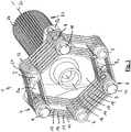
- FIG. 1 shows a torque transmission device 1 with a drive element not shown here, first clamping elements 2, 3, 4, which are evenly spaced in a circumferential direction of the torque transmission device 1, ie 120 ° apart.
- the torque transmission device 1 further has an output element 5, which in turn has three arms 5a, 5b, 5c, on each of which a second clamping element 6, 7, 8 is arranged projecting on one side.
- a first tensioning element 2, 3, 4 is thus arranged in each case between two second clamping elements 6, 7, 8, and vice versa.
- the total of six clamping elements form a uniform hexagon.
- FIG. 1 how out FIG. 1 can be seen, the clamping elements 2, 3, 4 and 6, 7, 8 in the form of rollers or bolts or bushings.
- the coupling elements 12-19 have the shape of oval rings or loops.
- the coupling elements thus each wrap around a partial circumference of approximately 180 ° of the clamping elements 4, 6 or 4, 8.
- the coupling elements can be wholly or at least partially made of glass fiber materials and accordingly also have a certain elasticity in the axial direction 20 of the torque transmission device 1. This means that the first clamping elements 2-4 can shift to some extent relative to the second clamping elements 6, 8, wherein the coupling elements 15-19 deform correspondingly.
- the torque transmission device 1 thus enables both a torque transmission in both directions of rotation.
- the coupling elements 15-19 enable a certain axial displacement of the drive element relative to the output element or vice versa, as well as a certain tilting movement of the drive element relative to the output element 5.
- FIG. 1 can be seen on the example of the first clamping element 2, paragraphs or discs 21, 22 are provided on the front sides of the clamping elements, in particular the Clearspannelements 2, which act as security elements and prevent the associated coupling elements of the sleeve or roller-like first Slip down clamping element 2.
- the clamping elements 2 - 4 or 6 - 8 may be made of hardened steel. As in FIG. 1 can be seen on the basis of the second clamping elements 6 - 8, the clamping elements may be cantilevered, ie be connected only at one of its two end faces with the drive element or the output element 5. In a torque transmission from the drive element to the output element or vice versa, it is therefore to some extent to a deformation or bending of the clamping elements 2-4 and 6-8, whereby a relatively uniform load distribution on the individual clamping elements and the connecting elements ensures them is.
- the pin-like end 23 of the output element 5 is mentioned, which is provided here with a serrated profile 24.
- the pin-like end can z. B. are inserted into a provided with an inner spline tread of a propeller shaft. The serration thus allows a Relatiwerschiebung the output element 5 relative to the propeller shaft.
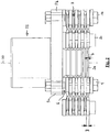
- FIG. 2 shows a plan view of the torque transmitting device of FIG. 1 , It can be clearly seen in this illustration that the coupling elements have a greater width in those sections which wrap around the clamping elements, seen in the direction of the axial direction 20, than in the "free" sections between the individual clamping elements.
- a coupling element 24 in the region of the clamping element 6 has a greater width B than in the region between the clamping element 6 and the clamping element 2, where the width of the coupling element 24 is only b. Due to the smaller width in the region between the adjacent clamping elements is achieved that the coupling elements can bend better and thus better axial relative displacements of the drive element relative to the output element or tilting movements of the drive element relative to the output element, and vice versa, allow.
- FIG. 3 shows an end view of the torque transmitting device 1 seen from the drive element not shown here on the output element 5.
- FIG. 4 shows a cross section through the torque transmission device 1 of FIG. 1 , It can be clearly seen that the clamping elements are sleeve-like clamping elements, which can be seen in particular on the clamping element 8.
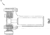
- FIG. 5 shows a further plan view of the torque transmitting device 1, in which case the different widths of the coupling elements in the region of the clamping elements on the one hand and in the region between the clamping elements on the other hand can be seen particularly clearly.
- FIG. 6 shows an embodiment of a coupling element.
- the coupling element shown in side view also has the shape of an oval ring or a loop.
- the coupling element 24 is the FIG. 6 However, not just, but executed in the region between the sections 24a, 24b, which wrap around in the assembled state associated clamping elements, curved.
- the curved central region 24c which by the way also has a smaller width than the "wrap-around sections 24a, 24b", thus enables an even better deformation of the coupling element 24 with an axial displacement or with a tilting of the drive element relative to the output element.
Landscapes
- Engineering & Computer Science (AREA)
- General Engineering & Computer Science (AREA)
- Mechanical Engineering (AREA)
- Motor Power Transmission Devices (AREA)
- Arrangement And Driving Of Transmission Devices (AREA)
Description
- Die vorliegende Erfindung betrifft ein Fahrzeug mit einer Drehmomentübertragungseinrichtung gemäß dem Oberbegriff des Patentanspruches 1.
- Ein derartiges Fahrzeug ist aus der
EP 1 818 556 A1 bekannt. - Bei Fahrzeugen mit Hinterradantrieb ist die Getriebeausgangswelle üblicherweise über eine Gelenkwelle und mehrere Gelenkwellengelenke mit dem Hinterachsgetriebe gekoppelt. Aus schwingungstechnischen Gründen weisen Gelenkwellen herkömmlicher Fahrzeuge in ihrem Mittelbereich üblicherweise ein Mittengelenk und ein Mittellager auf. Üblicherweise ist in diesem Bereich auch ein Verschiebefreiheitsgrad vorgesehen, wodurch in begrenztem Umfang ein Längenausgleich zwischen dem Getriebeausgang und dem Eingang des Hinterachsgetriebes ermöglicht wird.
- Eine konstruktive Vereinfachung wäre möglich, wenn es gelänge, anstatt einer "mehrteiligen Gelenkwelle" eine "einteilige Gelenkwelle" einzusetzen. Der "Längenausgleich" müsste dann an einem der beiden Enden der Gelenkwelle vorgesehen sein. Wünschenswert wäre es, wenn man eine "Verbindungseinrichtung" zur Kopplung einer Gelenkwelle mit einem Getriebeausgang bzw. mit einem Getriebeeingang zur Verfügung hätte, die nicht nur eine Drehmomentenübertragung ermöglicht, sondern darüber hinaus auch zumindest in begrenztem Umfang einen Verschiebefreiheitsgrad aufweist und Kippwinkel zwischen den miteinander zu koppelnden Elementen ausgleichen kann.
- Diese Aufgabe wird durch die Merkmale des Patentanspruches 1 gelöst. Vorteilhafte Ausgestaltungen und Weiterbildungen der Erfindung sind den Unteransprüchen zu entnehmen.
- Ausgangspunkt der Erfindung ist ein Fahrzeug mit einer "Drehmomentübertragungseinrichtung" zur Kopplung eines Antriebselements, insbesondere einer Getriebeausgangswelle eines Fahrzeugs, mit einem Abtriebselement, insbesondere einer Gelenkwelle. Die Drehmomentübertragungseinrichtung weist eine erste und eine zweite Gruppe von "Spannelementen" auf, welche die Form von Rollen, Bolzen bzw. Buchsen haben können. die Spannelemente der ersten Gruppe sind fest in Bezug auf das Antriebselement angeordnet und in einer Umfangsrichtung des Antriebselements gleichmäßig voneinander beabstandet.
- Die zweite Gruppe von Spannelementen sind fest in Bezug auf das Abtriebselement angeordnet und in einer Umfangsrichtung des Abtriebselements gleichmäßig voneinander beabstandet. Die Spannelemente sind so angeordnet, dass in Umfangsrichtung des An- bzw. Abtriebselements gesehen auf ein erstes Spannelement jeweils ein zweites Spannelement, und umgekehrt, folgt. Sind beispielsweise drei erste Spannelemente und drei zweite Spannelemente vorgesehen, so können die Spannelemente in Axialrichtung der Drehmomentübertragungseinrichtung gesehen an oder im Bereich der Eckpunkte eines gedachten, gleichmäßigen Sechsecks angeordnet sein.
- Um eine Drehmomentübertragung von den ersten Spannelementen auf die zweiten Spannelemente, bzw. umgekehrt zu ermöglichen, sind diese gemäß der Erfindung über "Kopplungselemente" gekoppelt. Jedes der ersten Spannelemente ist über mindestens ein Kopplungselement mit dem in der einen Umfangsrichtung nächsten zweiten Spannelement und über mindestens ein Kopplungselement mit dem in der entgegen gesetzten Umfangsrichtung nächsten zweiten Spannelement gekoppelt.
- Jedes der Kopplungselemente koppelt somit jeweils ein erstes Spannelement und ein in Umfangsrichtung dazu benachbartes zweites Spannelement miteinander.
- Die Kopplungselemente können die Form ovaler Ringe bzw. Schlingen aufweisen, welche jeweils ein Paar benachbarter Spannelemente teilweise umschlingen.
- Die Kopplungselemente können so beschaffen sein, dass sie ausschließlich Zugkräfte, nicht aber Druckkräfte übertragen können. Aufgrund der symmetrischen Anordnung der Kopplungselemente ist aber dennoch eine Drehmomentübertragung in beide Drehrichtungen möglich.
- Nach einer Weiterbildung der Erfindung sind die Kopplungselemente über die zugeordneten Spannelemente "gespannt". Die Kopplungselemente umschlingen dabei zumindest einen Teilumfang der Spannelemente.
- Für die Übertragung größerer Drehmomente kann vorgesehen sein, dass auf jedes der Spannelemente mehr als zwei Kopplungselemente, insbesondere eine Vielzahl von Kopplungselementen aufgespannt sind.
- Die ersten Spannelemente können mit den zweiten Spannelementen ausschließlich über die Kopplungselemente gekoppelt sein. Alternativ dazu ist es aber auch möglich, dass die Kopplungselemente und/oder die ersten und/oder die zweiten Spannelemente mit einem Kunststoffmaterial oder Gummi umschäumt bzw. eingegossen sind, ähnlich wie dies bei so genannten "Hardy-Scheiben" der Fall ist. An einem oder an beiden stirnseitigen Endbereichen der Spannelemente kann jeweils ein Absatz, ein Bund, eine Scheibe oder eine sonstige Sicherungseinrichtung vorgesehen sein, der bzw. die ein Herunterrutschen der Kopplungselemente von dem betreffenden Spannelement verhindert.
- Untersuchungen haben gezeigt, dass mit Kopplungselementen, die ganz oder zumindest teilweise aus Kunstfasen wie z. B. Carbonfasern oder Glasfasern bestehen, sehr große Kräfte und somit sehr große Drehmomente übertragen werden können. Aufgrund der Elastizität von Glasfasern ermöglichen Kopplungselemente aus Glasfasern auch eine gewisse Relativverschiebung des Antriebselements in Bezug auf das Abtriebselement in Axialrichtung.
- Zur Verringerung von Verschleißerscheinungen aufgrund von Relativbewegungen zwischen den Spannelementen und den daran anliegenden bzw. darüber gespannten Kopplungselementen können die Spannelemente aus einem Reibverschleiß mindernden Material hergestellt bzw. mit einem Reibverschleiß mindernden Material beschichtet sein. Hierfür in Frage kommen z.B. "Schmierstoffe wie Polytetraflurethylen, Graphit oder Titandioxid". Diese inkorporierten verschleißmindernden Stoffe bilden einen dünnen trennenden Schmierfilm zwischen den Spannelementen und den Kopplungselementen.
- Die Spannelemente können aus gehärtetem Stahl hergestellt sein. Die Spannelemente können fliegend gelagert sein, d. h. lediglich an einer ihrer Stirnseiten mit dem Antriebselement bzw. dem zugeordneten Abtriebselement verbunden sein. Bei einer fliegenden Lagerung werden die Spannelemente einer Drehmomentübertragung auf Biegung beansprucht und müssen dementsprechend ausgelegt sein.
- Im Folgenden wird die Erfindung im Zusammenhang mit der Zeichnung näher erläutert. Es zeigen:
- Figur 1
- eine Drehmomentübertragungseinrichtung gemäß der Erfindung in perspektivischer Darstellung;
- Figur 2
- eine Draufsicht auf die Drehmomentübertragungseinrichtung der
Figur 1 ; - Figur 3
- eine Stirnansicht der Drehmomentübertragungseinrichtung der
Figur 1 von der Antriebsseite her gesehen; - Figur 4
- einen Querschnitt durch die Drehmomentübertragungseinrichtung der
Figur 1 in perspektivischer Darstellung; - Figur 5
- eine weitere Draufsicht auf die Drehmomentübertragungseinrichtung der
Figur 1 ; und - Figur 6
- ein speziell geformtes Kopplungselement.
-
Figur 1 zeigt eine Drehmomentübertragungseinrichtung 1 mit einem hier nicht näher dargestellten Antriebselement, ersten Spannelementen 2, 3, 4, die in einer Umfangsrichtung der Drehmomentübertragungseinrichtung 1 gleichmäßig, d. h. 120° voneinander beabstandet sind. Die Drehmomentübertragungseinrichtung 1 weist ferner ein Abtriebselement 5 auf, das wiederum drei Arme 5a, 5b, 5c aufweist, an denen jeweils ein zweites Spannelement 6, 7, 8 einseitig abstehend angeordnet ist. Ein erstes Spannelement 2, 3, 4 ist somit jeweils zwischen zwei zweiten Spannelementen 6, 7, 8 angeordnet, und umgekehrt. Die insgesamt sechs Spannelemente bilden ein gleichmäßiges Sechseck. - Die zweiten Spannelemente 6, 7, 8 sind mittels Schrauben 9, 10, 11 an die Arme 5a, 5b, 5c des Abtriebselements 5 angeschraubt. Die Schrauben 9, 10, 11 durchsetzen dabei die zweiten Spannelemente 6, 7, 8.
- Wie aus
Figur 1 ersichtlich ist, haben die Spannelemente 2, 3, 4 sowie 6, 7, 8 die Form von Rollen bzw. Bolzen bzw. Buchsen. - Um eine Drehmomentübertragung von den mit dem hier nicht näher dargestellten Antriebselement verbundenen ersten Spannelementen 2, 3, 4 auf die mit dem Abtriebselement 5 verbundenen zweiten Spannelementen 6, 7, 8, und umgekehrt, zu ermöglichen, ist jedes der Spannelemente 2, 3, 4, 6, 7, 8 mit jeweils zwei in Umfangsrichtung benachbarten Spannelementen über mehrere Kopplungselemente verbunden. Beispielsweise ist das erste Spannelement 4 über vier Kopplungselemente 12, 13, 14, 15 mit dem zweiten Spannelement 6 und über ebenfalls vier weitere Kopplungselemente 16, 17, 18, 19 mit dem zweiten Spannelemente 8 verbunden.
- Wie aus
Figur 1 ersichtlich ist, haben die Kopplungselemente 12 - 19 die Form ovaler Ringe bzw. Schlingen. Die Kopplungselemente umschlingen somit jeweils einen Teilumfang von circa 180° der Spannelemente 4, 6 bzw. 4, 8. Die Kopplungselemente können ganz oder zumindest teilweise aus Glasfasermaterialen hergestellt sein und weisen dementsprechend auch eine gewisse Elastizität in Axialrichtung 20 der Drehmomentübertragungseinrichtung 1 auf. Dies bedeutet, die ersten Spannelemente 2 - 4 können sich in gewissem Umfang relativ zu den zweiten Spannelementen 6, 8 verschieben, wobei sich die Kopplungselemente 15 - 19 dementsprechend deformieren. - Die Drehmomentübertragungseinrichtung 1 ermöglicht somit sowohl eine Drehmomentübertragung in beide Drehrichtungen. Zusätzlich ermöglichen die Kopplungselemente 15 - 19 aber auch eine gewisse Axialverschiebung des Antriebselements gegenüber dem Abtriebselement bzw. umgekehrt sowie eine gewisse Kippbewegung des Antriebselements gegenüber dem Abtriebselement 5.
- Wie aus
Figur 1 am Bespiel des ersten Spannelements 2 ersichtlich ist, sind an den Stirnseiten der Spannelemente, hier insbesondere des Erstspannelements 2, Absätze bzw. Scheiben 21, 22 vorgesehen, die als Sicherungselemente fungieren und verhindern, dass die zugeordneten Kopplungselemente von dem buchsen- bzw. rollenartigen ersten Spannelement 2 herunterrutschen. - Die Spannelemente 2 - 4 bzw. 6 - 8 können aus gehärtetem Stahl hergestellt sein. Wie in
Figur 1 anhand der zweiten Spannelemente 6 - 8 ersichtlich ist, können die Spannelemente fliegend gelagert sein, d. h. nur an einer ihrer beiden Stirnseiten mit dem Antriebselement bzw. dem Abtriebselement 5 verbunden sein. Bei einer Drehmomentübertragung von dem Antriebselement auf das Abtriebselement bzw. umgekehrt kommt es daher in gewissen Umfang zu einer Deformierung bzw. Biegung der Spannelemente 2 - 4 bzw. 6 - 8, wodurch eine relativ gleichmäßige Lastverteilung auf die einzelnen Spannelemente und die sie verbindenden Kopplungselemente gewährleistet ist. - Vollständigkeitshalber sei noch das zapfenartige Ende 23 des Abtriebselements 5 erwähnt, das hier mit einem Kerbzahnprofil 24 versehen ist. Das zapfenartige Ende kann z. B. in ein mit einem Innenkerbzahnprofil versehenes Endstück einer Gelenkwelle eingeschoben werden. Die Kerbverzahnung ermöglicht somit eine Relatiwerschiebung des Abtriebselements 5 gegenüber der Gelenkwelle.
-
Figur 2 zeigt eine Draufsicht auf die Drehmomentübertragungseinrichtung derFigur 1 . In dieser Darstellung deutlich erkennbar ist, dass die Kopplungselemente in denjenigen Abschnitten, welche die Spannelemente umschlingen, in Richtung der Axialrichtung 20 gesehen eine größere Breite aufweisen als in den "freien" Abschnitten zwischen den einzelnen Spannelementen. Konkret weist beispielsweise ein Kopplungselement 24 im Bereich des Spannelements 6 eine größere Breite B auf als im Bereich zwischen dem Spannelement 6 und dem Spannelement 2, wo die Breite des Kopplungselements 24 lediglich b beträgt. Durch die geringere Breite im Bereich zwischen den benachbarten Spannelementen wird erreicht, dass sich die Kopplungselemente besser biegen können und somit besser axiale Relativverschiebungen des Antriebselements gegenüber dem Abtriebselement bzw. Kippbewegungen des Antriebselements gegenüber dem Abtriebselement, und umgekehrt, ermöglichen. -
Figur 3 zeigt eine Stirnansicht der Drehmomentübertragungseinrichtung 1 von dem hier nicht näher dargestellten Antriebselement her auf das Abtriebselement 5 gesehen. -
Figur 4 zeigt einen Querschnitt durch die Drehmomentübertragungseinrichtung 1 derFigur 1 . Deutlich zu erkennen ist, dass es sich bei den Spannelementen um buchsenartige Spannelemente handelt, was insbesondere an dem Spannelement 8 zu sehen ist. -
Figur 5 zeigt eine weitere Draufsicht auf die Drehmomentübertragungseinrichtung 1, wobei hier besonders deutlich die unterschiedlichen Breiten der Kopplungselemente im Bereich der Spannelemente einerseits und im Bereich zwischen den Spannelementen andererseits zu sehen sind. -
Figur 6 zeigt ein Ausführungsbeispiel eines Kopplungselements. Das inFigur 6 in Seitenansicht gezeigte Kopplungselement weist ebenfalls die Form eines ovalen Rings bzw. einer Schleife auf. Im Unterschied zu den Kopplungselementen, die im Zusammenhang mit denFiguren 1 - 5 beschrieben sind, ist das Kopplungselement 24 derFigur 6 jedoch nicht eben, sondern im Bereich zwischen den Abschnitten 24a, 24b, welche im montiertem Zustand zugeordnete Spannelemente umschlingen, gekrümmt ausgeführt. Der gekrümmte Mittelbereich 24c, der im Übrigen auch noch eine geringere Breite aufweist als die "Umschlingungsabschnitte 24a, 24b" ermöglicht somit bei einer Axialverschiebung bzw. bei einer Kippung des Antriebselements relativ zu dem Abtriebselement eine noch bessere Deformierung des Kopplungselements 24.
Claims (10)
- Fahrzeug mit einer Drehmomentübertragungseinrichtung (1) zur Kopplung einer Getriebeausgangswelle des Fahrzeugs mit einer Gelenkwelle (5) des Fahrzeugs, mit- einer ersten Gruppe von Spannelementen (2 - 4), die fest in Bezug auf die Getriebeausgangswelle angeordnet sind und die in einer Umfangsrichtung der Getriebeausgangswelle gleichmäßig voneinander beabstandet sind,- einer zweiten Gruppe von Spannelementen (6, 7, 8), die fest in Bezug auf die Gelenkwelle (5) angeordnet sind und die in einer Umfangsrichtung der Gelenkwelle (5) gleichmäßig voneinander beabstandet sind, wobei in Umfangsrichtung der Getriebeausgangswelle bzw. der Gelenkwelle gesehen auf ein erstes Spannelement jeweils ein zweites Spannelement, und umgekehrt folgt, und- Kopplungselementen (15 - 19, 24), wobei jedes der ersten Spannelemente (2 - 4) über mindestens ein Kopplungselement (15 - 19) mit dem in der einen Umfangsrichtung nächsten zweiten Spannelement (6 - 8) und über mindestens ein Kopplungselement (15 - 19) mit dem in der entgegen gesetzten Umfangsrichtung nächsten zweiten Spannelement (6 - 8) gekoppelt ist, und wobei die Kopplungselemente (12 - 19) über zugeordnete Spannelemente (2 - 4, 6 - 8) gespannt sind und die Kopplungselemente (12 - 19) die Spannelemente (2 - 4, 6 - 8) zumindest über einen Teilumfang der Spannelemente (2 - 4, 6 - 8) umschlingen, wobei- die Kopplungselemente aus einem Kunststoffmaterial bestehen, das durch Fasern verstärkt ist,dadurch gekennzeichnet, dass
die Spannelemente (2 - 4, 6 - 8) aus einem Material hergestellt sind, das einen als Schmierstoff wirkenden Stoff enthält oder die Spannelemente (2 - 4, 6 - 8) mit einem Material beschichtet sind, das einen als Schmierstoff wirkenden Stoff enthält, wobei es sich bei dem Schmierstoff um Polytetraflurethylen, Graphit oder um Titandioxid handelt. - Fahrzeug nach Anspruch 1, dadurch gekennzeichnet, dass jedes der Kopplungselemente (15 - 19) ein erstes Spannelement (2 - 4) und ein in Umfangsrichtung dazu benachbartes zweites Spannelement miteinander koppelt.
- Fahrzeug nach Anspruch 1 oder 2, dadurch gekennzeichnet, dass auf jedes der Spannelemente (2 - 4, 6 - 8) mehr als zwei Kopplungselemente (12 - 19), insbesondere eine Vielzahl von Kopplungselementen (12 - 19), aufgespannt sind.
- Fahrzeug nach einem der Ansprüche 1 bis 3, dadurch gekennzeichnet, dass die erste Gruppe von Spannelementen (2 - 4) mit der zweiten Gruppe von Spannelementen (6 - 8) ausschließlich über die Kopplungselemente (12 - 19) gekoppelt sind.
- Fahrzeug nach einem der Ansprüche 1 bis 4, dadurch gekennzeichnet, dass die Kopplungselemente (12 - 19) in ein elastisches, die einzelnen Kopplungselemente verbindendes Kopplungselement eingeschäumt bzw. eingegossen sind.
- Fahrzeug nach einem der Ansprüche 1 bis 5, dadurch gekennzeichnet, dass im stirnseitigen Endbereich der Spannelemente (2 - 4, 6 - 8) jeweils ein Absatz oder eine Scheibe (21, 22) vorgesehen ist, welcher bzw. welche ein Herunterrutschen der Kopplungselemente von dem betreffenden Spannelement (2 - 4, 6 - 8) verhindert bzw. verhindern.
- Fahrzeug nach einem der Ansprüche 1 bis 6, dadurch gekennzeichnet, dass die Kopplungselemente (12 - 19) zumindest teilweise aus Glasfasern bestehen.
- Fahrzeug nach Anspruch 7, dadurch gekennzeichnet, dass die Kopplungselemente aus einem Kunststoffmaterial bestehen, das durch Glasfasern, verstärkt ist.
- Fahrzeug nach einem der Ansprüche 1 bis 8, dadurch gekennzeichnet, dass die Kopplungselemente die Form ovaler Ringe bzw. Schlingen aufweisen.
- Fahrzeug nach einem der Ansprüche 1 bis 9, dadurch gekennzeichnet, dass die Spannelemente eine rollen-, bolzen bzw. buchsenartige Form aufweisen.
Applications Claiming Priority (1)
| Application Number | Priority Date | Filing Date | Title |
|---|---|---|---|
| DE200810034214 DE102008034214A1 (de) | 2008-07-23 | 2008-07-23 | Drehmomentübertragungseinrichtung |
Publications (2)
| Publication Number | Publication Date |
|---|---|
| EP2148106A1 EP2148106A1 (de) | 2010-01-27 |
| EP2148106B1 true EP2148106B1 (de) | 2017-03-01 |
Family
ID=41228281
Family Applications (1)
| Application Number | Title | Priority Date | Filing Date |
|---|---|---|---|
| EP09008019.3A Active EP2148106B1 (de) | 2008-07-23 | 2009-06-19 | Drehmomentübertragungseinrichtung |
Country Status (2)
| Country | Link |
|---|---|
| EP (1) | EP2148106B1 (de) |
| DE (1) | DE102008034214A1 (de) |
Families Citing this family (5)
| Publication number | Priority date | Publication date | Assignee | Title |
|---|---|---|---|---|
| DE102009009683A1 (de) | 2009-02-19 | 2010-08-26 | Bayerische Motoren Werke Aktiengesellschaft | Drehmomentübertragungseinrichtung insbesondere für Automobile und Motorräder |
| DE102009038039A1 (de) * | 2009-08-19 | 2011-02-24 | Bayerische Motoren Werke Aktiengesellschaft | Drehmomentübertragungseinrichtung |
| CN103032478A (zh) * | 2013-01-21 | 2013-04-10 | 吴实渊 | 一种空间柔性联轴器 |
| DE102014114460A1 (de) | 2014-10-06 | 2016-04-07 | xperion components GmbH & Co. KG | Anordnung für eine Wellenkupplung |
| DE102016221754A1 (de) * | 2016-11-07 | 2018-05-09 | Zf Friedrichshafen Ag | Lasche mit Koppelelement für eine elastische Kupplung |
Citations (1)
| Publication number | Priority date | Publication date | Assignee | Title |
|---|---|---|---|---|
| US6203434B1 (en) * | 1997-05-17 | 2001-03-20 | Daimlerchrysler Ag | Cardan-type joint including supportive compression bars |
Family Cites Families (13)
| Publication number | Priority date | Publication date | Assignee | Title |
|---|---|---|---|---|
| DE182230C (de) | ||||
| US1466238A (en) | 1920-04-22 | 1923-08-28 | Snead & Co Iron Works | Flexible joint |
| GB321999A (en) * | 1928-08-29 | 1929-11-28 | Christian Hamilton Gray | Improvements in or relating to universal joints |
| JPH0752427Y2 (ja) * | 1986-11-07 | 1995-11-29 | 東洋ゴム工業株式会社 | 高負荷トルク伝達用弾性継手 |
| US5033988A (en) * | 1989-03-07 | 1991-07-23 | Lord Corporation | Reversible endless belt rotary coupling |
| US5163876A (en) | 1990-07-30 | 1992-11-17 | Kop-Flex, Inc. | Method of constructing a composite flexible coupling element |
| DE4304274C1 (de) * | 1993-02-12 | 1994-03-17 | Sgf Gmbh & Co Kg | Gelenkscheibe, insbesondere für den Antriebsstrang in Kraftfahrzeugen |
| DE4437989C2 (de) | 1994-10-24 | 1996-11-14 | Sgf Gmbh & Co Kg | Verfahren zum Herstellen von Gelenkscheiben |
| DE19934469C2 (de) | 1999-07-27 | 2003-08-07 | Atec Weiss Gmbh & Co Kg | Flexible Wellenkupplung mit durch gummielastischem Material verbundenen, zueinander axial beabstandeten Lamellen |
| US6899629B2 (en) * | 2000-12-20 | 2005-05-31 | Nok-Vibracoustic Co., Ltd | Elastic coupler |
| JP3680780B2 (ja) * | 2001-10-11 | 2005-08-10 | 東洋ゴム工業株式会社 | 弾性継手 |
| US20070057480A1 (en) | 2003-05-09 | 2007-03-15 | Koyo Seiko Co., Ltd. | Eccentric thrust bearing assembly and a wheel with built-in suspension using the same |
| DE502006001490D1 (de) | 2006-02-10 | 2008-10-16 | Wulf Gaertner Autoparts Ag | Verfahren zur Herstellung einer Schlingeneinheit |
-
2008
- 2008-07-23 DE DE200810034214 patent/DE102008034214A1/de not_active Ceased
-
2009
- 2009-06-19 EP EP09008019.3A patent/EP2148106B1/de active Active
Patent Citations (1)
| Publication number | Priority date | Publication date | Assignee | Title |
|---|---|---|---|---|
| US6203434B1 (en) * | 1997-05-17 | 2001-03-20 | Daimlerchrysler Ag | Cardan-type joint including supportive compression bars |
Also Published As
| Publication number | Publication date |
|---|---|
| EP2148106A1 (de) | 2010-01-27 |
| DE102008034214A1 (de) | 2010-01-28 |
Similar Documents
| Publication | Publication Date | Title |
|---|---|---|
| DE102009020906B4 (de) | Verbindungsvorrichtung | |
| EP2406513B1 (de) | Schwingungsdämpfer für einen antriebsstrang | |
| EP2148106B1 (de) | Drehmomentübertragungseinrichtung | |
| EP1819939B1 (de) | Laschenkette für insbesondere einen fahrzeugantrieb | |
| DE3132877A1 (de) | Kupplung | |
| EP1818556B1 (de) | Verfahren zur Herstellung einer Schlingeneinheit | |
| DE60206553T2 (de) | CVT-Kettenriemen mit an Kettenlaschen auf oder zwischen Bolzenenden angebrachten Verschleisskissen | |
| DE2708538C3 (de) | Verbindung zwischen den Kettengliedern einer Gleiskette | |
| DE3514124A1 (de) | Kardanische doppelkupplung | |
| EP0878633A2 (de) | Wellengelenk | |
| EP1691095B1 (de) | Axiale Isolierung für ein kardanisches Kreuzgelenk | |
| EP1934502A1 (de) | Kettenlasche, diese beinhaltende kette, sowie damit gebildeter kettentrieb und damit ausgerüstetes fahrzeug | |
| EP1001182B1 (de) | Kreuzgelenkanordnung für den Einsatz in Gelenkwellen | |
| DE102009009683A1 (de) | Drehmomentübertragungseinrichtung insbesondere für Automobile und Motorräder | |
| EP1019642B1 (de) | Gelenkanordnung zur übertragung von drehmomentgeeigneten gelenkwellen | |
| EP2467609B1 (de) | Drehmomentuebertragungseinrichtung | |
| EP3320225B1 (de) | Gurt oder gurtsegment | |
| EP1382870B1 (de) | Elastische Kupplung | |
| EP3274604B1 (de) | Elastische ausgleichskupplung mit formschlüssig ineinandergreifenden naben | |
| WO2006058528A1 (de) | Laschenkette für insbesondere einen fahrzeugantrieb | |
| EP0534899A1 (de) | Antrieb für einen Radsatz eines Schienentriebfahrzeuges und Federelement für einen derartigen Antrieb | |
| DE102018106131A1 (de) | Umschlingungsmittel und CVT-Getriebe mit selbigem | |
| EP1691099B1 (de) | Axiale Isolierung für ein kardanisches Kreuzgelenk | |
| EP2163776B1 (de) | Gelenkwelle für Fahrzeuge | |
| EP1530685B1 (de) | Anschlusselement zur verbindung von gelenkspindeln mit anschlussaggregaten, insbesondere trefferhalterung mit konischer zentrierung |
Legal Events
| Date | Code | Title | Description |
|---|---|---|---|
| PUAI | Public reference made under article 153(3) epc to a published international application that has entered the european phase |
Free format text: ORIGINAL CODE: 0009012 |
|
| AK | Designated contracting states |
Kind code of ref document: A1 Designated state(s): AT BE BG CH CY CZ DE DK EE ES FI FR GB GR HR HU IE IS IT LI LT LU LV MC MK MT NL NO PL PT RO SE SI SK TR |
|
| AX | Request for extension of the european patent |
Extension state: AL BA RS |
|
| 17P | Request for examination filed |
Effective date: 20100211 |
|
| 17Q | First examination report despatched |
Effective date: 20100310 |
|
| RIN1 | Information on inventor provided before grant (corrected) |
Inventor name: FRANKE, OLIVER Inventor name: KORNPROBST, WOLFGANG Inventor name: TICHELMANN, PATRICK Inventor name: SCHUERMANN, HELMUT Inventor name: DULLENKOPF, DIRK Inventor name: HAHN, WOLFGANG |
|
| GRAP | Despatch of communication of intention to grant a patent |
Free format text: ORIGINAL CODE: EPIDOSNIGR1 |
|
| INTG | Intention to grant announced |
Effective date: 20160929 |
|
| GRAS | Grant fee paid |
Free format text: ORIGINAL CODE: EPIDOSNIGR3 |
|
| GRAA | (expected) grant |
Free format text: ORIGINAL CODE: 0009210 |
|
| AK | Designated contracting states |
Kind code of ref document: B1 Designated state(s): AT BE BG CH CY CZ DE DK EE ES FI FR GB GR HR HU IE IS IT LI LT LU LV MC MK MT NL NO PL PT RO SE SI SK TR |
|
| REG | Reference to a national code |
Ref country code: GB Ref legal event code: FG4D Free format text: NOT ENGLISH |
|
| RIN1 | Information on inventor provided before grant (corrected) |
Inventor name: TICHELMANN, PATRICK Inventor name: KORNPROBST, WOLFGANG Inventor name: SCHUERMANN, HELMUT Inventor name: DULLENKOPF, DIRK Inventor name: FRANKE, OLIVER Inventor name: HAHN, WOLFGANG |
|
| REG | Reference to a national code |
Ref country code: CH Ref legal event code: EP Ref country code: AT Ref legal event code: REF Ref document number: 871747 Country of ref document: AT Kind code of ref document: T Effective date: 20170315 |
|
| REG | Reference to a national code |
Ref country code: IE Ref legal event code: FG4D Free format text: LANGUAGE OF EP DOCUMENT: GERMAN |
|
| REG | Reference to a national code |
Ref country code: DE Ref legal event code: R096 Ref document number: 502009013684 Country of ref document: DE |
|
| REG | Reference to a national code |
Ref country code: FR Ref legal event code: PLFP Year of fee payment: 9 |
|
| REG | Reference to a national code |
Ref country code: NL Ref legal event code: MP Effective date: 20170301 |
|
| REG | Reference to a national code |
Ref country code: LT Ref legal event code: MG4D |
|
| PG25 | Lapsed in a contracting state [announced via postgrant information from national office to epo] |
Ref country code: LT Free format text: LAPSE BECAUSE OF FAILURE TO SUBMIT A TRANSLATION OF THE DESCRIPTION OR TO PAY THE FEE WITHIN THE PRESCRIBED TIME-LIMIT Effective date: 20170301 Ref country code: NO Free format text: LAPSE BECAUSE OF FAILURE TO SUBMIT A TRANSLATION OF THE DESCRIPTION OR TO PAY THE FEE WITHIN THE PRESCRIBED TIME-LIMIT Effective date: 20170601 Ref country code: GR Free format text: LAPSE BECAUSE OF FAILURE TO SUBMIT A TRANSLATION OF THE DESCRIPTION OR TO PAY THE FEE WITHIN THE PRESCRIBED TIME-LIMIT Effective date: 20170602 Ref country code: FI Free format text: LAPSE BECAUSE OF FAILURE TO SUBMIT A TRANSLATION OF THE DESCRIPTION OR TO PAY THE FEE WITHIN THE PRESCRIBED TIME-LIMIT Effective date: 20170301 Ref country code: HR Free format text: LAPSE BECAUSE OF FAILURE TO SUBMIT A TRANSLATION OF THE DESCRIPTION OR TO PAY THE FEE WITHIN THE PRESCRIBED TIME-LIMIT Effective date: 20170301 |
|
| PG25 | Lapsed in a contracting state [announced via postgrant information from national office to epo] |
Ref country code: LV Free format text: LAPSE BECAUSE OF FAILURE TO SUBMIT A TRANSLATION OF THE DESCRIPTION OR TO PAY THE FEE WITHIN THE PRESCRIBED TIME-LIMIT Effective date: 20170301 Ref country code: ES Free format text: LAPSE BECAUSE OF FAILURE TO SUBMIT A TRANSLATION OF THE DESCRIPTION OR TO PAY THE FEE WITHIN THE PRESCRIBED TIME-LIMIT Effective date: 20170301 Ref country code: BG Free format text: LAPSE BECAUSE OF FAILURE TO SUBMIT A TRANSLATION OF THE DESCRIPTION OR TO PAY THE FEE WITHIN THE PRESCRIBED TIME-LIMIT Effective date: 20170601 Ref country code: SE Free format text: LAPSE BECAUSE OF FAILURE TO SUBMIT A TRANSLATION OF THE DESCRIPTION OR TO PAY THE FEE WITHIN THE PRESCRIBED TIME-LIMIT Effective date: 20170301 |
|
| PG25 | Lapsed in a contracting state [announced via postgrant information from national office to epo] |
Ref country code: NL Free format text: LAPSE BECAUSE OF FAILURE TO SUBMIT A TRANSLATION OF THE DESCRIPTION OR TO PAY THE FEE WITHIN THE PRESCRIBED TIME-LIMIT Effective date: 20170301 |
|
| PG25 | Lapsed in a contracting state [announced via postgrant information from national office to epo] |
Ref country code: CZ Free format text: LAPSE BECAUSE OF FAILURE TO SUBMIT A TRANSLATION OF THE DESCRIPTION OR TO PAY THE FEE WITHIN THE PRESCRIBED TIME-LIMIT Effective date: 20170301 Ref country code: SK Free format text: LAPSE BECAUSE OF FAILURE TO SUBMIT A TRANSLATION OF THE DESCRIPTION OR TO PAY THE FEE WITHIN THE PRESCRIBED TIME-LIMIT Effective date: 20170301 Ref country code: RO Free format text: LAPSE BECAUSE OF FAILURE TO SUBMIT A TRANSLATION OF THE DESCRIPTION OR TO PAY THE FEE WITHIN THE PRESCRIBED TIME-LIMIT Effective date: 20170301 Ref country code: EE Free format text: LAPSE BECAUSE OF FAILURE TO SUBMIT A TRANSLATION OF THE DESCRIPTION OR TO PAY THE FEE WITHIN THE PRESCRIBED TIME-LIMIT Effective date: 20170301 |
|
| PG25 | Lapsed in a contracting state [announced via postgrant information from national office to epo] |
Ref country code: PT Free format text: LAPSE BECAUSE OF FAILURE TO SUBMIT A TRANSLATION OF THE DESCRIPTION OR TO PAY THE FEE WITHIN THE PRESCRIBED TIME-LIMIT Effective date: 20170703 Ref country code: IS Free format text: LAPSE BECAUSE OF FAILURE TO SUBMIT A TRANSLATION OF THE DESCRIPTION OR TO PAY THE FEE WITHIN THE PRESCRIBED TIME-LIMIT Effective date: 20170701 Ref country code: PL Free format text: LAPSE BECAUSE OF FAILURE TO SUBMIT A TRANSLATION OF THE DESCRIPTION OR TO PAY THE FEE WITHIN THE PRESCRIBED TIME-LIMIT Effective date: 20170301 |
|
| REG | Reference to a national code |
Ref country code: DE Ref legal event code: R097 Ref document number: 502009013684 Country of ref document: DE |
|
| PLBE | No opposition filed within time limit |
Free format text: ORIGINAL CODE: 0009261 |
|
| STAA | Information on the status of an ep patent application or granted ep patent |
Free format text: STATUS: NO OPPOSITION FILED WITHIN TIME LIMIT |
|
| PG25 | Lapsed in a contracting state [announced via postgrant information from national office to epo] |
Ref country code: DK Free format text: LAPSE BECAUSE OF FAILURE TO SUBMIT A TRANSLATION OF THE DESCRIPTION OR TO PAY THE FEE WITHIN THE PRESCRIBED TIME-LIMIT Effective date: 20170301 Ref country code: MC Free format text: LAPSE BECAUSE OF FAILURE TO SUBMIT A TRANSLATION OF THE DESCRIPTION OR TO PAY THE FEE WITHIN THE PRESCRIBED TIME-LIMIT Effective date: 20170301 |
|
| REG | Reference to a national code |
Ref country code: CH Ref legal event code: PL |
|
| 26N | No opposition filed |
Effective date: 20171204 |
|
| PG25 | Lapsed in a contracting state [announced via postgrant information from national office to epo] |
Ref country code: SI Free format text: LAPSE BECAUSE OF FAILURE TO SUBMIT A TRANSLATION OF THE DESCRIPTION OR TO PAY THE FEE WITHIN THE PRESCRIBED TIME-LIMIT Effective date: 20170301 |
|
| REG | Reference to a national code |
Ref country code: IE Ref legal event code: MM4A |
|
| PG25 | Lapsed in a contracting state [announced via postgrant information from national office to epo] |
Ref country code: LU Free format text: LAPSE BECAUSE OF NON-PAYMENT OF DUE FEES Effective date: 20170619 Ref country code: IE Free format text: LAPSE BECAUSE OF NON-PAYMENT OF DUE FEES Effective date: 20170619 Ref country code: LI Free format text: LAPSE BECAUSE OF NON-PAYMENT OF DUE FEES Effective date: 20170630 Ref country code: CH Free format text: LAPSE BECAUSE OF NON-PAYMENT OF DUE FEES Effective date: 20170630 |
|
| REG | Reference to a national code |
Ref country code: BE Ref legal event code: MM Effective date: 20170630 |
|
| REG | Reference to a national code |
Ref country code: FR Ref legal event code: PLFP Year of fee payment: 10 |
|
| REG | Reference to a national code |
Ref country code: AT Ref legal event code: MM01 Ref document number: 871747 Country of ref document: AT Kind code of ref document: T Effective date: 20170619 |
|
| PG25 | Lapsed in a contracting state [announced via postgrant information from national office to epo] |
Ref country code: BE Free format text: LAPSE BECAUSE OF NON-PAYMENT OF DUE FEES Effective date: 20170630 |
|
| PG25 | Lapsed in a contracting state [announced via postgrant information from national office to epo] |
Ref country code: MT Free format text: LAPSE BECAUSE OF FAILURE TO SUBMIT A TRANSLATION OF THE DESCRIPTION OR TO PAY THE FEE WITHIN THE PRESCRIBED TIME-LIMIT Effective date: 20170301 |
|
| PG25 | Lapsed in a contracting state [announced via postgrant information from national office to epo] |
Ref country code: AT Free format text: LAPSE BECAUSE OF NON-PAYMENT OF DUE FEES Effective date: 20170619 |
|
| PG25 | Lapsed in a contracting state [announced via postgrant information from national office to epo] |
Ref country code: HU Free format text: LAPSE BECAUSE OF FAILURE TO SUBMIT A TRANSLATION OF THE DESCRIPTION OR TO PAY THE FEE WITHIN THE PRESCRIBED TIME-LIMIT; INVALID AB INITIO Effective date: 20090619 |
|
| PG25 | Lapsed in a contracting state [announced via postgrant information from national office to epo] |
Ref country code: CY Free format text: LAPSE BECAUSE OF NON-PAYMENT OF DUE FEES Effective date: 20170301 |
|
| PG25 | Lapsed in a contracting state [announced via postgrant information from national office to epo] |
Ref country code: MK Free format text: LAPSE BECAUSE OF FAILURE TO SUBMIT A TRANSLATION OF THE DESCRIPTION OR TO PAY THE FEE WITHIN THE PRESCRIBED TIME-LIMIT Effective date: 20170301 |
|
| PG25 | Lapsed in a contracting state [announced via postgrant information from national office to epo] |
Ref country code: TR Free format text: LAPSE BECAUSE OF FAILURE TO SUBMIT A TRANSLATION OF THE DESCRIPTION OR TO PAY THE FEE WITHIN THE PRESCRIBED TIME-LIMIT Effective date: 20170301 |
|
| P01 | Opt-out of the competence of the unified patent court (upc) registered |
Effective date: 20230502 |
|
| PGFP | Annual fee paid to national office [announced via postgrant information from national office to epo] |
Ref country code: FR Payment date: 20230622 Year of fee payment: 15 Ref country code: DE Payment date: 20230620 Year of fee payment: 15 |
|
| PGFP | Annual fee paid to national office [announced via postgrant information from national office to epo] |
Ref country code: IT Payment date: 20230630 Year of fee payment: 15 Ref country code: GB Payment date: 20230622 Year of fee payment: 15 |