EP0877397A2 - Magnetblock für Einfügungsvorrichtung - Google Patents
Magnetblock für Einfügungsvorrichtung Download PDFInfo
- Publication number
- EP0877397A2 EP0877397A2 EP98400896A EP98400896A EP0877397A2 EP 0877397 A2 EP0877397 A2 EP 0877397A2 EP 98400896 A EP98400896 A EP 98400896A EP 98400896 A EP98400896 A EP 98400896A EP 0877397 A2 EP0877397 A2 EP 0877397A2
- Authority
- EP
- European Patent Office
- Prior art keywords
- magnet
- block
- base
- insert
- magnet block
- Prior art date
- Legal status (The legal status is an assumption and is not a legal conclusion. Google has not performed a legal analysis and makes no representation as to the accuracy of the status listed.)
- Withdrawn
Links
Images


Classifications
-
- H—ELECTRICITY
- H01—ELECTRIC ELEMENTS
- H01F—MAGNETS; INDUCTANCES; TRANSFORMERS; SELECTION OF MATERIALS FOR THEIR MAGNETIC PROPERTIES
- H01F7/00—Magnets
- H01F7/02—Permanent magnets [PM]
- H01F7/0273—Magnetic circuits with PM for magnetic field generation
- H01F7/0278—Magnetic circuits with PM for magnetic field generation for generating uniform fields, focusing, deflecting electrically charged particles
-
- H—ELECTRICITY
- H05—ELECTRIC TECHNIQUES NOT OTHERWISE PROVIDED FOR
- H05H—PLASMA TECHNIQUE; PRODUCTION OF ACCELERATED ELECTRICALLY-CHARGED PARTICLES OR OF NEUTRONS; PRODUCTION OR ACCELERATION OF NEUTRAL MOLECULAR OR ATOMIC BEAMS
- H05H7/00—Details of devices of the types covered by groups H05H9/00, H05H11/00, H05H13/00
- H05H7/04—Magnet systems, e.g. undulators, wigglers; Energisation thereof
-
- H—ELECTRICITY
- H01—ELECTRIC ELEMENTS
- H01F—MAGNETS; INDUCTANCES; TRANSFORMERS; SELECTION OF MATERIALS FOR THEIR MAGNETIC PROPERTIES
- H01F13/00—Apparatus or processes for magnetising or demagnetising
Definitions
- the present invention relates to a novel magnet block assembly for an insertion device which is inserted into the linear part of an electron accelerator or electronic storage ring to emit a synchrotron radiation of high intensity. More particularly, the invention relates to an assembly of permanent magnet blocks for a compact-size insertion device of a small period length having a large number of periods despite the compactness as well as to a method for the magnetization of the magnet blocks in the assembly.
- an insertion device is a device inserted into the linear part of an electron accelerator or electronic storage ring to emit a synchrotron radiation of high intensity.
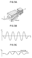
- An insertion device of the prior art is a device, as is illustrated in Figure 3A by a perspective view, having a structure of a magnet block assembly consisting of at least two arrays of permanent magnet blocks disposed to oppose each the other to form an air gap therebetween.
- Figure 3A When the directions of magnetization of the individual permanent magnet blocks are as shown in Figure 3A indicated by the small arrows on the end surfaces of the respective magnet blocks, as is illustrated in Figure 3B, a periodical magnetic field is generated in the air gap between the opposite arrays of the magnet blocks as indicated by the sine curve within the plane defined by the axes Z and Y in Figure 3A.
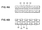
- the insertion device to generate such a periodical magnetic field are classified into two types including, one, those of the Halbach type composed of permanent magnet blocks 20, 30, 40, 50, ⁇ only as is schematically illustrated in Figure 4A by a side view and, the other, those of the hybrid type of which each array is composed of alternately arranged permanent magnet blocks 30, 50, ⁇ and blocks of a soft magnetic material or pole pieces 32, .
- the electron takes a meandering motion within the plane defined by the axes Z and X as is illustrated in Figure 3C to emit a synchrotron radiation at each of the meandering points as is reported by Halbach in Nuclear Instruments and Methods, volume 187, page 109 (1981).
- the mode for the emission of the synchrotron radiation is called either a wiggler mode or undulator mode depending on the extent of meandering of the electrons.
- the radiations emitted at the respective meandering points are superimposed to give a white synchrotron radiation having an overall intensity 10 to 1000 times higher than the radiation from a bending electromagnet.
- the radiations emitted from the respective meandering points interfere each with the others to give a radiation intensity 10 to 1000 times still higher than the wiggler mode radiations relative to the fundamental radiation and higher harmonics thereof.
- an undulator mode is obtained when the value of K is about 1 or smaller while the radiation is of the wiggler mode when K is otherwise.
- the terms of undulator and insertion device are used in the present invention to cover both of these two modes.
- the "air gap direction” means the direction from a magnet block in a first magnet block array to a magnet block in a second magnet block array to oppose the magnet block in the first array or, namely, the direction of the axis Y in Figure 3A.
- the "axial direction” in the following description means the direction of the orbit of electrons entering and traveling through the periodical magnetic field between the magnet block arrays or, namely, the direction of the axis Z in Figure 3A.
- insertion devices are grossly classified into those of the Halbach type and those of the hybrid type, no great differences are found therebetween relative to the value and distribution of the magnetic field. Generally speaking, however, the overall weight of the magnet blocks can be smaller in the hybrid type ones than in the Halbach type ones.
- the hybrid type insertion devices were preferred in the early stage of development when the manufacturing technology was at a low level not to give magnet blocks with high accuracy relative to the value and angle of magnetization in the magnet blocks while the requirements for the accuracy of the above were lower in the hybrid type than in the Halbach type.
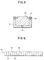
- the magnet block 20 is set in a rigid cassette 21 of a non-magnetic material and fixed at the position either by using an adhesive or by a mechanical means with presser plates 23 and screw bolts 24.
- the adhesive means and mechanical means can be used in combination. Basically, the mechanical means has higher reliability than adhesive bonding.
- the magnetic field generated by the magnet block can be adjusted by means of the adjustment hole 22 formed on the bottom or on the side wall of the cassette 21. Since the cassette 21 can be prepared by mechanical working using precision machine tools, the dimensional accuracy of the cassette 21 is generally high as compared with the magnet block 20.
- the positioning accuracy of the magnet blocks 20 in the length-wise direction of the magnet block array is particularly important, the positioning accuracy of the magnet blocks as required can be obtained when the accuracy in the dimension of the cassette 21 and the screwing females for the screw bolts 23 is ensured.
- the permanent magnet blocks 20 in the insertion devices are usually fixed and assembled by using a cassette 21 in most cases.
- the screw bolt 24 thrusted into the female in the cassette of 2.5 mm thickness cannot be larger than the screw bolt of the M1 size in consideration of the difficulty in tapping of the female thread and the size of the bolt head. Since the magnetic a-ttractive force between the oppositely facing two permanent magnet blocks in the two arrays is so strong that no very reliable assemblage of the magnet blocks can be ensured with so feeble holding means with tiny screw bolts 24.
- a magnet block assembly for a short-period insertion device in which, as is schematically illustrated in Figure 6, a plurality of magnet blocks are assembled in an array and magnetized with high precision in alternately reversed directions perpendicular to the length-wise direction of the array.
- the magnet block arrays there proposed serve to realize an insertion device of a period length not exceeding 20 mm.
- the characteristic advantages obtained with this magnet block assembly include a decrease in the requirement for the dimensional accuracy of the individual magnet blocks because a single permanent magnet block here covers a period or more in a conventional Halbach type insertion device composed of four or more magnet blocks, a decreased problem due to the working-degraded surface layer of the magnet blocks, applicability of the conventional assembling method with non-magnetic cassettes and a decrease in the assembling accuracy of the magnet blocks as a consequence of the decrease in the number of the magnet blocks.
- This method however, has different difficulties relating to the accuracy in the distribution of the magnetic field for the magnetization of the magnet blocks and precision control of the positions of magnetization.
- the present invention accordingly has an object to provide a novel assembly of permanent magnet blocks for an insertion device of a small period length not exceeding, for example, 10 mm, with which the above described difficulties and disadvantages in the prior art can be overcome by a simple and convenient means.
- the magnet block assembly for an insertion device is an assembly which comprises:
- Figures 1A and 1B are each a schematic length-wise cross sectional view of an elongated composite magnet block for an insertion device of the Halbach type and hybrid type, respectively, according to the invention.
- Figure 2 is a schematic illustration of the magnetization system for the magnetization of the composite magnet block for an insertion device according to the invention.
- Figure 3A is a schematic perspective view of the magnet block arrays of the Halbach type for a conventional insertion device.
- Figure 3B is a graph showing the sine-curved periodical magnetic field generated in the air gap between the magnet block arrays of Figure 3A.
- Figure 3C is an illustration of the meandering electron orbit travelling in the periodical magnetic field shown in Figure 3B.
- Figure 4A shows the basic arrangement of the permanent magnet block assemblies in an insertion device of the Halbach type.
- Figure 4B shows the basic arrangement of the permanent magnet blocks and soft-magnetic pole pieces in an insertion device of the hybrid type.
- Figure 5 is a cross sectional view of a permanent magnet block held in a non-magnetic cassette to build up a planar undulator.
- Figure 6 illustrates a magnetization pattern of permanent magnet blocks in an undulator of a small period length.
- the principle of the above defined magnet block assemblies of the invention for an insertion device is applicable to insertion devices of any size, the invention is particularly useful and advantageous when applied to an insertion device having a period length not exceeding, for example, 10 mm.
- Figures 1A and 1B each schematically illustrate a length-wise cross sectional view of a composite magnet block of the planar undulator 1A and 1B of an insertion device of the Halbach type and hybrid type, respectively.
- the base block of a permanent magnet 10A or 10B as a base of the composite magnet block 1A,1B must have a sufficient length corresponding to at least one period of the insertion device.
- the axis of easy magnetization thereof should be in the air gap direction or, namely, in the direction perpendicular to the travelling direction of electrons, i.e. the axial direction, in the air gap as indicated by the arrows written in the base magnet block 10A.
- the magnet block 10A is prepared by mechanical working on a magnet block by using a suitable machine tool with a grinding stone. Namely, a magnet block is mechanically worked to form a plurality of slits across the block, into which insert magnet pieces 3A, 5A, 7A, ⁇ are to be inserted each between two adjacent cantilevered sectional parts 2A, 4A, 6A, 8A, ⁇ , at regular intervals to define the period length of the undulator.
- Each of the slits formed across the base magnet block 10A has a thickness just to fit the insert magnet piece 3A, 5A, 7A, ⁇ to be inserted thereinto without any play and fixed thereto, for example, by using an adhesive to complete the composite magnet block 1A.
- the base magnet block 10A with a plurality of slits is magnetized in the cantilever sectional parts 2A, 4A, 6A, 8A, ⁇ in the alternately reversed air gap direction as shown by the arrows written in the respective parts while the insert magnet pieces 3A, 5A, 7A, ⁇ are magnetized in the alternately reversed axial direction also shown by the arrows written therein.
- the base magnet block 10A and the insert magnet pieces 3A,5A,7A, ⁇ can be magnetized separately in advance of the assemblage thereof into a composite magnet block 1A. It is an alternative possible way that these members before magnetization are assembled into the form of the composite magnet block 1A and the members are magnetized at one time by means of a pulsed magnetic field for magnetization.
- the two opposite cantilever sectional parts on the opposite composite magnet blocks 1A, 1A are magnetized in the same air gap direction while each of the insert magnet pieces in one of the composite magnet block is magnetized in the axial direction reverse to that of the insert magnet piece oppositely facing the piece in the other composite magnet block.
- Figure 1B is a schematic length-wise cross sectional view of a composite magnet block 1B for an insertion device of the hybrid type.
- the base magnet block 10B here is conformal to the base magnet block 10A illustrated in Figure 1A for the Halbach type with a plurality of slits across the base magnet block 10B, into each of which an insert pole piece of a soft magnetic material 3B, 5B, 7B, ⁇ is inserted, instead of the insert magnet pieces 3A, 5A, 7A, ⁇ in Figure 1A, each between the cantilever sectional parts 2B, 4B, 6B, 8B, ⁇ . It is preferable in this case that the cantilever sectional parts 2B, 4B, 6B, 8B, ⁇ are magnetized each in the alternately reversed axial direction.
- the elongated magnet block 10B is anisotropically magnetic, it is therefore preferable that the axis of easy magnetization thereof is in the axial direction.
- the direction of magnetization of each of the cantilever sectional parts is in the reversely axial direction relative to that of the oppositely facing cantilever sectional part in the other composite magnet block 1B.
- the composite magnet block 1A, 1B being composed on the base of a single base magnet block 10A, 10B instead of integration of a large number of unit magnet blocks in the prior art, with insertion of the insert magnet pieces or insert pole pieces inserted into the slits in the base magnet block, is advantageously free from the dimensional error in the axial direction due to superimposition of the thickness errors in the individual unit magnet blocks in the prior art.
- This advantage is of particular significance in an insertion device of which the period length is small to be, for example, 10 mm or less.
- Figure 2 is a schematic illustration of the system to generate a pulsed magnetic field for the magnetization of the composite magnet block 1A with a cross sectional view of the electromagnet 6 as the magnetization head.
- the electric charge accumulated in the capacitor bank 7 is instantaneously discharged by means of the thyristor switch 8 to cause a very large electric current through the coil 9 of the electromagnet 6 so that a pulse-wise large magnetic field indicated by the arrow B is generated to form a closed magnetic circuit along the route from the N1 pole to the S1 pole of the electromagnet 6 through the cantilever sectional part 4A, insert magnet piece 3A and cantilever sectional part 2A so that they are magnetized in the direction indicated by the respective arrows.
- the magnetic field for the magnetization in this case should be at least 15 kOe or, preferably, at least 18 kOe in order to accomplish magnetization with good reliability.
- the pulse width of the pulsed magnetic field should be at least 0.5 msecond or, preferably, at least 2 mseconds. It is of course possible to accomplish magnetization with a static magnetic field if an electromagnet and a DC power source of such a large capacity are available disregarding the large costs therefor.
- the magnetization is conducted after assemblage of the base magnet block 10A with slits and the insert magnet pieces 3A, 5A, 7A, ⁇ into the composite magnet block 1A, it is of course optional that the base magnet block 10A with slits and the insert magnet pieces 3A, 5A, 7A, ⁇ are separately magnetized in advance and the thus magnetized members are assembled into a magnetized composite magnet block 1A.
- the magnetic flux for magnetization forms a closed circuit from the N1 pole of the magnetization head 6 to the S1 pole thereof through the cantilever sectional part 4A, insert magnet piece 3A and cantilever sectional part 2A as indicated by the arrows B1, B2 and B3, respectively, so that the cantilever sectional parts 2A, 4A and the insert magnet piece 3A can be magnetized at one time to give a magnetized composite magnet block 1A in which the insert magnet pieces 3A, 5A, 7A, ⁇ can be spontaneously positioned by means of the repulsive or attractive force with the cantilever sectional parts 2A, 4A, 6A, 8A ⁇ .
- the types of the permanent magnets forming the composite magnet blocks 1A, 1B are not particularly limitative but anisotropically magnetizable magnets prepared by a powder metallurgical process from a rare earth metal-based alloy, such as the samarium-cobalt alloys and rare earth-iron-boron alloys, are preferred in respect of the strong magnetic field generated in the air gap between the composite magnet blocks.
- a rare earth metal-based alloy such as the samarium-cobalt alloys and rare earth-iron-boron alloys
- rare earth-iron-boron alloys are more preferable due to easiness in the magnetization with a pulsed magnetic field.
- the magnetized composite magnet blocks are held each in a holding cassette without problems.
- the material to form the holding cassette is not particularly limitative provided that the material is rigid and non-magnetic including aluminum or aluminum-based alloys, stainless steels and brass, of which stainless steels are preferred in respect of their high sliding resistance.
- the soft magnetic material for the insert pole pieces to be inserted into the slits in the base magnet block 10B for a hybrid type composite magnet block 1B is preferably iron or an iron-based alloy such as a low-carbon steel SS400, SUY and iron-cobalt alloys.
- Two or more of the composite magnet blocks 1A or 1B are assembled into an undulator of a small period length for an insertion device, in which the number N of periods in a composite magnet block of 100 cm length can be as large as 100 assuming a period length of 10 mm according to the invention. Since the theoretical intensity of radiation emitted from an insertion device is proportional to the square of the number N, a very strong synchrotron radiation can be emitted even in a compact-size accelerator ring provided with an insertion device according to the invention.
- insert magnet pieces each having dimensions of 40 mm by 15 mm by 2 mm, of which the axis of easy magnetization was in the direction of the 2 mm thickness, were prepared from the same rare earth magnet alloy. These insert magnet pieces were inserted into the slits in the base magnet blocks to be fitted thereto without play to give forty composite magnet blocks.
- a magnetization head was prepared which had magnetization teeth of a five-period span so as to enable magnetization of one of the above prepared composite magnet blocks at one time.
- the yoke of the electromagnet for the magnetization head was formed by laminating punch-formed 0.5 mm thick pure iron sheets and provided with a coil.
- the magnetization teeth of the magnetization head were brought into contact with the surface of the composite magnet block and magnetization thereof was conducted by energizing the coil with a capacitor bank of 4000 volts ⁇ 5000 ⁇ F capacity to generate a pulsed magnetic field of at least 20 kOe as the peak value.
- Each of the magnetized composite magnet blocks was inserted into a holding cassette made from a non-magnetic stainless steel SUS 316L and 20 a group of the cassettes were linearly assembled to form a 800 mm long elongated composite magnet block array in such a direction that each of the insert magnet pieces in all of the composite magnet blocks was within a plane across the array.
- a pair of the composite magnet block arrays were positioned to oppose each the other in such a way that each of the insert magnet pieces in one of the arrays just opposed an insert magnet piece in the other array with an air gap of 4 mm.
- Distribution of the periodical magnetic field in the air gap of the thus prepared 800 mm-long undulator of 100 periods was measured by using a small-area Hall sensor to find that the peak values of the peaks in the periodical magnetic field were very uniform with a variation of ⁇ 1.5% without undertaking any adjusting means.
Landscapes
- Physics & Mathematics (AREA)
- Engineering & Computer Science (AREA)
- Electromagnetism (AREA)
- Power Engineering (AREA)
- Optics & Photonics (AREA)
- Plasma & Fusion (AREA)
- Spectroscopy & Molecular Physics (AREA)
- Particle Accelerators (AREA)
Applications Claiming Priority (3)
| Application Number | Priority Date | Filing Date | Title |
|---|---|---|---|
| JP95542/97 | 1997-04-14 | ||
| JP9554297 | 1997-04-14 | ||
| JP09554297A JP3249930B2 (ja) | 1997-04-14 | 1997-04-14 | 挿入光源 |
Publications (2)
| Publication Number | Publication Date |
|---|---|
| EP0877397A2 true EP0877397A2 (de) | 1998-11-11 |
| EP0877397A3 EP0877397A3 (de) | 2000-11-08 |
Family
ID=14140462
Family Applications (1)
| Application Number | Title | Priority Date | Filing Date |
|---|---|---|---|
| EP98400896A Withdrawn EP0877397A3 (de) | 1997-04-14 | 1998-04-10 | Magnetblock für Einfügungsvorrichtung |
Country Status (5)
| Country | Link |
|---|---|
| US (1) | US6057656A (de) |
| EP (1) | EP0877397A3 (de) |
| JP (1) | JP3249930B2 (de) |
| KR (1) | KR100487082B1 (de) |
| CN (1) | CN1149594C (de) |
Cited By (4)
| Publication number | Priority date | Publication date | Assignee | Title |
|---|---|---|---|---|
| DE19953650A1 (de) * | 1999-11-08 | 2001-05-23 | Inst Mikrotechnik Mainz Gmbh | Verfahren zur Herstellung und Magazinierung von Einzelmagnetbauteilen sowie deren Montage zur Herstellung von miniatursisierten Magnetsystemen und solche Magnetsysteme |
| RU2718537C1 (ru) * | 2019-12-04 | 2020-04-08 | Андрей Борисович Захаренко | Способ намагничивания и сборки кольца Хальбаха ротора электромашины (варианты) |
| EP3633698A4 (de) * | 2017-05-26 | 2021-02-24 | Nitto Denko Corporation | Magnetherstellungsverfahren und magnetmagnetisierungsverfahren |
| US20220384083A1 (en) * | 2021-05-28 | 2022-12-01 | Toyota Jidosha Kabushiki Kaisha | Method for manufacturing halbach magnet array |
Families Citing this family (17)
| Publication number | Priority date | Publication date | Assignee | Title |
|---|---|---|---|---|
| JP4021982B2 (ja) * | 1998-03-03 | 2007-12-12 | 信越化学工業株式会社 | ハイブリッド型ウイグラ |
| US6545436B1 (en) * | 1999-11-24 | 2003-04-08 | Adelphi Technology, Inc. | Magnetic containment system for the production of radiation from high energy electrons using solid targets |
| JP2006222131A (ja) * | 2005-02-08 | 2006-08-24 | Neomax Co Ltd | 永久磁石体 |
| US7956557B1 (en) | 2007-09-11 | 2011-06-07 | Advanced Design Consulting Usa, Inc. | Support structures for planar insertion devices |
| US20140211360A1 (en) * | 2009-06-02 | 2014-07-31 | Correlated Magnetics Research, Llc | System and method for producing magnetic structures |
| CN102110523B (zh) * | 2010-12-22 | 2012-08-15 | 北京中科科仪技术发展有限责任公司 | 一种磁铁装配装置 |
| WO2012135231A2 (en) | 2011-04-01 | 2012-10-04 | Social Communications Company | Creating virtual areas for realtime communications |
| CN105280324B (zh) * | 2014-07-18 | 2018-08-24 | 日立金属株式会社 | 磁铁单元和磁铁单元的制造方法 |
| US10321552B2 (en) * | 2014-10-21 | 2019-06-11 | Riken | Undulator magnet array and undulator |
| CN104409129B (zh) * | 2014-11-17 | 2017-02-22 | 中国科学院上海微系统与信息技术研究所 | 一种波荡器 |
| CN105957707B (zh) * | 2016-05-30 | 2018-11-20 | 彭林 | 一种海尔贝克磁阵列的制造方法及其所使用的充磁装置 |
| CN106601425A (zh) * | 2016-12-19 | 2017-04-26 | 包头市英思特稀磁新材料有限公司 | 一种高效永磁连接组件及磁铁安装方法 |
| CN106601427B (zh) * | 2017-01-12 | 2018-07-24 | 中国科学院上海硅酸盐研究所 | 均匀磁场发生器 |
| CN109137644B (zh) * | 2018-09-12 | 2023-11-24 | 赣州富尔特电子股份有限公司 | 一种永磁悬浮轨道装配工装及其装配方法 |
| CN112002545B (zh) * | 2020-08-27 | 2021-10-26 | 包头市英思特稀磁新材料股份有限公司 | 一种海尔贝克磁环组件的组装工艺 |
| KR102554298B1 (ko) * | 2023-01-02 | 2023-07-11 | 주식회사 노바텍 | 낮은 자속밀도 및 강한 결합을 위한 자석 조립체 |
| CN115995929B (zh) * | 2023-03-24 | 2023-06-13 | 中国科学院宁波材料技术与工程研究所 | 直线型海尔贝克阵列的装配装置及装配方法 |
Citations (4)
| Publication number | Priority date | Publication date | Assignee | Title |
|---|---|---|---|---|
| FR2615033A1 (fr) * | 1987-05-05 | 1988-11-10 | Varian Associates | Dispositif pour deplacer un faisceau d'electrons selon un mouvement de va-et-vient selon une courte periode et laser utilisant un tel dispositif |
| US5014028A (en) * | 1990-04-25 | 1991-05-07 | The United States Of America As Represented By The Secretary Of The Army | Triangular section permanent magnetic structure |
| JPH07302698A (ja) * | 1994-05-06 | 1995-11-14 | Japan Atom Energy Res Inst | ハイブリッド型挿入光源用アンジュレータに用いられる軌道軸変位補償型磁場発生装置 |
| JPH08255726A (ja) * | 1995-03-16 | 1996-10-01 | Shin Etsu Chem Co Ltd | 磁石列の製造方法と該磁石列を用いた挿入光源 |
Family Cites Families (5)
| Publication number | Priority date | Publication date | Assignee | Title |
|---|---|---|---|---|
| US5049053A (en) * | 1988-08-18 | 1991-09-17 | Hitachi Metals, Ltd. | Metal mold for molding anisotropic permanent magnets |
| US5107238A (en) * | 1991-04-01 | 1992-04-21 | The United States Of America As Represented By The Secretary Of The Army | Magnetic cladding for use in periodic permanent magnet stacks |
| JPH0793200B2 (ja) * | 1991-08-12 | 1995-10-09 | 住友電気工業株式会社 | 多極ウィグラ |
| US5596304A (en) * | 1994-03-29 | 1997-01-21 | The Board Of Trustees Of The Leland Stanford Junior University | Permanent magnet edge-field quadrupole |
| JP3296674B2 (ja) * | 1995-02-02 | 2002-07-02 | 理化学研究所 | シンクロトロン放射における挿入光源 |
-
1997
- 1997-04-14 JP JP09554297A patent/JP3249930B2/ja not_active Expired - Fee Related
-
1998
- 1998-04-10 EP EP98400896A patent/EP0877397A3/de not_active Withdrawn
- 1998-04-13 US US09/059,086 patent/US6057656A/en not_active Expired - Fee Related
- 1998-04-14 CN CNB98106910XA patent/CN1149594C/zh not_active Expired - Fee Related
- 1998-04-14 KR KR10-1998-0013306A patent/KR100487082B1/ko not_active IP Right Cessation
Patent Citations (4)
| Publication number | Priority date | Publication date | Assignee | Title |
|---|---|---|---|---|
| FR2615033A1 (fr) * | 1987-05-05 | 1988-11-10 | Varian Associates | Dispositif pour deplacer un faisceau d'electrons selon un mouvement de va-et-vient selon une courte periode et laser utilisant un tel dispositif |
| US5014028A (en) * | 1990-04-25 | 1991-05-07 | The United States Of America As Represented By The Secretary Of The Army | Triangular section permanent magnetic structure |
| JPH07302698A (ja) * | 1994-05-06 | 1995-11-14 | Japan Atom Energy Res Inst | ハイブリッド型挿入光源用アンジュレータに用いられる軌道軸変位補償型磁場発生装置 |
| JPH08255726A (ja) * | 1995-03-16 | 1996-10-01 | Shin Etsu Chem Co Ltd | 磁石列の製造方法と該磁石列を用いた挿入光源 |
Non-Patent Citations (3)
| Title |
|---|
| CHAVANNE J ET AL: "SEGMENTED HIGH QUALITY UNDULATORS" PROCEEDINGS OF THE PARTICLE ACCELERATOR CONFERENCE,US,NEW YORK, IEEE, vol. CONF. 16, 1 May 1995 (1995-05-01), pages 1319-1321, XP000625509 ISBN: 0-7803-2935-X * |
| PATENT ABSTRACTS OF JAPAN vol. 1996, no. 03, 29 March 1996 (1996-03-29) & JP 07 302698 A (JAPAN ATOM ENERGY RES INST), 14 November 1995 (1995-11-14) * |
| PATENT ABSTRACTS OF JAPAN vol. 1997, no. 02, 28 February 1997 (1997-02-28) & JP 08 255726 A (SHIN ETSU CHEM CO LTD), 1 October 1996 (1996-10-01) * |
Cited By (7)
| Publication number | Priority date | Publication date | Assignee | Title |
|---|---|---|---|---|
| DE19953650A1 (de) * | 1999-11-08 | 2001-05-23 | Inst Mikrotechnik Mainz Gmbh | Verfahren zur Herstellung und Magazinierung von Einzelmagnetbauteilen sowie deren Montage zur Herstellung von miniatursisierten Magnetsystemen und solche Magnetsysteme |
| DE19953650C2 (de) * | 1999-11-08 | 2003-07-24 | Inst Mikrotechnik Mainz Gmbh | Verfahren zur Herstellung und Magazinierung von Einzelmagnetbauteilen sowie deren Montage zur Herstellung von miniaturisierten Magnetsystemen und solche Magnetsysteme |
| EP3633698A4 (de) * | 2017-05-26 | 2021-02-24 | Nitto Denko Corporation | Magnetherstellungsverfahren und magnetmagnetisierungsverfahren |
| US11623276B2 (en) | 2017-05-26 | 2023-04-11 | Nitto Denko Corporation | Method for manufacturing magnet and method for magnetizing magnet |
| RU2718537C1 (ru) * | 2019-12-04 | 2020-04-08 | Андрей Борисович Захаренко | Способ намагничивания и сборки кольца Хальбаха ротора электромашины (варианты) |
| US20220384083A1 (en) * | 2021-05-28 | 2022-12-01 | Toyota Jidosha Kabushiki Kaisha | Method for manufacturing halbach magnet array |
| US11735345B2 (en) * | 2021-05-28 | 2023-08-22 | Toyota Jidosha Kabushiki Kaisha | Method for manufacturing Halbach magnet array |
Also Published As
| Publication number | Publication date |
|---|---|
| CN1199232A (zh) | 1998-11-18 |
| EP0877397A3 (de) | 2000-11-08 |
| JPH10289800A (ja) | 1998-10-27 |
| KR100487082B1 (ko) | 2005-08-29 |
| CN1149594C (zh) | 2004-05-12 |
| JP3249930B2 (ja) | 2002-01-28 |
| US6057656A (en) | 2000-05-02 |
| KR19980081399A (ko) | 1998-11-25 |
Similar Documents
| Publication | Publication Date | Title |
|---|---|---|
| US6057656A (en) | Magnet block assembly for insertion device | |
| EP1511164B1 (de) | Linearmotor mit reduzierter pulsierender Kraft | |
| US7230355B2 (en) | Linear hybrid brushless servo motor | |
| JP5240543B2 (ja) | 可動コイル型リニアモータの組立方法 | |
| EP0784371A1 (de) | Permanentmagnetfeldpolstruktur eines linearmotors | |
| US8541912B2 (en) | Planar motor for positioning a load along a plane | |
| EP1148620A1 (de) | Linearmotor | |
| KR20010006239A (ko) | 개선된 선형 액츄에이터 | |
| US4835424A (en) | Platen laminated in mutually perpendicular direction for use with linear motors and the like | |
| EP0941019B1 (de) | Hybrid-Wiggler | |
| WO2015072328A1 (ja) | 磁界発生装置及びリニアモータ | |
| JP4478905B2 (ja) | リニアモータ | |
| JPS5827752B2 (ja) | 直進電機 | |
| JPS62126856A (ja) | リニアモ−タ | |
| JP4030695B2 (ja) | 挿入光源 | |
| JP2595510Y2 (ja) | 可動磁石式アクチュエータ | |
| JPS60223461A (ja) | リニアステツピングモ−タ | |
| JPS6237912A (ja) | 磁気固定装置 | |
| JP3170948B2 (ja) | パルスモータ | |
| JPH0638501A (ja) | 磁気回路 | |
| JP2001110599A (ja) | 挿入光源用磁石及びその磁石の着磁方法 | |
| JP4352439B2 (ja) | リニアモータ | |
| JPH0747987Y2 (ja) | パルスモータ | |
| JP3129354B2 (ja) | 周期磁場発生装置 | |
| JP2595509Y2 (ja) | 可動磁石式アクチュエータ |
Legal Events
| Date | Code | Title | Description |
|---|---|---|---|
| PUAI | Public reference made under article 153(3) epc to a published international application that has entered the european phase |
Free format text: ORIGINAL CODE: 0009012 |
|
| AK | Designated contracting states |
Kind code of ref document: A2 Designated state(s): DE FR GB |
|
| AX | Request for extension of the european patent |
Free format text: AL;LT;LV;MK;RO;SI |
|
| PUAL | Search report despatched |
Free format text: ORIGINAL CODE: 0009013 |
|
| AK | Designated contracting states |
Kind code of ref document: A3 Designated state(s): AT BE CH CY DE DK ES FI FR GB GR IE IT LI LU MC NL PT SE |
|
| AX | Request for extension of the european patent |
Free format text: AL;LT;LV;MK;RO;SI |
|
| 17P | Request for examination filed |
Effective date: 20010320 |
|
| AKX | Designation fees paid |
Free format text: DE FR GB |
|
| STAA | Information on the status of an ep patent application or granted ep patent |
Free format text: STATUS: THE APPLICATION HAS BEEN WITHDRAWN |
|
| 18W | Application withdrawn |
Effective date: 20040112 |