EP0875445B1 - Fahrradkettenschaltung - Google Patents
Fahrradkettenschaltung Download PDFInfo
- Publication number
- EP0875445B1 EP0875445B1 EP98303202A EP98303202A EP0875445B1 EP 0875445 B1 EP0875445 B1 EP 0875445B1 EP 98303202 A EP98303202 A EP 98303202A EP 98303202 A EP98303202 A EP 98303202A EP 0875445 B1 EP0875445 B1 EP 0875445B1
- Authority
- EP
- European Patent Office
- Prior art keywords
- link
- pivot pin
- base member
- derailleur
- spring
- Prior art date
- Legal status (The legal status is an assumption and is not a legal conclusion. Google has not performed a legal analysis and makes no representation as to the accuracy of the status listed.)
- Revoked
Links
Images

Classifications
-
- B—PERFORMING OPERATIONS; TRANSPORTING
- B62—LAND VEHICLES FOR TRAVELLING OTHERWISE THAN ON RAILS
- B62M—RIDER PROPULSION OF WHEELED VEHICLES OR SLEDGES; POWERED PROPULSION OF SLEDGES OR SINGLE-TRACK CYCLES; TRANSMISSIONS SPECIALLY ADAPTED FOR SUCH VEHICLES
- B62M9/00—Transmissions characterised by use of an endless chain, belt, or the like
- B62M9/04—Transmissions characterised by use of an endless chain, belt, or the like of changeable ratio
- B62M9/06—Transmissions characterised by use of an endless chain, belt, or the like of changeable ratio using a single chain, belt, or the like
- B62M9/10—Transmissions characterised by use of an endless chain, belt, or the like of changeable ratio using a single chain, belt, or the like involving different-sized wheels, e.g. rear sprocket chain wheels selectively engaged by the chain, belt, or the like
- B62M9/12—Transmissions characterised by use of an endless chain, belt, or the like of changeable ratio using a single chain, belt, or the like involving different-sized wheels, e.g. rear sprocket chain wheels selectively engaged by the chain, belt, or the like the chain, belt, or the like being laterally shiftable, e.g. using a rear derailleur
- B62M9/121—Rear derailleurs
- B62M9/124—Mechanisms for shifting laterally
- B62M9/1248—Mechanisms for shifting laterally characterised by the use of biasing means, e.g. springs; Arrangements thereof
-
- B—PERFORMING OPERATIONS; TRANSPORTING
- B62—LAND VEHICLES FOR TRAVELLING OTHERWISE THAN ON RAILS
- B62M—RIDER PROPULSION OF WHEELED VEHICLES OR SLEDGES; POWERED PROPULSION OF SLEDGES OR SINGLE-TRACK CYCLES; TRANSMISSIONS SPECIALLY ADAPTED FOR SUCH VEHICLES
- B62M9/00—Transmissions characterised by use of an endless chain, belt, or the like
- B62M9/04—Transmissions characterised by use of an endless chain, belt, or the like of changeable ratio
- B62M9/06—Transmissions characterised by use of an endless chain, belt, or the like of changeable ratio using a single chain, belt, or the like
- B62M9/10—Transmissions characterised by use of an endless chain, belt, or the like of changeable ratio using a single chain, belt, or the like involving different-sized wheels, e.g. rear sprocket chain wheels selectively engaged by the chain, belt, or the like
- B62M9/12—Transmissions characterised by use of an endless chain, belt, or the like of changeable ratio using a single chain, belt, or the like involving different-sized wheels, e.g. rear sprocket chain wheels selectively engaged by the chain, belt, or the like the chain, belt, or the like being laterally shiftable, e.g. using a rear derailleur
- B62M9/121—Rear derailleurs
- B62M9/124—Mechanisms for shifting laterally
- B62M9/1242—Mechanisms for shifting laterally characterised by the linkage mechanisms
Definitions
- the present invention is directed to bicycle derailleurs.
- the invention relates to a bicycle derailleur having links pivotably mounted to a base member and a movable member through pivot pins where bearings are disposed at selected ones of the pivot pins.
- a conventional bicycle derailleur according to preamble of claim 1 is known for instance from EP-A-655 386.
- FIG. 1 is a conceptual drawing of a further conventional bicycle derailleur 10.
- Derailleur 10 includes a base member 14, a movable member 18, and links 22 and 24 coupling movable member 18 to base member 14 so that movable member 18 is capable of movement relative to base member 14.
- Base member 14 ordinarily is fixed to a bicycle frame (not shown), and movable member 18 ordinarily supports a chain guide (not shown) for moving a chain across a plurality of sprockets (not shown).
- Link 22 is pivotably coupled to base member 14 through a pivot pin 28 and to movable member 18 through a pivot pin 32.
- link 24 is pivotably coupled to base member 14 through a pivot pin 36 and to movable member 18 through a pivot pin 40.
- Base member 14, movable member 18 and links 22 and 24 thus form a four-bar type linkage mechanism, which, in this case, is in the form of a parallelogram.
- a bias spring 44 may be connected between diagonal corners of the linkage mechanism formed by base member 14, movable member 18 and links 22 and 24 to create a biasing force F B which biases movable member 18 in a desired direction.
- base member 14 is stationary, so movable member 18 is biased upward when bias spring 44 is connected as shown.
- a bearing 50 is mounted around pivot pin 28 between pivot pin 28 and link 22
- a bearing 54 is mounted around pivot pin 32 between pivot pin 32 and link 22
- a bearing 58 is mounted around pivot pin 36 between pivot pin 36 and link 24
- a bearing 62 is mounted around pivot pin 40 between pivot pin 40 and link 24. While bearings 50, 54, 58 and 62 help to overcome the friction between pivot pins 28, 32, 36 and 40 and links 22 and 24, the bearings make the cost of the derailleur much greater.
- the first aspect of the present invention is directed to a bicycle rear derailleur in accordance with claim 1.
- a bicycle derailleur which achieves low friction between the links and the pivot pins while requiring fewer bearings between the links and the pivot pins than prior art derailleurs.
- a bicycle derailleur includes a base member, a movable member supporting a chain guide, and a first link having first and second ends. The first end of the first link is movably mounted to the base member, and the second end of the first link is movably mounted to the movable member.
- a bias spring exerts a bias spring force on one side of a longitudinal axis of the first link and directed away from the movable member, and a control element is coupled to the first link for exerting a control element force on an opposite side of the longitudinal axis of the first link and directed away from the movable member.
- the spring and control element forces thus act primarily on the connection between the first link and the base member, thus relieving the forces from the connections between other derailleur components.
- a low friction derailleur may be constructed using a single bearing at the connection between the first end of the first link and the base member.
- a bicycle derailleur in another embodiment, includes a base member, a movable member supporting a chain guide, and first and second links coupling the base member to the movable member so that the movable member is capable of movement relative to the base member. More specifically, the first link is pivotably coupled to the base member through a first pivot pin and to the movable member through a second pivot pin. Similarly, the second link is pivotably coupled to the base member through a third pivot pin and to the movable member through a fourth pivot pin.
- a bias spring is mounted to the derailleur such that a first end of the bias spring is mounted to the base member offset from the first pivot pin, and a second end of the bias spring is mounted along the path of the first link.
- the bias spring may be inclined away from the first and second links, and the second end of the bias spring may be located at an intermediate position of the first link or at the second end of the first link at the second pivot pin. This connection of the bias spring removes the substantial spring forces from three out of the four pivot points, so a low friction derailleur may be constructed using a single bearing.
- a bearing is mounted to the first pivot pin between the first end of the first link and the pivot pin.
- the second end of the first link is pivotably mounted to the movable member through the second pivot pin so that the second end of the first link contacts the second pivot pin.
- the first end of the second link is pivotably mounted to the base member through the third pivot pin so that the first end of the second link contacts the third pivot pin, and the second end of the second link is pivotably mounted to the movable member through the fourth pivot pin so that the second end of the second link contacts the fourth pivot pin.
- the second end of the bias spring may be mounted to the first link through a mounting post, and a second bearing may be mounted to the mounting post between the second end of the bias spring and the mounting post.
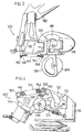
- FIG. 2 is a conceptual diagram of a particular embodiment of a derailleur 100 constructed according to the present invention.
- Derailleur 100 includes a base member 114, a movable member 118, and links 122 and 124 coupling movable member 118 to base member 114 so that movable member 118 is capable of movement relative to base member 114.
- Link 122 is pivotably coupled to base member 114 through a pivot pin 128 and to movable member 118 through a pivot pin 132.
- link 124 is pivotably coupled to base member 114 through a pivot pin 136 and to movable member 118 through a pivot pin 140.
- Base member 114, movable member 118 and links 122 and 124 thus form a four-bar type linkage mechanism.
- a bias spring 144 is mounted to derailleur 100 such that a first end 148 of bias spring 144 is mounted to a mounting post 150 offset from first pivot pin 128.
- a second end 154 of the bias spring is mounted to a mounting post 158 positioned along the path of link 122.
- bias spring 144 is inclined away from the links 122 and 124, and the second end 154 of bias spring 144 is located at an intermediate position of link 122 between pivot pins 128 and 132.
- An actuating arm 155 extends from the side of link 122, and a control element in the form of a cable 156 is connected to the free end of actuating arm 155 for pulling movable member 118 against the biasing force F B of bias spring 144.
- bias spring 144 produces a spring force F S which is inclined to one side of a longitudinal axis X of link 122 away from movable member 118
- control cable 156 produces a control element force F C which is inclined to the opposite side of the longitudinal axis X of link 122 away from movable member 118.
- This connection of the bias spring 144 and control cable 156 removes the substantial forces from the connections at pivot pins 132, 136 and 140, so no bearings are needed at those locations. However, substantial forces still exist at the connection between pivot pin 128 and link 122, so a bearing 162 may be mounted around pivot pin 128 between link 122 and pivot pin 128.
- Figure 3 is a side view of a particular embodiment of an actual derailleur constructed according to the conceptual diagram shown in Figure 2, and Figure 4 is a bottom view of the derailleur shown in Figure 3.
- base member 114 is mounted to a bicycle frame 180, and a movable member 118 supports a chain guide 184 having a guide pulley 186 and a tension pulley 188.
- Bearing 162 is mounted around pivot pins 132, 136 or 140. Instead, links 122 and 124 are allowed to contact pivot pin 132,136 and 140.
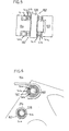
- Figure 5 is a detailed cross sectional view showing the connection between link 122 and base member 114 in the derailleur shown in Figures 3 and 4.
- link 122 includes an upper collar 300 and a lower collar 304.
- a bearing 162 is mounted at each collar 300 and 304.
- Each bearing 162 includes an inner ring 310, an outer ring 314 and a plurality of balls 318 mounted in the annular defined by inner ring 310 and outer ring 314.
- bearing 190 may be mounted around mounting post 158 between mounting post 158 and spring end 154 to reduce this friction, although such a bearing is not mandatory.
- Figure 6 is a detailed view showing how spring end 154 is mounted to mounting post 158 through bearing 190.
- bearing 190 includes an inner ring 320, an outer ring 324 and plurality of balls 328 mounted in the annular space defined by inner ring 320 and outer ring 328.
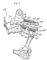
- Figure 7 is a side view of an alternative embodiment of an actual derailleur 200 constructed according to the present invention.
- This embodiment differs from the embodiment shown in Figures 3 and 4 in that two bias springs are used, and the second end of each springs mounted to the pivot pin that connects the upper link to the movable member.
- derailleur 200 includes a base member 214, a movable member 218, and links 222 and 224 coupling movable member 218 to a base member 214 so that movable member 218 is capable of movement relative to base member 214.
- Link 222 is pivotably coupled to base member 214 through a pivot pin 228 and to movable member 218 through a pivot pin 232.
- link 224 is pivotably coupled to base member 214 through a pivot pin 236 and to movable member 218 through a pivot pin 240.
- Base member 214, movable member 218 and links 222 and 224 thus form a four-bar type linkage mechanism.
- a bias spring 244 is mounted to derailleur 200 on one side of link 222 such that a first end 248 of bias spring 244 is mounted to a mounting post 250 offset from first pivot pin 228.
- a second end 254 of bias spring 244 is mounted to a mounting post 258 which, in this embodiment, is an extension of pivot pin 232.
- Another bias spring 270 is mounted on the opposite side of link 222 such that a first end 274 of bias spring 270 is mounted to a mounting post 278 offset from first pivot pin 228.
- a second end 282 of bias spring 270 is mounted to a mounting post 286 which also is an extension of pivot pin 232.
- mounting posts 250 and 278 may be formed as a single post that extends in a straight line through base member 214.
- bearings may be mounted around pivot pin 228 between pivot pin 228 and link 222. In this embodiment, however, substantial pivoting occurs between spring ends 248 and 274 and their associated mounting posts 250 and 278, so further bearings may be mounted around mounting posts 250 and 278 between mounting posts 250, 278 and the corresponding spring ends 248, 274.
- the bearings may be constructed as shown in Figures 5 and 6.
Landscapes
- Engineering & Computer Science (AREA)
- Chemical & Material Sciences (AREA)
- Combustion & Propulsion (AREA)
- Transportation (AREA)
- Mechanical Engineering (AREA)
- Transmission Devices (AREA)
- Transmissions By Endless Flexible Members (AREA)
- Pivots And Pivotal Connections (AREA)
- Motorcycle And Bicycle Frame (AREA)
- Devices For Conveying Motion By Means Of Endless Flexible Members (AREA)
- Gear-Shifting Mechanisms (AREA)
Claims (8)
- Ein Fahrradumwerfer (100), der Folgendes beinhaltet:dadurch gekennzeichnet, dass das erste Ende des ersten Verbindungsglieds (122) an dem Basisteil (114) durch einen zweiten Drehzapfen (128) drehbar montiert ist; und die Feder (144) ein erstes Ende (148), das an dem Basisteil (114) versetzt von dem ersten Drehzapfen (136) und dem zweiten Drehzapfen (128) montiert ist, aufweist, und die Feder (144) eine Federkraft auf einer Seite einer Längsachse (x) des ersten Verbindungsglieds (122) und von dem beweglichen Teil (118) weggerichtet ausübt; und dadurch, dasseinen Basisteil (114);einen beweglichen Teil (118), der eine Kettenführung stützt;ein erstes Verbindungsglied (122), das ein erstes und ein zweites Ende aufweist; wobei das erste Ende des ersten Verbindungsglieds (122) an dem Basisteil (114) beweglich montiert ist und wobei das zweite Ende des ersten Verbindungsglieds (122) an dem beweglichen Teil (118) beweglich montiert ist;ein zweites Verbindungsglied (124), das ein erstes und ein zweites Ende aufweist; wobei das erste Ende des zweiten Verbindungsglieds (124) an dem Basisteil (114) durch einen ersten Drehzapfen (136) drehbar montiert ist und das zweite Ende des zweiten Verbindungsglieds an dem beweglichen Teil (118) beweglich montiert ist; undeine Feder (144),
der Umwerfer (100) ferner einen Steuerelement-Kopplungsteil beinhaltet, der an dem ersten Verbindungsglied (122) zur Kopplung an ein Steuerelement (156), das eine Steuerelementkraft auf eine entgegengesetzte Seite des ersten Verbindungsglieds (122) und von dem beweglichen Teil weggerichtet ausübt, gekoppelt ist. - Umwerfer gemäß Anspruch 1, der ferner ein erstes Lager (162), das an dem zweiten Drehzapfen (128) zwischen dem ersten Ende des ersten Verbindungsglieds (122) und dem zweiten Drehzapfen (128) montiert ist, beinhaltet.
- Umwerfer gemäß einem der vorhergehenden Ansprüche, der ferner einen Betätigungsarm (155), der sich von dem ersten Verbindungsglied (122) erstreckt, beinhaltet, wobei das Steuerelement (156) mit dem Betätigungsarm (155) verbunden ist.
- Umwerfer gemäß einem der vorhergehenden Ansprüche, wobei das zweite Ende des ersten Verbindungsglieds (122) an dem beweglichen Teil (118) durch einen dritten Drehzapfen (132) drehbar montiert ist, und wobei das zweite Ende des zweiten Verbindungsglieds (124) an dem beweglichen Teil (118) durch einen vierten Drehzapfen (140) drehbar montiert ist.
- Umwerfer gemäß Anspruch 4, wobei das zweite Ende des ersten Verbindungsglieds (122) an dem beweglichen Teil (118) drehbar montiert ist, so dass das zweite Ende des ersten Verbindungsglieds (122) mit dem dritten Drehzapfen (132) in Kontakt kommt.
- Umwerfer gemäß Anspruch 4 oder 5, wobei das erste Ende des zweiten Verbindungsglieds (124) an dem Basisteil (114) drehbar montiert ist, so dass das erste Ende des zweiten Verbindungsglieds (124) mit dem ersten Drehzapfen (136) in Kontakt kommt, und wobei das zweite Ende des zweiten Verbindungsglieds (124) an dem beweglichen Teil (118) drehbar montiert ist, so dass das zweite Ende des zweiten Verbindungsglieds (124) mit dem vierten Drehzapfen (140) in Kontakt kommt.
- Umwerfer gemäß einem der vorhergehenden Ansprüche, wobei ein Ende der Feder (144) an dem ersten Verbindungsglied (122) durch einen Montierteil (150) montiert ist, und der ferner ein zweites Lager, das an dem Montierteil (150) zwischen dem Ende der Feder (144) und dem Montierteil (150) montiert ist, beinhaltet.
- Umwerfer gemäß einem der vorhergehenden Ansprüche, wobei ein Ende der Feder (144) an dem Basisteil (114) durch einen Montierteil (150) montiert ist, und der ferner ein drittes Lager, das an dem Montierteil zwischen dem Ende der Feder (144) und dem Montierteil (150) montiert ist, beinhaltet.
Priority Applications (1)
| Application Number | Priority Date | Filing Date | Title |
|---|---|---|---|
| EP02025030A EP1281610B2 (de) | 1997-04-29 | 1998-04-24 | Umwerfer für ein Fahrrad |
Applications Claiming Priority (2)
| Application Number | Priority Date | Filing Date | Title |
|---|---|---|---|
| US08/846,567 US5897451A (en) | 1997-04-29 | 1997-04-29 | Bicycle derailleur having operating forces disposed on opposite sides of a link pivot |
| US846567 | 1997-04-29 |
Related Child Applications (1)
| Application Number | Title | Priority Date | Filing Date |
|---|---|---|---|
| EP02025030A Division EP1281610B2 (de) | 1997-04-29 | 1998-04-24 | Umwerfer für ein Fahrrad |
Publications (2)
| Publication Number | Publication Date |
|---|---|
| EP0875445A1 EP0875445A1 (de) | 1998-11-04 |
| EP0875445B1 true EP0875445B1 (de) | 2003-11-19 |
Family
ID=25298306
Family Applications (2)
| Application Number | Title | Priority Date | Filing Date |
|---|---|---|---|
| EP02025030A Expired - Lifetime EP1281610B2 (de) | 1997-04-29 | 1998-04-24 | Umwerfer für ein Fahrrad |
| EP98303202A Revoked EP0875445B1 (de) | 1997-04-29 | 1998-04-24 | Fahrradkettenschaltung |
Family Applications Before (1)
| Application Number | Title | Priority Date | Filing Date |
|---|---|---|---|
| EP02025030A Expired - Lifetime EP1281610B2 (de) | 1997-04-29 | 1998-04-24 | Umwerfer für ein Fahrrad |
Country Status (10)
| Country | Link |
|---|---|
| US (1) | US5897451A (de) |
| EP (2) | EP1281610B2 (de) |
| JP (1) | JPH10297575A (de) |
| CN (1) | CN1144724C (de) |
| CZ (1) | CZ291457B6 (de) |
| DE (2) | DE69833391T3 (de) |
| PL (1) | PL189239B1 (de) |
| RU (1) | RU2237591C2 (de) |
| SK (1) | SK283776B6 (de) |
| TW (1) | TW412495B (de) |
Cited By (1)
| Publication number | Priority date | Publication date | Assignee | Title |
|---|---|---|---|---|
| US7762916B2 (en) | 2004-06-23 | 2010-07-27 | Shimano Inc. | Front derailleur for bicycle |
Families Citing this family (11)
| Publication number | Priority date | Publication date | Assignee | Title |
|---|---|---|---|---|
| US6093122A (en) * | 1998-01-09 | 2000-07-25 | Sram Corporation | Hybrid spring for bicycle derailleurs |
| US6354971B1 (en) * | 2000-02-02 | 2002-03-12 | Brigham Young University | Compliant derailleur |
| US6757975B1 (en) | 2001-01-25 | 2004-07-06 | Brigham Young University | Multi-layered compliant mechanisms and method of manufacture |
| US20060069360A1 (en) * | 2004-09-29 | 2006-03-30 | Kimberly-Clark Worldwide, Inc. | Absorbent article with insult indicators |
| US7527571B2 (en) | 2004-12-20 | 2009-05-05 | Shimano Inc. | Rear derailleur for bicycle |
| DE102005050988A1 (de) * | 2005-10-25 | 2007-06-14 | Sram Deutschland Gmbh | Kettenumwerfer |
| ITMI20072062A1 (it) * | 2007-10-25 | 2009-04-26 | Campagnolo Srl | Cambio di bicicletta |
| US8678963B2 (en) * | 2011-09-21 | 2014-03-25 | Shimano Inc. | Bicycle front derailleur |
| US9150281B2 (en) * | 2011-09-27 | 2015-10-06 | Shimano Inc. | Bicycle rear derailleur |
| RU2656001C1 (ru) * | 2017-05-03 | 2018-05-30 | Юрий Антонович Петровский | Задний переключатель передач велосипеда |
| RU184897U1 (ru) * | 2018-06-22 | 2018-11-13 | Виктор Николаевич Михалев | Устройство автоматического переключения передач |
Family Cites Families (13)
| Publication number | Priority date | Publication date | Assignee | Title |
|---|---|---|---|---|
| CH190582A (de) * | 1937-02-12 | 1937-04-30 | Zemp Karl | Fahrradwechselgetriebe. |
| FR1319997A (fr) * | 1962-04-20 | 1963-03-01 | Changement de vitesse par déraillement de chaîne, en éléments combinés en matière plastique et en métal pour cycles, tandems, vélomoteurs, motocyclettes ou véhicules similaires | |
| US3748916A (en) * | 1971-06-03 | 1973-07-31 | M Morse | Chain shifting means for derailleur speed changing devices |
| JPS51118237A (en) * | 1975-04-09 | 1976-10-18 | Shimano & Co Ltd | Outside speed change mechanism |
| JPS5247238A (en) * | 1975-10-13 | 1977-04-14 | Shimano Industrial Co | External transmission |
| JPS5383246A (en) * | 1976-12-28 | 1978-07-22 | Shimano Industrial Co | Derailer for bicycle |
| JPS54138252A (en) * | 1978-04-17 | 1979-10-26 | Shimano Industrial Co | Rear derailer for bicycle |
| DE3113700A1 (de) † | 1981-04-04 | 1982-10-21 | Hans Christian Ing.(grad.) 5042 Erftstadt Smolik | Fahrradkettenschaltung |
| DE3400432A1 (de) * | 1984-01-09 | 1985-07-18 | Fichtel & Sachs Ag, 8720 Schweinfurt | Kettenwerfereinrichtung |
| JPH0568797U (ja) * | 1992-02-28 | 1993-09-17 | マエダ工業株式会社 | 自転車用リヤディレーラ |
| DE69423175T2 (de) * | 1993-11-12 | 2000-09-14 | Shimano Inc., Sakai | Vorderer Umwerfer für ein Fahrrad |
| JP3372616B2 (ja) * | 1993-11-30 | 2003-02-04 | 株式会社シマノ | 自転車用ディレーラ |
| US5695421A (en) * | 1996-02-21 | 1997-12-09 | Shimano Inc. | Elastomer coated coil spring and chain derailleur employing same |
-
1997
- 1997-04-29 US US08/846,567 patent/US5897451A/en not_active Expired - Lifetime
-
1998
- 1998-03-31 TW TW087104827A patent/TW412495B/zh not_active IP Right Cessation
- 1998-04-24 EP EP02025030A patent/EP1281610B2/de not_active Expired - Lifetime
- 1998-04-24 DE DE69833391T patent/DE69833391T3/de not_active Expired - Lifetime
- 1998-04-24 DE DE69819810T patent/DE69819810T2/de not_active Revoked
- 1998-04-24 EP EP98303202A patent/EP0875445B1/de not_active Revoked
- 1998-04-28 SK SK560-98A patent/SK283776B6/sk unknown
- 1998-04-28 CZ CZ19981316A patent/CZ291457B6/cs not_active IP Right Cessation
- 1998-04-28 CN CNB981079148A patent/CN1144724C/zh not_active Expired - Fee Related
- 1998-04-29 RU RU98108326/11A patent/RU2237591C2/ru not_active IP Right Cessation
- 1998-04-29 PL PL98326054A patent/PL189239B1/pl not_active IP Right Cessation
- 1998-04-30 JP JP10121106A patent/JPH10297575A/ja active Pending
Cited By (1)
| Publication number | Priority date | Publication date | Assignee | Title |
|---|---|---|---|---|
| US7762916B2 (en) | 2004-06-23 | 2010-07-27 | Shimano Inc. | Front derailleur for bicycle |
Also Published As
| Publication number | Publication date |
|---|---|
| JPH10297575A (ja) | 1998-11-10 |
| DE69819810D1 (de) | 2003-12-24 |
| DE69833391T3 (de) | 2011-03-31 |
| CZ291457B6 (cs) | 2003-03-12 |
| DE69819810T2 (de) | 2004-09-23 |
| PL189239B1 (pl) | 2005-07-29 |
| DE69833391T2 (de) | 2006-10-12 |
| RU2237591C2 (ru) | 2004-10-10 |
| EP1281610B1 (de) | 2006-02-08 |
| CN1144724C (zh) | 2004-04-07 |
| EP1281610B2 (de) | 2010-09-15 |
| EP1281610A2 (de) | 2003-02-05 |
| SK56098A3 (en) | 1998-11-04 |
| PL326054A1 (en) | 1998-11-09 |
| CZ131698A3 (cs) | 1999-11-17 |
| TW412495B (en) | 2000-11-21 |
| EP1281610A3 (de) | 2003-04-16 |
| CN1197745A (zh) | 1998-11-04 |
| DE69833391D1 (de) | 2006-04-20 |
| EP0875445A1 (de) | 1998-11-04 |
| SK283776B6 (sk) | 2004-01-08 |
| US5897451A (en) | 1999-04-27 |
Similar Documents
| Publication | Publication Date | Title |
|---|---|---|
| EP0845408B1 (de) | Hinterradkettenschaltung mit Stossdämpfer | |
| EP0875445B1 (de) | Fahrradkettenschaltung | |
| US4755162A (en) | Derailleur for a bicycle | |
| EP0850829B1 (de) | Hintere Gangschaltung für Fahrrad | |
| EP1099620B1 (de) | Hintere Gangschaltung für Fahrrad mit über eine Rolle geführtem Kabel | |
| US4731045A (en) | Derailleur for a bicycle | |
| EP0814016B1 (de) | Vorderer Umwerfer für ein Fahrrad | |
| US4424048A (en) | Front derailleur for a bicycle having horizontally positioned linkage members | |
| US6419602B1 (en) | Derailleur cable router with a cable housing support that pivots in multiple directions | |
| US4619633A (en) | Derailleur for a bicycle | |
| US4194409A (en) | Front derailleur for a bicycle provided with a swingingly movable chain guide | |
| US4778436A (en) | Front derailleur for a bicycle | |
| US4286953A (en) | Bicycle derailleur having an improved mechanism for swinging a chain guide | |
| EP0018842A2 (de) | Fahrradkettenschaltung mit vermindeter Breite | |
| US4642072A (en) | Derailleur for a bicycle | |
| US6354971B1 (en) | Compliant derailleur | |
| JPS6210874B2 (de) | ||
| US4781657A (en) | Front derailleur for a bicycle | |
| JPH0312634Y2 (de) | ||
| JPH0352398B2 (de) | ||
| JPH0349796B2 (de) |
Legal Events
| Date | Code | Title | Description |
|---|---|---|---|
| PUAI | Public reference made under article 153(3) epc to a published international application that has entered the european phase |
Free format text: ORIGINAL CODE: 0009012 |
|
| 17P | Request for examination filed |
Effective date: 19980511 |
|
| AK | Designated contracting states |
Kind code of ref document: A1 Designated state(s): DE FR IT |
|
| AX | Request for extension of the european patent |
Free format text: AL;LT;LV;MK;RO;SI |
|
| AKX | Designation fees paid |
Free format text: DE FR IT |
|
| 17Q | First examination report despatched |
Effective date: 20020705 |
|
| GRAH | Despatch of communication of intention to grant a patent |
Free format text: ORIGINAL CODE: EPIDOS IGRA |
|
| GRAS | Grant fee paid |
Free format text: ORIGINAL CODE: EPIDOSNIGR3 |
|
| GRAA | (expected) grant |
Free format text: ORIGINAL CODE: 0009210 |
|
| AK | Designated contracting states |
Kind code of ref document: B1 Designated state(s): DE FR IT |
|
| REF | Corresponds to: |
Ref document number: 69819810 Country of ref document: DE Date of ref document: 20031224 Kind code of ref document: P |
|
| ET | Fr: translation filed | ||
| PLBI | Opposition filed |
Free format text: ORIGINAL CODE: 0009260 |
|
| PLAX | Notice of opposition and request to file observation + time limit sent |
Free format text: ORIGINAL CODE: EPIDOSNOBS2 |
|
| 26 | Opposition filed |
Opponent name: SRAM DEUTSCHLAND GMBH Effective date: 20040818 |
|
| PLAX | Notice of opposition and request to file observation + time limit sent |
Free format text: ORIGINAL CODE: EPIDOSNOBS2 |
|
| PLBB | Reply of patent proprietor to notice(s) of opposition received |
Free format text: ORIGINAL CODE: EPIDOSNOBS3 |
|
| RAP2 | Party data changed (patent owner data changed or rights of a patent transferred) |
Owner name: SHIMANO INC. |
|
| APBP | Date of receipt of notice of appeal recorded |
Free format text: ORIGINAL CODE: EPIDOSNNOA2O |
|
| APAH | Appeal reference modified |
Free format text: ORIGINAL CODE: EPIDOSCREFNO |
|
| PLAB | Opposition data, opponent's data or that of the opponent's representative modified |
Free format text: ORIGINAL CODE: 0009299OPPO |
|
| R26 | Opposition filed (corrected) |
Opponent name: SRAM DEUTSCHLAND GMBH Effective date: 20040818 |
|
| APBQ | Date of receipt of statement of grounds of appeal recorded |
Free format text: ORIGINAL CODE: EPIDOSNNOA3O |
|
| PGFP | Annual fee paid to national office [announced via postgrant information from national office to epo] |
Ref country code: DE Payment date: 20070419 Year of fee payment: 10 |
|
| APBU | Appeal procedure closed |
Free format text: ORIGINAL CODE: EPIDOSNNOA9O |
|
| RDAF | Communication despatched that patent is revoked |
Free format text: ORIGINAL CODE: EPIDOSNREV1 |
|
| RDAG | Patent revoked |
Free format text: ORIGINAL CODE: 0009271 |
|
| STAA | Information on the status of an ep patent application or granted ep patent |
Free format text: STATUS: PATENT REVOKED |
|
| 27W | Patent revoked |
Effective date: 20080401 |
|
| PGFP | Annual fee paid to national office [announced via postgrant information from national office to epo] |
Ref country code: FR Payment date: 20080312 Year of fee payment: 11 |
|
| PGFP | Annual fee paid to national office [announced via postgrant information from national office to epo] |
Ref country code: IT Payment date: 20080428 Year of fee payment: 11 |