EP0874933B1 - Semelle de fer a repasser - Google Patents
Semelle de fer a repasser Download PDFInfo
- Publication number
- EP0874933B1 EP0874933B1 EP97900634A EP97900634A EP0874933B1 EP 0874933 B1 EP0874933 B1 EP 0874933B1 EP 97900634 A EP97900634 A EP 97900634A EP 97900634 A EP97900634 A EP 97900634A EP 0874933 B1 EP0874933 B1 EP 0874933B1
- Authority
- EP
- European Patent Office
- Prior art keywords
- heating body
- edge
- sole plate
- plate according
- heel
- Prior art date
- Legal status (The legal status is an assumption and is not a legal conclusion. Google has not performed a legal analysis and makes no representation as to the accuracy of the status listed.)
- Expired - Lifetime
Links
Images


Classifications
-
- D—TEXTILES; PAPER
- D06—TREATMENT OF TEXTILES OR THE LIKE; LAUNDERING; FLEXIBLE MATERIALS NOT OTHERWISE PROVIDED FOR
- D06F—LAUNDERING, DRYING, IRONING, PRESSING OR FOLDING TEXTILE ARTICLES
- D06F75/00—Hand irons
- D06F75/38—Sole plates
Definitions
- the invention relates to an iron soleplate ironing with a heating element from the foundry and having a peripheral edge with a triangular profile defining a toe and a heel, as well as a plate metallic iron of complementary shape having a pointed anterior region and posterior region conforming to the heel and which has an internal face intended to come into thermal contact with the underside of the heating element and a raised border that surrounds laterally the peripheral edge of the heating body which includes assembly means with said edge.
- the object of the invention is in particular to remedy these disadvantages.
- the plate comprising a face outer coated with a coating to form a surface ironing
- the means of assembling the border have at least in the front region of the border a preformed and rolled edge intended to cap the poite of the heating body, and in its posterior region at least a hook intended to come into engagement with the heel of the edge of the heating body.
- the iron soleplate as shown in FIGS. 1 to 4 comprises a heating body 1 coming from foundry, generally molded in a piece of aluminum and incorporating a shielded electrical resistance 2.
- the heating body 1 has a peripheral edge 4 with a general profile triangular defining a point 6 and a heel 8.
- This peripheral edge 4 is practically flat and has a relatively thin and regular thickness except in its slightly higher heel area.
- the sole further comprises a plate 10 ironing iron in a shape complementary to the profile of the heating body 1 and thus having a region pointed anterior 12 and posterior region 14 forming heel.
- Said plate has an internal face 16 intended to come into thermal contact with the face lower 18 of the heating body, and an outer face 20 coated with a coating 22 to constitute a surface of ironing, and a raised edge 24 which surrounds in height the peripheral edge 4 of the heating body 1 and which comprises means of assembly with said edge.
- This plate 10 is preferably made of steel and the coating 22 of plate 10 is, constituted for example, a layer of enamel or chrome which ensures a very good slip of the sole on different textiles.
- This sole thus formed can equip either a dry type iron, i.e. a flat iron vapor in which the plate 10 has, in known manner per se, a plurality of vapor outlet holes such as shown schematically in broken lines in Figure 3.
- a dry type iron i.e. a flat iron vapor in which the plate 10 has, in known manner per se, a plurality of vapor outlet holes such as shown schematically in broken lines in Figure 3.
- the assembly means of the border 24 comprise at least in the anterior region 12 of the border a preformed and rolled edge 26 intended for comb the tip 6 of the heating body, and in the posterior region 14 at least one hook 28 intended for engage heel 8 of edge 4 of the body heating.
- the latter has two hooks 28 as illustrated in Figure 2.
- each hook 28 has a tab, part of which 29 is folded in the direction of the central region of the heating body 1.
- these hooks are obtained by 30 notches in the border 24 so as to allow the folding of the parts 29 of the legs.
- the hook 28 is an elastic element intended to come automatically snap on the heel, this element elastic which may be a tab coming from the edge 24 and having a lateral boss forming a clip.
- the plate 10 previously shaped and coated fragile, enamel or chrome is attached to the peripheral edge 4 of the heating body at its ends, tip and heel, without damaging the lining of the border 24 and therefore the coating of the ironing surface.
- the preformed and rolled edge 26 at proximity of the point present by its shape triangular at an acute angle constituting a pocket, a rigidity which prevents any deformation of the border and therefore any local elongation of the coating, and consequently avoids the creation of micro-cracks.
- stresses exerted on the hooks 28 are very localized and only exerted on the parts horizontal 29 of the legs which, at the end of manufacture of the iron, will be hidden by the case.
- the rolled edge 26 of the edge 24 also extends laterally to the large lateral edges 32 of the heating body, and at a distance from these edges with a small clearance ⁇ .
- the plate 10 and the heating body 1 are maintained at an angle ⁇ .
- the point 6 of the edge 4 is fitted under the rolled edge 26 of the anterior region of the edge 24.
- the the lower 18 and inner 16 respectively of the heating body 1 and of the plate 10 are applied against each other and the assembly thus formed is maintained by placing the hooks 28 on the heel 8.
- This hooks are put in place by folding the parts 29 on the heel 8.
- This fixing around the pivot point formed by the tip 6 and the rolled edge 26 allows an almost intimate application by the layer of silicone adhesive with the face lower 18 of the heating body since the application force is controlled at the level of the hooks 28.
- this method offers as advantages main simplicity of manufacture, and warranty the quality of the ironing surface both manufacturing, only in long-term use.
Description
- la figure 1 est une vue schématique en coupe verticale selon la ligne brisée I/I de la figure 2 d'une semelle selon l'invention comportant un corps chauffant et une plaque de repassage;
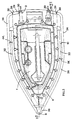
- la figure 2 représente en vue de dessus la semelle de la figure 1;
- la figure 3 illustre en vue de dessus la plaque de repassage seule;
- la figure 4 représente le corps chauffant et la plaque de repassage dans une phase d'assemblage de la semelle selon l'invention.
Claims (9)
- Semelle de fer à repasser comportant un corps chauffant (1) venu de fonderie et présentant un bord périphérique (4) à profil général triangulaire définissant une pointe (6) et un talon (8), ainsi qu'une plaque métallique (10) de repassage de forme complémentaire ayant une région antérieure pointue (12) et une région postérieure (14) formant talon et qui comporte une face interne (16) destinée à venir en contact thermique avec la face inférieure (18) du corps chauffant (1), , et une bordure (24) relevée entourant latéralement le bord périphérique (4) du corps chauffant et qui comporte des moyens d'assemblage avec ledit bord,
caractrisée en ce que la plaque (10) comportant une face externe (20) revêtue d'un revêtement (22) pour constituer une surface de repassage les moyens d'assemblage de la bordure (24) comportent au moins dans la région antérieure (12) de la bordure un bord préformé et roulé (26) destiné à venir coiffer la poite (6) du corps chauffant, et dans sa région postérieure (14) au moins un crochet (28) destiné à venir en prise avec le talon (8) du bord (4) du corps chauffant. - Semelle de fer à repasser selon la revendication 1,
caractérisée en ce que le crochet (28) comporte une patte dont une partie (29) est pliée en direction de la région centrale du corps chauffant (1). - Semelle de fer à repasser selon la revendication 1,
caractérisée en ce que le crochet (28) est un élément élastique destiné à venir s'encliqueter automatiquement sur le talon (8). - Semelle de fer à repasser selon l'une quelconque des revendications précédentes,
caractérisée en ce que le bord préformé et roulé (26) de la bordure (24) s'étend également latéralement aux grands bords latéraux (32) du corps chauffant (1). - Semelle de fer à repasser selon la revendication 4,
caractérisée en ce que le bord préformé et roulé (26) s'étend à distance des bords latéraux (32) selon un faible jeu (α). - Semelle de fer à repasser selon l'une quelconque des revendications précédentes,
caractérisée en ce que sur la face inférieure (18) du corps chauffant (1) est appliqué une couche de colle silicone. - Semelle de fer à repasser selon l'une quelconque des revendications précédentes,
caractérisée en ce que le revêtement (22) est formé par une couche de chrome. - Semelle de fer à repasser selon l'une quelconque des revendications 1 à 6,
caractérisée en ce que le revêtement (22) est une couche d'émail. - Procédé de réalisation d'une semelle selon l'une quelconque des revendications précédentes et dans laquelle la plaque (10) a été préalablement conformée avec son bord roulé puis recouverte sur la totalité de la face externe (20) d'un revêtement,
caractérisé en ce que, l'on maintient selon un angle β la plaque (10) et le corps chauffant (1); l'on emboíte la pointe (6) du bord périphérique (4) sous le bord roulé (26) de la région antérieure de la bordure (24), puis l'on applique l'une contre l'autre les faces inférieure (18) et un interne (16) respectivement du corps chauffant (1) et de la plaque (10), et l'on maintient l'ensemble ainsi constitué par la mise en place du crochet (28) sur le talon (8).
Applications Claiming Priority (3)
| Application Number | Priority Date | Filing Date | Title |
|---|---|---|---|
| FR9600498 | 1996-01-17 | ||
| FR9600498A FR2743578B1 (fr) | 1996-01-17 | 1996-01-17 | Semelle de fer a repasser |
| PCT/FR1997/000053 WO1997026399A2 (fr) | 1996-01-17 | 1997-01-13 | Semelle de fer a repasser |
Publications (2)
| Publication Number | Publication Date |
|---|---|
| EP0874933A2 EP0874933A2 (fr) | 1998-11-04 |
| EP0874933B1 true EP0874933B1 (fr) | 2000-06-14 |
Family
ID=9488190
Family Applications (1)
| Application Number | Title | Priority Date | Filing Date |
|---|---|---|---|
| EP97900634A Expired - Lifetime EP0874933B1 (fr) | 1996-01-17 | 1997-01-13 | Semelle de fer a repasser |
Country Status (7)
| Country | Link |
|---|---|
| US (1) | US6134817A (fr) |
| EP (1) | EP0874933B1 (fr) |
| CN (1) | CN1260013A (fr) |
| DE (1) | DE69702300T2 (fr) |
| FR (1) | FR2743578B1 (fr) |
| RU (1) | RU2167230C2 (fr) |
| WO (1) | WO1997026399A2 (fr) |
Families Citing this family (3)
| Publication number | Priority date | Publication date | Assignee | Title |
|---|---|---|---|---|
| ES2338846B1 (es) * | 2008-08-28 | 2011-02-18 | Bsh Krainel, S.A | Suela de plancha, dispositivo de planchado, asi como procedimiento para la fabricacion de una suela de plancha. |
| ES2389410B1 (es) | 2011-03-30 | 2013-09-16 | BSH Electrodomésticos España S.A. | Suela de plancha y procedimiento de fabricación de una suela de plancha |
| CN106592189B (zh) * | 2016-12-13 | 2019-10-25 | 安徽省煜灿新型材料科技有限公司 | 一种耐磨防粘熨斗底板及制备方法 |
Family Cites Families (15)
| Publication number | Priority date | Publication date | Assignee | Title |
|---|---|---|---|---|
| US863861A (en) * | 1906-05-11 | 1907-08-20 | John J Lucas | Sad-iron. |
| GB191006439A (en) * | 1910-04-26 | 1910-11-17 | Albert Hateley | Improvements in connection with Sad Irons. |
| DE390606C (de) * | 1919-11-07 | 1924-02-21 | Prometheus Akt Ges Fuer Elek S | Elektrisches Buegeleisen |
| US1963858A (en) * | 1932-10-27 | 1934-06-19 | Meidell Birger Oivind | Steam developing device for flatirons |
| US2142032A (en) * | 1937-04-30 | 1938-12-27 | Marcus J Matsen | Presser shoe |
| US2299322A (en) * | 1941-03-24 | 1942-10-20 | Mabel B Harter | Ironing apparatus |
| US2846793A (en) * | 1955-04-21 | 1958-08-12 | Hoover Co | Smoothing iron soleplate |
| DE1939634U (de) * | 1964-08-01 | 1966-06-02 | Siemens Elektrogeraete Gmbh | Buegeleisen, insbesondere elektrisches buegeleisen. |
| US3584366A (en) * | 1968-08-07 | 1971-06-15 | Wallace Expanding Machines | Process for manufacture of shadow mask frames |
| US3783538A (en) * | 1973-03-20 | 1974-01-08 | Arnim D Von | Steaming and ironing appliance |
| FR2581402B1 (fr) * | 1985-05-02 | 1988-03-25 | Seb Sa | Semelle de fer a repasser recouverte par un revetement d'email |
| GB2225345A (en) * | 1988-10-21 | 1990-05-30 | Russell Hobbs Tower Limited | Electrically heated irons with composite sole plate |
| FR2687416B1 (fr) * | 1992-02-17 | 1994-09-02 | Moulinex Sa | Semelle de fer a repasser et son procede de fabrication. |
| WO1994018372A1 (fr) * | 1993-02-02 | 1994-08-18 | Designodev Limited | Ensemble semelle et plaque de base de fer a repasser |
| FR2718467B1 (fr) * | 1994-04-08 | 1996-11-29 | Moulinex Sa | Fer à repasser comportant une semelle rapportée. |
-
1996
- 1996-01-17 FR FR9600498A patent/FR2743578B1/fr not_active Expired - Fee Related
-
1997
- 1997-01-13 WO PCT/FR1997/000053 patent/WO1997026399A2/fr active IP Right Grant
- 1997-01-13 EP EP97900634A patent/EP0874933B1/fr not_active Expired - Lifetime
- 1997-01-13 DE DE69702300T patent/DE69702300T2/de not_active Expired - Fee Related
- 1997-01-13 CN CN97192884.3A patent/CN1260013A/zh active Pending
- 1997-01-13 US US09/101,814 patent/US6134817A/en not_active Expired - Fee Related
- 1997-01-13 RU RU98115840/12A patent/RU2167230C2/ru not_active IP Right Cessation
Also Published As
| Publication number | Publication date |
|---|---|
| WO1997026399A2 (fr) | 1997-07-24 |
| WO1997026399A3 (fr) | 2002-10-03 |
| FR2743578A1 (fr) | 1997-07-18 |
| DE69702300T2 (de) | 2001-02-15 |
| DE69702300D1 (de) | 2000-07-20 |
| EP0874933A2 (fr) | 1998-11-04 |
| FR2743578B1 (fr) | 1999-06-11 |
| CN1260013A (zh) | 2000-07-12 |
| RU2167230C2 (ru) | 2001-05-20 |
| US6134817A (en) | 2000-10-24 |
Similar Documents
| Publication | Publication Date | Title |
|---|---|---|
| EP0400277B1 (fr) | Tête de club de golf et procédé de fabrication de celle-ci | |
| EP0682724B1 (fr) | Semelle de fer a repasser multicouches en materiaux colamines | |
| EP0774283B2 (fr) | Châssis pour patin et procédé de fabrication | |
| EP0418167B1 (fr) | Eclisse rapide pour chemin de câble en fils soudés | |
| EP0874933B1 (fr) | Semelle de fer a repasser | |
| EP0556721B1 (fr) | Semelle de fer à repasser et son procédé de fabrication | |
| CA2244503C (fr) | Dispositif de fixation de pieces d'un appareil electromenager | |
| EP2020365B1 (fr) | Panneau élémentaire avantageusement en forme d'un profilé, notamment pour former une paroi latérale d'un espace de chargement de produits d'un véhicule | |
| FR2845168A1 (fr) | Monture de lunettes transformable et element de transformation associe | |
| FR2766905A1 (fr) | Profile a rainure(s) pour la mise en place d'au moins un accessoire | |
| EP2665399B1 (fr) | Dispositif amovible de préhension d'un ustensile de cuisson | |
| FR2768471A1 (fr) | Dispositif pour la fixation d'un objet sur une surface, notamment sur un mur ou un plancher, a l'aide d'un mastic-colle | |
| FR2727440A1 (fr) | Fer a repasser comportant une semelle amelioree | |
| FR2548305A1 (fr) | Agencement de ressort sur une machoire de frein a disque a garnitures partielles | |
| WO1996024233A1 (fr) | Element chauffant avec plaque diffusante et procede d'assemblage dudit ensemble | |
| FR2580483A1 (fr) | Ensemble formant revetement d'habillage pour un siege et procede pour sa fabrication | |
| EP1972243B1 (fr) | Dispositif de fixation de poignée d'epaisseur reduite sur un article culinaire | |
| FR2705374A1 (fr) | Semelle pour un fer à repasser électrique. | |
| FR2718467A1 (fr) | Fer à repasser comportant une semelle rapportée. | |
| FR2766904A1 (fr) | Profile a section transversale du type en c susceptible d'etre associe a lui-meme par emboitement | |
| CA2626141C (fr) | Dispositif de fixation de poignee sur un article culinaire avec capot anti projection | |
| EP3031979B1 (fr) | Fer à repasser comportant un corps et une plaque de semelle métallique rapportée contre le corps | |
| FR2514466A1 (fr) | Bloc optique, notamment de projecteur de vehicule automobile | |
| FR2614949A1 (fr) | Recipient a anses tenantes comprenant une partie rapportee | |
| FR2734507A1 (fr) | Manche d'ustensile pourvu d'une decoration laterale |
Legal Events
| Date | Code | Title | Description |
|---|---|---|---|
| PUAI | Public reference made under article 153(3) epc to a published international application that has entered the european phase |
Free format text: ORIGINAL CODE: 0009012 |
|
| 17P | Request for examination filed |
Effective date: 19980817 |
|
| AK | Designated contracting states |
Kind code of ref document: A2 Designated state(s): DE GB IT NL |
|
| 17Q | First examination report despatched |
Effective date: 19990208 |
|
| GRAG | Despatch of communication of intention to grant |
Free format text: ORIGINAL CODE: EPIDOS AGRA |
|
| GRAG | Despatch of communication of intention to grant |
Free format text: ORIGINAL CODE: EPIDOS AGRA |
|
| GRAH | Despatch of communication of intention to grant a patent |
Free format text: ORIGINAL CODE: EPIDOS IGRA |
|
| GRAH | Despatch of communication of intention to grant a patent |
Free format text: ORIGINAL CODE: EPIDOS IGRA |
|
| GRAA | (expected) grant |
Free format text: ORIGINAL CODE: 0009210 |
|
| AK | Designated contracting states |
Kind code of ref document: B1 Designated state(s): DE GB IT NL |
|
| PG25 | Lapsed in a contracting state [announced via postgrant information from national office to epo] |
Ref country code: NL Free format text: LAPSE BECAUSE OF FAILURE TO SUBMIT A TRANSLATION OF THE DESCRIPTION OR TO PAY THE FEE WITHIN THE PRESCRIBED TIME-LIMIT Effective date: 20000614 Ref country code: IT Free format text: LAPSE BECAUSE OF FAILURE TO SUBMIT A TRANSLATION OF THE DESCRIPTION OR TO PAY THE FEE WITHIN THE PRE;WARNING: LAPSES OF ITALIAN PATENTS WITH EFFECTIVE DATE BEFORE 2007 MAY HAVE OCCURRED AT ANY TIME BEFORE 2007. THE CORRECT EFFECTIVE DATE MAY BE DIFFERENT FROM THE ONE RECORDED.SCRIBED TIME-LIMIT Effective date: 20000614 |
|
| GBT | Gb: translation of ep patent filed (gb section 77(6)(a)/1977) |
Effective date: 20000615 |
|
| REF | Corresponds to: |
Ref document number: 69702300 Country of ref document: DE Date of ref document: 20000720 |
|
| NLV1 | Nl: lapsed or annulled due to failure to fulfill the requirements of art. 29p and 29m of the patents act | ||
| PLBE | No opposition filed within time limit |
Free format text: ORIGINAL CODE: 0009261 |
|
| STAA | Information on the status of an ep patent application or granted ep patent |
Free format text: STATUS: NO OPPOSITION FILED WITHIN TIME LIMIT |
|
| 26N | No opposition filed | ||
| REG | Reference to a national code |
Ref country code: GB Ref legal event code: IF02 |
|
| PGFP | Annual fee paid to national office [announced via postgrant information from national office to epo] |
Ref country code: DE Payment date: 20020129 Year of fee payment: 6 |
|
| PUAK | Availability of information related to the publication of the international search report |
Free format text: ORIGINAL CODE: 0009015 |
|
| AK | Designated contracting states |
Kind code of ref document: A3 Designated state(s): DE GB IT NL |
|
| PGFP | Annual fee paid to national office [announced via postgrant information from national office to epo] |
Ref country code: GB Payment date: 20030124 Year of fee payment: 7 |
|
| PG25 | Lapsed in a contracting state [announced via postgrant information from national office to epo] |
Ref country code: DE Free format text: LAPSE BECAUSE OF NON-PAYMENT OF DUE FEES Effective date: 20030801 |
|
| PG25 | Lapsed in a contracting state [announced via postgrant information from national office to epo] |
Ref country code: GB Free format text: LAPSE BECAUSE OF NON-PAYMENT OF DUE FEES Effective date: 20040113 |
|
| GBPC | Gb: european patent ceased through non-payment of renewal fee |
Effective date: 20040113 |