EP0874363B1 - Magnetbandkassettengerät - Google Patents
Magnetbandkassettengerät Download PDFInfo
- Publication number
- EP0874363B1 EP0874363B1 EP98201202A EP98201202A EP0874363B1 EP 0874363 B1 EP0874363 B1 EP 0874363B1 EP 98201202 A EP98201202 A EP 98201202A EP 98201202 A EP98201202 A EP 98201202A EP 0874363 B1 EP0874363 B1 EP 0874363B1
- Authority
- EP
- European Patent Office
- Prior art keywords
- magnetic tape
- tape cassette
- winding
- mandrels
- cassette apparatus
- Prior art date
- Legal status (The legal status is an assumption and is not a legal conclusion. Google has not performed a legal analysis and makes no representation as to the accuracy of the status listed.)
- Expired - Lifetime
Links
Images
Classifications
-
- G—PHYSICS
- G11—INFORMATION STORAGE
- G11B—INFORMATION STORAGE BASED ON RELATIVE MOVEMENT BETWEEN RECORD CARRIER AND TRANSDUCER
- G11B15/00—Driving, starting or stopping record carriers of filamentary or web form; Driving both such record carriers and heads; Guiding such record carriers or containers therefor; Control thereof; Control of operating function
- G11B15/18—Driving; Starting; Stopping; Arrangements for control or regulation thereof
- G11B15/26—Driving record carriers by members acting directly or indirectly thereon
- G11B15/32—Driving record carriers by members acting directly or indirectly thereon through the reels or cores on to which the record carrier is wound
Definitions
- the invention relates to a magnetic tape cassette device with a drive, the having rotatably mounted about bearing axes winding mandrels, which are adapted for engagement in Winding openings of the magnetic tape cassette are provided and the over its circumference distributed have at least one driving rib, wherein the mandrels axially in an axial displacement area slidably attached to the bearing axes and in each case by means of at least one spring in the direction of a preferred axial position are biased.
- Such a magnetic tape cassette apparatus is known from US 4,609,164.
- This known magnetic tape cassette device has rotatably mounted about bearing axes Mandrels on.
- the mandrels engage with spring lugs in a radial groove of the Bearing axes, whereby the axial position of the mandrels is precisely defined.
- the mandrels have drive ribs, which are connected to the winding bodies of the Magnetic tape cassette existing entrainment of such interaction that at Rotation of the mandrels, the winding body of the cassette are rotated.
- a magnetic tape cassette apparatus of the aforementioned Art to create, which facilitates the lowering of a cassette on the winding mandrels and malfunction when lowering the cartridge on the mandrels avoids.
- the Mandrels at the beginning of a jamming or jamming between the Winding bodies of the cassette and the mandrels axially in the lowering direction of the Dodge magnetic tape cassette and prevent jamming or jamming. This is a reliable lowering of the cassette on the winding mandrels guaranteed.
- the mandrels are in the preferred axial position pressed. This preferred axial position is the axial position of the mandrels, the Playing the cassette is provided and in particular by the axial height of the Magnetic head is determined.
- An advantageous embodiment of the invention is characterized in that the Springs are each arranged between the bearing axes and the mandrels and that the springs under support on the bearing axles and / or on bearing elements of a Press the chassis plate axially against the mandrels.
- the spring is designed so that it presses in the axial direction against the mandrels and is guided radially on the bearing axis.
- the axial force serves both the axial bias of the mandrels in the direction of the Preferred axial position as well as for generating a friction torque on the mandrel, whereby aelleszugmoment is generated. This counter moment keeps that Magnetic tape of the magnetic tape cassette taut in the game mode.
- the Springs are integrally formed.
- the having integrally formed spring at least three spring arms.
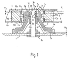
- FIG. 1 shows a chassis plate 1 of a drive of a magnetic tape cassette apparatus, in which a bearing pin 3 by means of plastic fasteners 3a in outsert molding technology is attached.
- the bearing pin 3 has near its upper end 3b a radial groove 3c with an axial height H1.
- On the bearing pin 3 is a Winding mandrel 5 attached.
- the winding mandrel 5 has a foot 5a of conical Shape having a base 5c. Above the foot 5a is a cylindrical body 5d, which at its upper end 5e with a tapered oblique surface 5f expires.
- the mandrel 5 has the circumference distributes three driving ribs 10a, 10b and 10c, of which in Fig. 1 a first driving rib 10a is shown.
- the bearing pin 3 is within the main body 5d in a guide bush 5h the winding mandrel 5 out.
- the winding mandrel 5 has spring lugs 5i, which with Projections 5j engage in the radial groove 3c of the bearing pin 3.
- the projections 5j have an axial height H2.
- the axial height H2 of the projections 5j is smaller as the axial height H1 of the radial groove 3c of the bearing pin 3. This is the Winding mandrel 5 in the axial direction slidably attached to the bearing pin 3.
- the foot 5a of the winding mandrel 5 has a cavity 7, in which a schematically illustrated spring 9 is arranged.
- This is shown schematically Spring 9 is supported on the chassis plate 1, on the winding mandrel 5 and on the Bearing pin 3 off.
- the spring 9 exerts an axial force on the mandrel 5 and pushes the winding mandrel 5 within the radial groove 3c upwards, so that the Upper edge 5k of the projections 5j of the spring lugs 5i against the upper edge 3d of radial guide groove 3c presses.
- Between the base 5 c of the winding mandrel. 5 and the chassis plate 3 is an air gap of height H3.
- the height is H3 greater than or equal to the difference in heights H1 and H2.
- the Magnetic tape cassette 11 On the winding mandrel 5, a magnetic tape cassette 11 is placed.
- the Magnetic tape cassette 11 has an upper cover wall 11a and a lower Deckwnad 11b.
- openings 11c are provided through which the illustrated Winding mandrel 5 passes through.
- Inside the magnetic tape cassette 11 are two coil winding body 13 arranged side by side, through the central Breakthroughs 13a, the mandrels 5 can reach through.
- the central Openings 13a of the coil winding body 13 are radially into the openings 13a Provided in-reach driving lugs 13b.
- the driving lugs 13b of the coil winding body 13 of the cassette slide down on the conical inclined surfaces 5f of the winding mandrel 5 and in the region of the conical inclined surfaces 5f of the winding mandrel 5, there can be no jamming or jamming. Tilts or jamming occur only when the driving lugs 13b of the winding body 13 come to rest on the driving ribs 10a, 10b and 10c. Then, the mandrel 5 is pressed from the preferred axial position in a lowered position down.
- the catch lugs 13b of the coil winding body 13 of the cassette 11 are then not in engagement with the driving ribs 10a, 10b and 10c and therefore do not rotate when the winding mandrel 5 is driven in its lowered position.
- the winding mandrel 5 is further rotated by a drive wheel, not shown, whereby the driving ribs 10a, 10b and 10c between the driving lugs 13b of the coil winding body 13 and the winding mandrel 5 can jump due to the force of the spring 9 from the lowered position back into the preferred axial position.
- the spring 9 causes in addition to the axial bias of the winding mandrel 5 simultaneously a Schmidtmoment, by which the magnetic tape of the magnetic tape cassette 11th held tight in the game mode. This counter moment arises when turning the winding mandrel 5 both by friction between the spring 9 and the Winding mandrel 5 as well as by friction between the radial groove 3c and the Projections 5j of the spring lugs 5i.
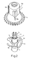
- Fig. 2 shows an exploded perspective view of the winding mandrel 5, the Bearing pin 3 and the spring 9.
- the spring 9 is integrally formed, has three Spring arms 9a, 9b and 9c, presses with these spring arms axially against the Winding mandrel 5 and is guided radially by means of a central hole 9d.
- winding mandrel 5 a ring gear 14.
- the winding mandrel 5 by a drive gear, not shown, rotating are driven.
Landscapes
- Winding Of Webs (AREA)
Applications Claiming Priority (2)
| Application Number | Priority Date | Filing Date | Title |
|---|---|---|---|
| DE19717777 | 1997-04-26 | ||
| DE19717777A DE19717777A1 (de) | 1997-04-26 | 1997-04-26 | Magnetbandkassettengerät |
Publications (3)
| Publication Number | Publication Date |
|---|---|
| EP0874363A2 EP0874363A2 (de) | 1998-10-28 |
| EP0874363A3 EP0874363A3 (de) | 1999-03-31 |
| EP0874363B1 true EP0874363B1 (de) | 2005-07-27 |
Family
ID=7827900
Family Applications (1)
| Application Number | Title | Priority Date | Filing Date |
|---|---|---|---|
| EP98201202A Expired - Lifetime EP0874363B1 (de) | 1997-04-26 | 1998-04-15 | Magnetbandkassettengerät |
Country Status (4)
| Country | Link |
|---|---|
| US (1) | US5901915A (enExample) |
| EP (1) | EP0874363B1 (enExample) |
| JP (1) | JPH10334545A (enExample) |
| DE (2) | DE19717777A1 (enExample) |
Families Citing this family (2)
| Publication number | Priority date | Publication date | Assignee | Title |
|---|---|---|---|---|
| KR100697756B1 (ko) | 1999-04-26 | 2007-03-21 | 소니 가부시끼 가이샤 | 광 디스크 및 그 제조 방법 |
| US20050006513A1 (en) * | 2003-07-01 | 2005-01-13 | Hewlett-Packard Development Company, L.P. | Apparatus for centering a tape cartridge hub |
Family Cites Families (12)
| Publication number | Priority date | Publication date | Assignee | Title |
|---|---|---|---|---|
| JPS4952510U (enExample) * | 1972-08-11 | 1974-05-09 | ||
| JPS5824306Y2 (ja) * | 1979-04-10 | 1983-05-24 | オリンパス光学工業株式会社 | カセットの磁気記録テ−プ弛み防止機構 |
| US4695011A (en) * | 1980-12-26 | 1987-09-22 | Pioneer Electronic Corporation | Cassette tape machine |
| DE3151742A1 (de) * | 1980-12-29 | 1982-09-02 | Pioneer Electronic Corp., Tokyo | Kassettenbandgeraet |
| JPS5839758U (ja) * | 1981-09-07 | 1983-03-15 | パイオニア株式会社 | カセツト式テ−プレコ−ダ |
| US4413919A (en) * | 1981-10-30 | 1983-11-08 | International Business Machines Corporation | Ribbon loading system for printers |
| JPS58131480U (ja) * | 1982-02-26 | 1983-09-05 | 松下電器産業株式会社 | テ−プカセツト |
| JPH0424549Y2 (enExample) * | 1984-10-29 | 1992-06-10 | ||
| JPH0685242B2 (ja) * | 1985-05-23 | 1994-10-26 | ソニー株式会社 | リ−ル台 |
| US5183219A (en) * | 1988-11-15 | 1993-02-02 | Schlumberger Industries | Coupling for axially locking a reel of a tape cassette and for driving it without backlash |
| JPH0740395B2 (ja) * | 1989-04-11 | 1995-05-01 | 三菱電機株式会社 | カセットローディング装置 |
| DE4405153C2 (de) * | 1994-02-18 | 1996-07-11 | Philips Patentverwaltung | Magnetbandkassettengerät mit einem Laufwerk zum Abspielen von Magnetbandkassetten |
-
1997
- 1997-04-26 DE DE19717777A patent/DE19717777A1/de not_active Withdrawn
-
1998
- 1998-04-15 DE DE59812950T patent/DE59812950D1/de not_active Expired - Fee Related
- 1998-04-15 EP EP98201202A patent/EP0874363B1/de not_active Expired - Lifetime
- 1998-04-23 US US09/065,793 patent/US5901915A/en not_active Expired - Fee Related
- 1998-04-27 JP JP10116606A patent/JPH10334545A/ja active Pending
Also Published As
| Publication number | Publication date |
|---|---|
| EP0874363A3 (de) | 1999-03-31 |
| US5901915A (en) | 1999-05-11 |
| JPH10334545A (ja) | 1998-12-18 |
| DE59812950D1 (de) | 2005-09-01 |
| DE19717777A1 (de) | 1998-10-29 |
| EP0874363A2 (de) | 1998-10-28 |
Similar Documents
| Publication | Publication Date | Title |
|---|---|---|
| DE69016201T2 (de) | Vorrichtung zum radialen zentrifugalen Zuführen der Fäden des Schneidkopfes von Fadenschneider oder dergleichen. | |
| DE69916014T2 (de) | Verfahren und vorrichtung zum zusammenbau eines sitzes für einen selbstfahrenden rasenmäher | |
| DE3506748C2 (enExample) | ||
| DE2706194C2 (enExample) | ||
| DE9213187U1 (de) | Drehverschluß für einen Sportschuh | |
| EP0673212A1 (de) | Schuhverschluss. | |
| DE3886498T2 (de) | Kurbelvorrichtung. | |
| DE10302549A1 (de) | Türfeststeller | |
| DE29914341U1 (de) | Drehknopf-Schalteinrichtung | |
| DE2631043A1 (de) | Vorrichtung zum oeffnen und schliessen von schnurbetaetigten verschluessen | |
| DE2740300C2 (de) | Kassettentonbandgerät | |
| DE3323150C2 (enExample) | ||
| DE2448479A1 (de) | Antriebsvorrichtung fuer einen magnetkopf | |
| EP0874363B1 (de) | Magnetbandkassettengerät | |
| DE60029884T2 (de) | Aufzeichnungsmedium-Wiedergabegerät | |
| DE3140088C2 (enExample) | ||
| DE1235617B (de) | Tonbandwechsler | |
| DE2403174B2 (de) | Rastwerk für Stufendrehschalter mit einer Spring-Return-Vorrichtung bei der die Feder gegen in Nuten eingesetzte Plättchen anschlägt | |
| DE4125076C2 (de) | Farbbandregenerierungsvorrichtung | |
| DE69517156T2 (de) | Aufzeichnungs- und/oder wiedergabegerät für gebrauch mit magnetbandkassetten von verschiedenen grössen | |
| DE19723031A1 (de) | Hebezeug | |
| DE2706022A1 (de) | Einstellvorrichtung fuer einen fahrzeugrueckspiegel | |
| DE69921494T2 (de) | Anlage zum Abtragen von Elektrodenspitzen | |
| DE19540627A1 (de) | Federangetriebener Aufroller für Sicherheitsgurte | |
| DE3688865T2 (de) | Kassettenaufnahme- und Wiedergabegerät. |
Legal Events
| Date | Code | Title | Description |
|---|---|---|---|
| PUAI | Public reference made under article 153(3) epc to a published international application that has entered the european phase |
Free format text: ORIGINAL CODE: 0009012 |
|
| AK | Designated contracting states |
Kind code of ref document: A2 Designated state(s): DE FR GB |
|
| AX | Request for extension of the european patent |
Free format text: AL;LT;LV;MK;RO;SI |
|
| PUAL | Search report despatched |
Free format text: ORIGINAL CODE: 0009013 |
|
| AK | Designated contracting states |
Kind code of ref document: A3 Designated state(s): AT BE CH CY DE DK ES FI FR GB GR IE IT LI LU MC NL PT SE |
|
| AX | Request for extension of the european patent |
Free format text: AL;LT;LV;MK;RO;SI |
|
| 17P | Request for examination filed |
Effective date: 19990930 |
|
| AKX | Designation fees paid |
Free format text: DE FR GB |
|
| RAP3 | Party data changed (applicant data changed or rights of an application transferred) |
Owner name: KONINKLIJKE PHILIPS ELECTRONICS N.V. Owner name: PHILIPS CORPORATE INTELLECTUAL PROPERTY GMBH |
|
| RAP1 | Party data changed (applicant data changed or rights of an application transferred) |
Owner name: KONINKLIJKE PHILIPS ELECTRONICS N.V. Owner name: PHILIPS CORPORATE INTELLECTUAL PROPERTY GMBH |
|
| RAP1 | Party data changed (applicant data changed or rights of an application transferred) |
Owner name: KONINKLIJKE PHILIPS ELECTRONICS N.V. Owner name: PHILIPS INTELLECTUAL PROPERTY & STANDARDS GMBH |
|
| 17Q | First examination report despatched |
Effective date: 20030702 |
|
| GRAP | Despatch of communication of intention to grant a patent |
Free format text: ORIGINAL CODE: EPIDOSNIGR1 |
|
| GRAS | Grant fee paid |
Free format text: ORIGINAL CODE: EPIDOSNIGR3 |
|
| GRAA | (expected) grant |
Free format text: ORIGINAL CODE: 0009210 |
|
| AK | Designated contracting states |
Kind code of ref document: B1 Designated state(s): DE FR GB |
|
| REG | Reference to a national code |
Ref country code: GB Ref legal event code: FG4D Free format text: NOT ENGLISH |
|
| REF | Corresponds to: |
Ref document number: 59812950 Country of ref document: DE Date of ref document: 20050901 Kind code of ref document: P |
|
| GBT | Gb: translation of ep patent filed (gb section 77(6)(a)/1977) |
Effective date: 20050926 |
|
| REG | Reference to a national code |
Ref country code: GB Ref legal event code: 746 Effective date: 20050928 |
|
| ET | Fr: translation filed | ||
| PLBE | No opposition filed within time limit |
Free format text: ORIGINAL CODE: 0009261 |
|
| STAA | Information on the status of an ep patent application or granted ep patent |
Free format text: STATUS: NO OPPOSITION FILED WITHIN TIME LIMIT |
|
| 26N | No opposition filed |
Effective date: 20060428 |
|
| PGFP | Annual fee paid to national office [announced via postgrant information from national office to epo] |
Ref country code: DE Payment date: 20070612 Year of fee payment: 10 |
|
| PGFP | Annual fee paid to national office [announced via postgrant information from national office to epo] |
Ref country code: GB Payment date: 20070425 Year of fee payment: 10 |
|
| PGFP | Annual fee paid to national office [announced via postgrant information from national office to epo] |
Ref country code: FR Payment date: 20070425 Year of fee payment: 10 |
|
| GBPC | Gb: european patent ceased through non-payment of renewal fee |
Effective date: 20080415 |
|
| PG25 | Lapsed in a contracting state [announced via postgrant information from national office to epo] |
Ref country code: DE Free format text: LAPSE BECAUSE OF NON-PAYMENT OF DUE FEES Effective date: 20081101 |
|
| REG | Reference to a national code |
Ref country code: FR Ref legal event code: ST Effective date: 20081231 |
|
| PG25 | Lapsed in a contracting state [announced via postgrant information from national office to epo] |
Ref country code: FR Free format text: LAPSE BECAUSE OF NON-PAYMENT OF DUE FEES Effective date: 20080430 |
|
| PG25 | Lapsed in a contracting state [announced via postgrant information from national office to epo] |
Ref country code: GB Free format text: LAPSE BECAUSE OF NON-PAYMENT OF DUE FEES Effective date: 20080415 |