EP0873174B1 - Dispositif de filtrage a vide et procede de fabrication d'un tel dispositif - Google Patents
Dispositif de filtrage a vide et procede de fabrication d'un tel dispositif Download PDFInfo
- Publication number
- EP0873174B1 EP0873174B1 EP96920334A EP96920334A EP0873174B1 EP 0873174 B1 EP0873174 B1 EP 0873174B1 EP 96920334 A EP96920334 A EP 96920334A EP 96920334 A EP96920334 A EP 96920334A EP 0873174 B1 EP0873174 B1 EP 0873174B1
- Authority
- EP
- European Patent Office
- Prior art keywords
- filter
- junctions
- filter body
- vent passageway
- vacuum
- Prior art date
- Legal status (The legal status is an assumption and is not a legal conclusion. Google has not performed a legal analysis and makes no representation as to the accuracy of the status listed.)
- Expired - Lifetime
Links
- 238000004519 manufacturing process Methods 0.000 title claims description 5
- 239000012528 membrane Substances 0.000 claims abstract description 40
- 230000002209 hydrophobic effect Effects 0.000 claims abstract description 20
- 239000000706 filtrate Substances 0.000 claims description 31
- 238000000034 method Methods 0.000 claims description 24
- 239000007788 liquid Substances 0.000 claims description 14
- 230000008569 process Effects 0.000 claims description 12
- 238000005304 joining Methods 0.000 claims description 11
- 239000012530 fluid Substances 0.000 claims description 10
- 238000011144 upstream manufacturing Methods 0.000 claims description 10
- 239000011159 matrix material Substances 0.000 claims description 7
- 238000004891 communication Methods 0.000 claims description 6
- -1 polytetrafluorethylene Polymers 0.000 claims description 6
- 229920001343 polytetrafluoroethylene Polymers 0.000 claims description 6
- 238000003466 welding Methods 0.000 claims description 5
- 239000012982 microporous membrane Substances 0.000 claims description 4
- 238000007789 sealing Methods 0.000 claims description 4
- 230000004927 fusion Effects 0.000 claims description 2
- 239000012510 hollow fiber Substances 0.000 claims description 2
- 229920000642 polymer Polymers 0.000 claims description 2
- 239000002904 solvent Substances 0.000 claims description 2
- 239000000725 suspension Substances 0.000 claims description 2
- 239000011344 liquid material Substances 0.000 claims 2
- 238000011045 prefiltration Methods 0.000 claims 1
- 239000000523 sample Substances 0.000 abstract description 55
- 238000013022 venting Methods 0.000 abstract description 23
- 239000012488 sample solution Substances 0.000 abstract description 13
- 238000001914 filtration Methods 0.000 description 19
- 239000000243 solution Substances 0.000 description 16
- 239000004033 plastic Substances 0.000 description 7
- 229920003023 plastic Polymers 0.000 description 7
- 238000000465 moulding Methods 0.000 description 5
- 238000011109 contamination Methods 0.000 description 4
- 239000004810 polytetrafluoroethylene Substances 0.000 description 4
- 230000008901 benefit Effects 0.000 description 3
- 239000000463 material Substances 0.000 description 3
- 230000009467 reduction Effects 0.000 description 3
- 230000007423 decrease Effects 0.000 description 2
- 230000036512 infertility Effects 0.000 description 2
- 230000005012 migration Effects 0.000 description 2
- 238000013508 migration Methods 0.000 description 2
- 238000011146 sterile filtration Methods 0.000 description 2
- 239000003104 tissue culture media Substances 0.000 description 2
- 238000003828 vacuum filtration Methods 0.000 description 2
- 241000894006 Bacteria Species 0.000 description 1
- 239000004677 Nylon Substances 0.000 description 1
- 239000002033 PVDF binder Substances 0.000 description 1
- 239000004695 Polyether sulfone Substances 0.000 description 1
- 239000004698 Polyethylene Substances 0.000 description 1
- 239000004743 Polypropylene Substances 0.000 description 1
- 239000013060 biological fluid Substances 0.000 description 1
- 229920002678 cellulose Polymers 0.000 description 1
- 239000001913 cellulose Substances 0.000 description 1
- 229920002301 cellulose acetate Polymers 0.000 description 1
- 230000008859 change Effects 0.000 description 1
- 238000010276 construction Methods 0.000 description 1
- 239000000356 contaminant Substances 0.000 description 1
- 230000008878 coupling Effects 0.000 description 1
- 238000010168 coupling process Methods 0.000 description 1
- 238000005859 coupling reaction Methods 0.000 description 1
- 230000003247 decreasing effect Effects 0.000 description 1
- 238000000151 deposition Methods 0.000 description 1
- 230000000694 effects Effects 0.000 description 1
- 150000002148 esters Chemical class 0.000 description 1
- 230000005661 hydrophobic surface Effects 0.000 description 1
- 230000000977 initiatory effect Effects 0.000 description 1
- 238000001746 injection moulding Methods 0.000 description 1
- 229910010272 inorganic material Inorganic materials 0.000 description 1
- 239000011147 inorganic material Substances 0.000 description 1
- 230000013011 mating Effects 0.000 description 1
- 229920001778 nylon Polymers 0.000 description 1
- 239000004417 polycarbonate Substances 0.000 description 1
- 229920000515 polycarbonate Polymers 0.000 description 1
- 229920006393 polyether sulfone Polymers 0.000 description 1
- 229920000573 polyethylene Polymers 0.000 description 1
- 229920001155 polypropylene Polymers 0.000 description 1
- 229920002981 polyvinylidene fluoride Polymers 0.000 description 1
- 238000012545 processing Methods 0.000 description 1
- 239000011347 resin Substances 0.000 description 1
- 229920005989 resin Polymers 0.000 description 1
- 230000006641 stabilisation Effects 0.000 description 1
- 238000011105 stabilization Methods 0.000 description 1
- 238000003860 storage Methods 0.000 description 1
- 239000000126 substance Substances 0.000 description 1
- 238000004381 surface treatment Methods 0.000 description 1
- 239000004094 surface-active agent Substances 0.000 description 1
- 238000012546 transfer Methods 0.000 description 1
- 239000011800 void material Substances 0.000 description 1
Images


Classifications
-
- B—PERFORMING OPERATIONS; TRANSPORTING
- B01—PHYSICAL OR CHEMICAL PROCESSES OR APPARATUS IN GENERAL
- B01D—SEPARATION
- B01D63/00—Apparatus in general for separation processes using semi-permeable membranes
- B01D63/08—Flat membrane modules
- B01D63/087—Single membrane modules
-
- B—PERFORMING OPERATIONS; TRANSPORTING
- B01—PHYSICAL OR CHEMICAL PROCESSES OR APPARATUS IN GENERAL
- B01D—SEPARATION
- B01D29/00—Filters with filtering elements stationary during filtration, e.g. pressure or suction filters, not covered by groups B01D24/00 - B01D27/00; Filtering elements therefor
- B01D29/01—Filters with filtering elements stationary during filtration, e.g. pressure or suction filters, not covered by groups B01D24/00 - B01D27/00; Filtering elements therefor with flat filtering elements
- B01D29/012—Making filtering elements
-
- B—PERFORMING OPERATIONS; TRANSPORTING
- B01—PHYSICAL OR CHEMICAL PROCESSES OR APPARATUS IN GENERAL
- B01D—SEPARATION
- B01D29/00—Filters with filtering elements stationary during filtration, e.g. pressure or suction filters, not covered by groups B01D24/00 - B01D27/00; Filtering elements therefor
- B01D29/01—Filters with filtering elements stationary during filtration, e.g. pressure or suction filters, not covered by groups B01D24/00 - B01D27/00; Filtering elements therefor with flat filtering elements
- B01D29/05—Filters with filtering elements stationary during filtration, e.g. pressure or suction filters, not covered by groups B01D24/00 - B01D27/00; Filtering elements therefor with flat filtering elements supported
-
- B—PERFORMING OPERATIONS; TRANSPORTING
- B01—PHYSICAL OR CHEMICAL PROCESSES OR APPARATUS IN GENERAL
- B01D—SEPARATION
- B01D36/00—Filter circuits or combinations of filters with other separating devices
- B01D36/001—Filters in combination with devices for the removal of gas, air purge systems
-
- B—PERFORMING OPERATIONS; TRANSPORTING
- B01—PHYSICAL OR CHEMICAL PROCESSES OR APPARATUS IN GENERAL
- B01D—SEPARATION
- B01D61/00—Processes of separation using semi-permeable membranes, e.g. dialysis, osmosis or ultrafiltration; Apparatus, accessories or auxiliary operations specially adapted therefor
- B01D61/14—Ultrafiltration; Microfiltration
- B01D61/18—Apparatus therefor
-
- B—PERFORMING OPERATIONS; TRANSPORTING
- B01—PHYSICAL OR CHEMICAL PROCESSES OR APPARATUS IN GENERAL
- B01D—SEPARATION
- B01D61/00—Processes of separation using semi-permeable membranes, e.g. dialysis, osmosis or ultrafiltration; Apparatus, accessories or auxiliary operations specially adapted therefor
- B01D61/14—Ultrafiltration; Microfiltration
- B01D61/20—Accessories; Auxiliary operations
-
- B—PERFORMING OPERATIONS; TRANSPORTING
- B01—PHYSICAL OR CHEMICAL PROCESSES OR APPARATUS IN GENERAL
- B01D—SEPARATION
- B01D63/00—Apparatus in general for separation processes using semi-permeable membranes
- B01D63/08—Flat membrane modules
- B01D63/081—Manufacturing thereof
-
- B—PERFORMING OPERATIONS; TRANSPORTING
- B01—PHYSICAL OR CHEMICAL PROCESSES OR APPARATUS IN GENERAL
- B01L—CHEMICAL OR PHYSICAL LABORATORY APPARATUS FOR GENERAL USE
- B01L3/00—Containers or dishes for laboratory use, e.g. laboratory glassware; Droppers
- B01L3/50—Containers for the purpose of retaining a material to be analysed, e.g. test tubes
- B01L3/502—Containers for the purpose of retaining a material to be analysed, e.g. test tubes with fluid transport, e.g. in multi-compartment structures
- B01L3/5025—Containers for the purpose of retaining a material to be analysed, e.g. test tubes with fluid transport, e.g. in multi-compartment structures for parallel transport of multiple samples
- B01L3/50255—Multi-well filtration
-
- B—PERFORMING OPERATIONS; TRANSPORTING
- B29—WORKING OF PLASTICS; WORKING OF SUBSTANCES IN A PLASTIC STATE IN GENERAL
- B29C—SHAPING OR JOINING OF PLASTICS; SHAPING OF MATERIAL IN A PLASTIC STATE, NOT OTHERWISE PROVIDED FOR; AFTER-TREATMENT OF THE SHAPED PRODUCTS, e.g. REPAIRING
- B29C65/00—Joining or sealing of preformed parts, e.g. welding of plastics materials; Apparatus therefor
- B29C65/02—Joining or sealing of preformed parts, e.g. welding of plastics materials; Apparatus therefor by heating, with or without pressure
- B29C65/08—Joining or sealing of preformed parts, e.g. welding of plastics materials; Apparatus therefor by heating, with or without pressure using ultrasonic vibrations
-
- B—PERFORMING OPERATIONS; TRANSPORTING
- B29—WORKING OF PLASTICS; WORKING OF SUBSTANCES IN A PLASTIC STATE IN GENERAL
- B29C—SHAPING OR JOINING OF PLASTICS; SHAPING OF MATERIAL IN A PLASTIC STATE, NOT OTHERWISE PROVIDED FOR; AFTER-TREATMENT OF THE SHAPED PRODUCTS, e.g. REPAIRING
- B29C65/00—Joining or sealing of preformed parts, e.g. welding of plastics materials; Apparatus therefor
- B29C65/56—Joining or sealing of preformed parts, e.g. welding of plastics materials; Apparatus therefor using mechanical means or mechanical connections, e.g. form-fits
- B29C65/561—Joining or sealing of preformed parts, e.g. welding of plastics materials; Apparatus therefor using mechanical means or mechanical connections, e.g. form-fits using screw-threads being integral at least to one of the parts to be joined
-
- B—PERFORMING OPERATIONS; TRANSPORTING
- B29—WORKING OF PLASTICS; WORKING OF SUBSTANCES IN A PLASTIC STATE IN GENERAL
- B29C—SHAPING OR JOINING OF PLASTICS; SHAPING OF MATERIAL IN A PLASTIC STATE, NOT OTHERWISE PROVIDED FOR; AFTER-TREATMENT OF THE SHAPED PRODUCTS, e.g. REPAIRING
- B29C66/00—General aspects of processes or apparatus for joining preformed parts
- B29C66/01—General aspects dealing with the joint area or with the area to be joined
- B29C66/05—Particular design of joint configurations
- B29C66/10—Particular design of joint configurations particular design of the joint cross-sections
- B29C66/11—Joint cross-sections comprising a single joint-segment, i.e. one of the parts to be joined comprising a single joint-segment in the joint cross-section
- B29C66/114—Single butt joints
- B29C66/1142—Single butt to butt joints
-
- B—PERFORMING OPERATIONS; TRANSPORTING
- B29—WORKING OF PLASTICS; WORKING OF SUBSTANCES IN A PLASTIC STATE IN GENERAL
- B29C—SHAPING OR JOINING OF PLASTICS; SHAPING OF MATERIAL IN A PLASTIC STATE, NOT OTHERWISE PROVIDED FOR; AFTER-TREATMENT OF THE SHAPED PRODUCTS, e.g. REPAIRING
- B29C66/00—General aspects of processes or apparatus for joining preformed parts
- B29C66/50—General aspects of joining tubular articles; General aspects of joining long products, i.e. bars or profiled elements; General aspects of joining single elements to tubular articles, hollow articles or bars; General aspects of joining several hollow-preforms to form hollow or tubular articles
- B29C66/51—Joining tubular articles, profiled elements or bars; Joining single elements to tubular articles, hollow articles or bars; Joining several hollow-preforms to form hollow or tubular articles
- B29C66/54—Joining several hollow-preforms, e.g. half-shells, to form hollow articles, e.g. for making balls, containers; Joining several hollow-preforms, e.g. half-cylinders, to form tubular articles
- B29C66/541—Joining several hollow-preforms, e.g. half-shells, to form hollow articles, e.g. for making balls, containers; Joining several hollow-preforms, e.g. half-cylinders, to form tubular articles a substantially flat extra element being placed between and clamped by the joined hollow-preforms
- B29C66/5412—Joining several hollow-preforms, e.g. half-shells, to form hollow articles, e.g. for making balls, containers; Joining several hollow-preforms, e.g. half-cylinders, to form tubular articles a substantially flat extra element being placed between and clamped by the joined hollow-preforms said substantially flat extra element being flexible, e.g. a membrane
-
- B—PERFORMING OPERATIONS; TRANSPORTING
- B29—WORKING OF PLASTICS; WORKING OF SUBSTANCES IN A PLASTIC STATE IN GENERAL
- B29C—SHAPING OR JOINING OF PLASTICS; SHAPING OF MATERIAL IN A PLASTIC STATE, NOT OTHERWISE PROVIDED FOR; AFTER-TREATMENT OF THE SHAPED PRODUCTS, e.g. REPAIRING
- B29C66/00—General aspects of processes or apparatus for joining preformed parts
- B29C66/50—General aspects of joining tubular articles; General aspects of joining long products, i.e. bars or profiled elements; General aspects of joining single elements to tubular articles, hollow articles or bars; General aspects of joining several hollow-preforms to form hollow or tubular articles
- B29C66/51—Joining tubular articles, profiled elements or bars; Joining single elements to tubular articles, hollow articles or bars; Joining several hollow-preforms to form hollow or tubular articles
- B29C66/54—Joining several hollow-preforms, e.g. half-shells, to form hollow articles, e.g. for making balls, containers; Joining several hollow-preforms, e.g. half-cylinders, to form tubular articles
- B29C66/543—Joining several hollow-preforms, e.g. half-shells, to form hollow articles, e.g. for making balls, containers; Joining several hollow-preforms, e.g. half-cylinders, to form tubular articles joining more than two hollow-preforms to form said hollow articles
-
- B—PERFORMING OPERATIONS; TRANSPORTING
- B29—WORKING OF PLASTICS; WORKING OF SUBSTANCES IN A PLASTIC STATE IN GENERAL
- B29C—SHAPING OR JOINING OF PLASTICS; SHAPING OF MATERIAL IN A PLASTIC STATE, NOT OTHERWISE PROVIDED FOR; AFTER-TREATMENT OF THE SHAPED PRODUCTS, e.g. REPAIRING
- B29C66/00—General aspects of processes or apparatus for joining preformed parts
- B29C66/70—General aspects of processes or apparatus for joining preformed parts characterised by the composition, physical properties or the structure of the material of the parts to be joined; Joining with non-plastics material
- B29C66/72—General aspects of processes or apparatus for joining preformed parts characterised by the composition, physical properties or the structure of the material of the parts to be joined; Joining with non-plastics material characterised by the structure of the material of the parts to be joined
- B29C66/727—General aspects of processes or apparatus for joining preformed parts characterised by the composition, physical properties or the structure of the material of the parts to be joined; Joining with non-plastics material characterised by the structure of the material of the parts to be joined being porous, e.g. foam
-
- B—PERFORMING OPERATIONS; TRANSPORTING
- B01—PHYSICAL OR CHEMICAL PROCESSES OR APPARATUS IN GENERAL
- B01D—SEPARATION
- B01D2201/00—Details relating to filtering apparatus
- B01D2201/20—Pressure-related systems for filters
- B01D2201/204—Systems for applying vacuum to filters
-
- B—PERFORMING OPERATIONS; TRANSPORTING
- B29—WORKING OF PLASTICS; WORKING OF SUBSTANCES IN A PLASTIC STATE IN GENERAL
- B29C—SHAPING OR JOINING OF PLASTICS; SHAPING OF MATERIAL IN A PLASTIC STATE, NOT OTHERWISE PROVIDED FOR; AFTER-TREATMENT OF THE SHAPED PRODUCTS, e.g. REPAIRING
- B29C66/00—General aspects of processes or apparatus for joining preformed parts
- B29C66/70—General aspects of processes or apparatus for joining preformed parts characterised by the composition, physical properties or the structure of the material of the parts to be joined; Joining with non-plastics material
- B29C66/71—General aspects of processes or apparatus for joining preformed parts characterised by the composition, physical properties or the structure of the material of the parts to be joined; Joining with non-plastics material characterised by the composition of the plastics material of the parts to be joined
-
- B—PERFORMING OPERATIONS; TRANSPORTING
- B29—WORKING OF PLASTICS; WORKING OF SUBSTANCES IN A PLASTIC STATE IN GENERAL
- B29C—SHAPING OR JOINING OF PLASTICS; SHAPING OF MATERIAL IN A PLASTIC STATE, NOT OTHERWISE PROVIDED FOR; AFTER-TREATMENT OF THE SHAPED PRODUCTS, e.g. REPAIRING
- B29C66/00—General aspects of processes or apparatus for joining preformed parts
- B29C66/70—General aspects of processes or apparatus for joining preformed parts characterised by the composition, physical properties or the structure of the material of the parts to be joined; Joining with non-plastics material
- B29C66/73—General aspects of processes or apparatus for joining preformed parts characterised by the composition, physical properties or the structure of the material of the parts to be joined; Joining with non-plastics material characterised by the intensive physical properties of the material of the parts to be joined, by the optical properties of the material of the parts to be joined, by the extensive physical properties of the parts to be joined, by the state of the material of the parts to be joined or by the material of the parts to be joined being a thermoplastic or a thermoset
- B29C66/739—General aspects of processes or apparatus for joining preformed parts characterised by the composition, physical properties or the structure of the material of the parts to be joined; Joining with non-plastics material characterised by the intensive physical properties of the material of the parts to be joined, by the optical properties of the material of the parts to be joined, by the extensive physical properties of the parts to be joined, by the state of the material of the parts to be joined or by the material of the parts to be joined being a thermoplastic or a thermoset characterised by the material of the parts to be joined being a thermoplastic or a thermoset
- B29C66/7392—General aspects of processes or apparatus for joining preformed parts characterised by the composition, physical properties or the structure of the material of the parts to be joined; Joining with non-plastics material characterised by the intensive physical properties of the material of the parts to be joined, by the optical properties of the material of the parts to be joined, by the extensive physical properties of the parts to be joined, by the state of the material of the parts to be joined or by the material of the parts to be joined being a thermoplastic or a thermoset characterised by the material of the parts to be joined being a thermoplastic or a thermoset characterised by the material of at least one of the parts being a thermoplastic
- B29C66/73921—General aspects of processes or apparatus for joining preformed parts characterised by the composition, physical properties or the structure of the material of the parts to be joined; Joining with non-plastics material characterised by the intensive physical properties of the material of the parts to be joined, by the optical properties of the material of the parts to be joined, by the extensive physical properties of the parts to be joined, by the state of the material of the parts to be joined or by the material of the parts to be joined being a thermoplastic or a thermoset characterised by the material of the parts to be joined being a thermoplastic or a thermoset characterised by the material of at least one of the parts being a thermoplastic characterised by the materials of both parts being thermoplastics
-
- B—PERFORMING OPERATIONS; TRANSPORTING
- B29—WORKING OF PLASTICS; WORKING OF SUBSTANCES IN A PLASTIC STATE IN GENERAL
- B29K—INDEXING SCHEME ASSOCIATED WITH SUBCLASSES B29B, B29C OR B29D, RELATING TO MOULDING MATERIALS OR TO MATERIALS FOR MOULDS, REINFORCEMENTS, FILLERS OR PREFORMED PARTS, e.g. INSERTS
- B29K2001/00—Use of cellulose, modified cellulose or cellulose derivatives, e.g. viscose, as moulding material
- B29K2001/08—Cellulose derivatives
- B29K2001/12—Cellulose acetate
-
- B—PERFORMING OPERATIONS; TRANSPORTING
- B29—WORKING OF PLASTICS; WORKING OF SUBSTANCES IN A PLASTIC STATE IN GENERAL
- B29L—INDEXING SCHEME ASSOCIATED WITH SUBCLASS B29C, RELATING TO PARTICULAR ARTICLES
- B29L2031/00—Other particular articles
- B29L2031/14—Filters
Definitions
- the present invention generally relates to vacuum filter devices and particularly to such devices for filtering liquids from one container through a membrane and depositing the filtrate directly into another container.
- the invention also relates to a method of manufacturing such vacuum filter device.
- Devices for filtering biological solutions generally involve three primary components, i.e. a membrane filter interposed between two vessels, a feed container located upstream of the membrane for holding the sample solution to be filtered and a filtrate container located downstream of the membrane filter for collecting the filtered sample solution.
- a vacuum is drawn downstream of the membrane to increase the rate of filtration by creating a pressure differential across the filter.
- provisions must be made to maintain the pressure differential across the membrane and thus assuring that the filtration will not stop.
- the arrangement of the components for vacuum filtration can take various forms; however, especially in laboratory settings, ease of use, reduced storage requirements and minimal disposable hardware are important concerns as is avoiding spillage of the biological solution. In certain other applications, preserving the sterility of the solution being filtered is also important.
- U.S. Patent 4,251,366 discloses an adapter to be utilized to effect fluid communication between a conventional laboratory vessel having a threaded neck and a sample container.
- the adapter is threadably mounted on the vessel.
- the sample container, housing a sample is mounted on the adapter such that a filtration membrane is interposed between the sample container and the laboratory vessel which accepts and houses a filtrate produced by filtering the sample through the membrane.
- a means for effecting a vacuum between the sample container and the laboratory vessel provides a means for effecting vacuum filtration of the sample.
- No means are provided for maintaining a pressure differential across the membrane so that a high flow rate through the filter can be maintained. As the feed container of this device is open to the atmosphere or can be opened driving filtration, there is a risk of contamination or spilling of the liquid to be filtered.
- FIG. 4 An example of a vacuum filter device is described in U.S. Patent No. 4,673,501 wherein an open funnel for receiving a sample of solution to be filtered is arranged to be sealed to the top of a bottle for collecting filtrate.
- the base of the funnel includes a membrane filter positioned such that when the sample to be filtered is poured into the top of the funnel all of the sample solution is directed to flow through the membrane filter.
- a vacuum conduit which is adapted to be connected to a vacuum source is formed within the base of the funnel and allows a vacuum to be drawn within the filtrate bottle thereby drawing the sample solution through the membrane filter.
- vacuum filter devices of the type described in this patent suffer from a number of drawbacks which make them inconvenient for laboratory use.
- these devices require the liquid sample be transferred from its normal laboratory container to an open funnel. Because of the liquid weight concentrated at the top of this assembly, they are prone to tipping and hence spilling the biological solution during pouring of sample or when connecting hoses. Aside from the inconvenience to the user in handling the fluid to be filtered, there is an enhanced risk of compromising the sterility of the particular biological solution due to the open nature of this device.
- the present invention overcomes the disadvantages and limitations of the prior art by providing a vacuum filter device for filtering solutions which includes the features of claim 1.
- the vacuum filter device comprises a filter body having two junctions disposed on opposite sides of a filter. Each junction is adapted to receive a closed container in a fluid-tight, sealed relationship.
- Other aspects of the invention include provisions for forming a substantially liquid-tight filtration system and for reducing the risk of contaminating the sample solution to be filtered.
- the invention also minimizes the risk of spillage and contamination of the solution by eliminating fluid transfer between open containers.
- the device also includes a vacuum port communicating with the downstream side of the filter, and hence the filtrate container.
- a passageway communicates with the upstream side of the membrane, and hence the sample container, to provide a vent to atmospheric pressure.
- two identical laboratory containers for example centrifuge tubes, are screwed onto opposite sides of a filter body.
- the filter body has two mating threaded recesses disposed along the central axis of the body, with each recess having a raised annular ring for creating a fluid-tight seal with the top of the container when it is screwed into the body.
- the portion of the filter body between the two recesses includes a membrane filter bonded to a suitable support.
- Two passageways formed in the filter body communicate fluidically with the opposite sides of the membrane and ultimately with each of the containers.
- One of the passageways is a vacuum port which communicates with the downstream side of the membrane and is adapted to be connected to a vacuum source for enabling sample to be drawn through the membrane filter and be collected as filtrate.
- the other passageway communicates with the upstream side of the membrane (and the sample container) and serves as a vent to atmospheric pressure.
- the venting passageway is less than 0.381 mm (0.015 inches) in its smallest dimension.
- this passageway is made by inserting a forming tool between the two halves of the filter body prior to the integral joining process. Once the two halves have been joined, the forming tool is removed and a passageway between the halves of the body is formed having dimensions corresponding to that of the forming tool.
- the liquid-tight feature of the above mentioned small dimension passageway is enhanced by decreasing the surface energy of the passageway. This may be achieved by either inserting a hydrophobic liner into the passageway or applying a hydrophobic surface treatment to all or a portion of the internal surfaces of the passageway.
- Fig. 1 shows a vacuum filter device 10 which includes a filter body generally indicated by numeral 11 having a pair of axially disposed tubular holders 12, 13 each having a threaded open end.
- the holders are bonded back-to-back (see also Fig. 3) at interface 14 by any suitable welding technique such as ultrasonic welding to form an integral body.
- the open ends of the holders serve as a junction to accept a closed sample container 15 for a biological fluid such as tissue culture media to be filtered and a closed filtrate container 16 for collecting the filtered sample (filtrate).
- the holder 13 includes a face plate 17 with a series of radially extending ribs 19 molded on the top surface of the plate which act as a support for a porous membrane 18 which is welded at its periphery to the plate 17 prior to bonding the two holders together.
- a particularly suitable microporous membrane is a 0,22 ⁇ m (0.22 micron) polyethersulfone membrane available from Millipore Corporation under the brand name ExpressTM.
- the membrane may be made from any other suitable polymeric materials such as mixed esters of cellulose, cellulose acetate, polycarbonate, polyvinylidene fluoride, polytetrafluoroethylene, nylon, polypropylene, polyethylene or the like.
- suitable polymeric materials such as mixed esters of cellulose, cellulose acetate, polycarbonate, polyvinylidene fluoride, polytetrafluoroethylene, nylon, polypropylene, polyethylene or the like.
- inorganic materials is also possible as well as filter structures that are not microporous (e.g. depth filters).
- a combination of filters may provide improved performance. For example, for particularly dirty samples a depth filter in combination with a microporous membrane filter can be used.
- the bottom of the holder 12 which abuts the face plate 17 includes a membrane guard 20 formed as part of the holder.
- the guard is wagon-wheeled shaped such that when the two holders 12, 13 are bonded together sample solution can flow through a series of openings 21 and then be filtered by the membrane 18.
- a passageway 30 provides the fluid communication link between the downstream side of the membrane 18 and the filtrate container 16.
- the filter body 11 has respective raised annular rings 22A, 22B which are molded within each of the holders 12, 13 near to their periphery.
- a vacuum port 23 in communication with the downstream side of the membrane 18 includes a filter matrix 24 within the central bore of the port 23 .
- the matrix 24 is used to prevent the migration of contaminants such as bacteria or oil residues from entering the filtrate during vacuum operation as well as to protect the vacuum system from being contaminated by the filtered sample .
- a tube adapter 26 is secured to the vacuum port.
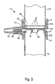
- a venting passageway 25 is formed at the interface 14 of the two holders and is in fluid communication with the upstream side of the membrane and provides a vent for the sample container 15 .
- venting passageway 25 is important to the proper operation of the vacuum filter device 10 because the sample container 15 is a closed vessel and the overall filter device is of liquid-tight construction.
- the venting passageway allows for maintaining the necessary pressure differential across the filter, a feature attributed to the previously described prior art because of the open nature of their feed containers at a sacrifice of the benefits of the liquid-tight system of the present embodiment, such as minimizing the risk of spills and contamination. While a closed sample container would be able to start the filtration process, it would not provide commercially acceptable performance over the course of filtration. To explain, the closed sample container starts the filtration process with an internal starting pressure at atmospheric pressure.
- the sample container needs to be maintained as close to P atmosphere as possible. With the present invention, this goal is achieved by the venting passageway connecting the sample container with the outside atmospheric pressure.
- the venting passageway as shown in Fig. 4A is formed in the filter body in a manner which creates a passageway whose smallest dimension is 0.381 mm (0.015 inches) or less. Details of the techniques used to create this small dimension passageway in the filter body 11 are best discussed with reference to Figs. 5A, B and C.
- the filter body is constructed by ultrasonically welding the two holders 12, 13 at the interface 14.
- a forming tool 50 is placed between the two holders prior to initiating the weld process. This tool can take a variety of shapes depending on the desired dimensions of the orifice.
- a circular wire of diameter 0.381 mm (0.015 inches) is used, although it will be understood that forms of rectangular cross-section or even other geometries may be employed.
- Fig. 5B shows the holders placed together with the forming tool in position as ultrasonic energy is applied. After the holders are welded together, the forming tool is removed leaving a through-hole whose dimensions correspond to that of the tool. To assist in the removal, the remote end of the forming tool can be slightly tapered such that as the minimum force required to begin disengaging the forming tool is applied the remainder of the tool will more readily be removed from the interface 14 between the two holders.
- Injection molding methods generally provide the greatest dimensional control of shape with plastic parts.
- conventional molding processing techniques would not allow a passageway that is molded into the wall of the holder 12 to be 0.381 mm (0.015 inches) or less. This is because as the molten plastic enters the mold cavity the pin used to create the passageway would deflect leading to fatigue and breakage. Also, for the pin to seal off against the other wall of the cavity, the sealing end of the pin will be peened over in time leading to flashing. Flashing is an uncontrollable, undesirable migration of plastic, which in this example will lead to filling and dimensionally distorting the venting passageway 25 .
- a forming tool during the joining process provides for a dimensionally controlled geometry that is independent of the molding process and controllable with a variety of joining processes in addition to the ultrasonic welding process of the embodiment described, such as vibration bonding, radiant heat and other fusion bonding processes as well as solvent bonding.
- venting passageway 25 with dimensions of 0.381 mm (0.015 inches) or less provides significant advantages in that the filtration device maintains its liquid-tight capabilities without employing an additional membrane covering the venting passageway to prevent solution from leaking out of the device during normal use.
- Fig. 4B shows the inclusion of a hydrophobic liner 44 positioned in the venting passageway 25 which serves as a hydrophobic porous matrix.
- Preferred forms of this matrix include porous hollow fiber membranes, porous polymer rods or micro-bore tubing, all constructed from a suitable hydrophobic resin.
- a molded slot of predetermined dimension and geometry sufficient to encapsulate the liner is formed in opposing surfaces 45, 46 of the respective holders 12, 13.
- the liner is then crimped in place without collapsing its lumen during the holder joining process to provide fluid communication between the sample container 15 and the outside atmospheric pressure.
- Use of a hydrophobic liner allows the materials of the filter body to be selected based on economics or specific material properties. As mentioned, the venting passageway need not be completely lined but only imparted with hydrophobic properties along a portion of the passageway.
- this attribute may be further enhanced by applying a hydrophobic treatment to the surfaces of the passageway, preferably in liquid form during assembly of the Fig. 4A embodiment.
- a hydrophobic solution such as polytetrafluoroethylene (PTFE) in suspension may be applied to the forming tool 50 before the tool is inserted between the holders 12, 13.
- PTFE polytetrafluoroethylene
- the hydrophobic liquid treatment decreases the surface energy and prevents leakage of the sample solution during normal laboratory use.
- a sample solution to be filtered is deposited in the sample container 15 and is screwed tightly onto the holder 12 with the open end of the sample container being held upward until the upper lip of the container is squeezed against the angled surface of the ring 22A. Tightly screwing the container to the filter body 11 creates a fluid-tight seal.
- the filtrate container 16 is screwed into the holder 13 against the angled surface of the ring 22B.
- the filtrate container and the filter body are pre-sterilized prior to coupling them together.
- the device 10 is then flipped over such that the sample container 15 is oriented upward with respect to the filter body 11 as shown in Fig. 1.
- a length of tubing 28 is connected to a vacuum pump (not shown) and a vacuum is applied to port 23 and the filtrate container is evacuated of air and the pressure therein correspondingly reduced.
- the unfiltered sample solution is then passed from the higher pressure sample container 15 through the membrane guard 20 and the membrane 18.
- the filtered solution flows through the opening 30 and collects as filtrate in the filtrate container 16.
- air at atmospheric pressure enters through the venting passageway 25 and replaces the volume of sample solution that passes through the membrane.
- the dimensions of the venting passageway discussed with respect to the embodiment shown in Fig 4A are so small that sample does not leak out from the sample container 15, thus preserving the liquid-tight nature of the filtration device.
Landscapes
- Engineering & Computer Science (AREA)
- Chemical & Material Sciences (AREA)
- Chemical Kinetics & Catalysis (AREA)
- Mechanical Engineering (AREA)
- Water Supply & Treatment (AREA)
- Health & Medical Sciences (AREA)
- Analytical Chemistry (AREA)
- General Health & Medical Sciences (AREA)
- Hematology (AREA)
- Clinical Laboratory Science (AREA)
- Manufacturing & Machinery (AREA)
- Separation Using Semi-Permeable Membranes (AREA)
- Sampling And Sample Adjustment (AREA)
Abstract
Claims (22)
- Un dispositif de filtrage à vide comprenant:un corps de filtre (11) comportant deux jonctions (12, 13) disposées l'une pour l'autre, chacune desdites jonctions (12, 13) étant adaptée pour recevoir une alimentation respective et des récipients à filtrat (15, 16);chacune desdites jonctions (12, 13) comprenant des moyens d'étanchéité (22A, 22B) pour créer un joint d'étanchéité étanche aux liquides lorsque lesdits récipients (15, 16) sont couplés audit corps de filtre (11), ledit récipient d'alimentation (15) servant à loger un liquide devant être filtré et ledit récipient à filtrat (16) servant à recevoir le liquide filtré, chacun desdits récipients (15, 16) formant des réceptacles étanches ou liquides, lorsqu'ils sont couplés audit corps de filtre (11);un filtre (18), enfermé de façon étanche à l'intérieur dudit corps de filtre (11) entre lesdites jonctions (12, 13), de manière que le liquide présent dans ledit récipient d'alimentation (15), du côté amont dudit filtre (18), doive passer à travers ledit filtre (18) pour aller au côté aval du filtre (18), avant de pénétrer dans ledit récipient à filtrat (16);un orifice à vide (23), s'étendant à travers ledit corps de filtre (11) et mis en communication fluidique avec ledit côté aval dudit filtre (18), ledit orifice à vide (23) étant adapté pour être relié à une source de vide pour extraire ledit liquide depuis ledit côté amont du filtre (18), à travers ledit filtre (18), et pour aller audit côté aval du filtre (18); etune voie de passage d'évent (25) formée dans ledit corps de filtre (11), mise en communication avec le côté amont dudit filtre (18) et avec l'atmosphère entourant ledit dispositif de filtrage sous vide (10), ladite voie de passage d'évent (25) étant dimensionnée de manière que le passage du liquide venant du côté amont du filtre vers l'atmosphère soit empêché pendant un usage normal, tandis que du gaz venant de l'atmosphère peut passer vers le côté amont du filtre (18).
- Le dispositif selon la revendication 1, dans lequel ladite voie de passage d'évent (25) s'étend à travers ledit corps de filtre (11), radialement vers l'intérieur depuis la périphérie dudit corps de filtre (11).
- Le dispositif selon la revendication 1 ou 2, dans lequel ladite voie de passage d'évent (25) est de section transversale circulaire et est d'un diamètre de 0,381 mm (0,015 pouce) ou moins.
- Le dispositif selon la revendication 1 ou 2, dans lequel ladite voie de passage d'évent (25) est de section transversale rectangulaire et la dimension minimale de ladite voie de passage est de 0,381 mm (0,015 pouce) ou moins.
- Le dispositif selon l'une quelconque des revendications 1 à 4, dans lequel ledit filtre (18) est une membrane microporeuse.
- Le dispositif selon l'une quelconque des revendications 1 à 4, dans lequel ledit filtre (18) est un filtre en profondeur.
- Le dispositif selon l'une quelconque des revendications 1 à 4, dans lequel ledit filtre (18) est une combinaison d'une membrane microporeuse et d'un filtre en profondeur.
- Le dispositif selon l'une quelconque des revendications 1 à 7, comprenant une matrice poreuse hydrophobe placée à l'intérieur de ladite voie de passage d'évent (25).
- Le dispositif selon l'une quelconque des revendications 1 à 7, comprenant un tube hydrophobe placé à l'intérieur de ladite voie de passage d'évent (25).
- Le dispositif selon l'une quelconque des revendications 1 à 7, dans lequel au moins une partie des surfaces de ladite voie de passage d'évent (25) est hydrophobe.
- Le dispositif selon l'une quelconque des revendications 1 à 10, dans lequel ledit corps de filtre (11) est de section transversale circulaire, lesdites jonctions sont des supports filetés (12, 13) disposés axialement l'un par rapport à l'autre et adaptés pour s'ajuster et venir en prise par des filets ménagés sur lesdits récipients d'alimentation et de filtrat (15, 16).
- Le dispositif selon la revendication 11, dans lequel lesdits moyens d'étanchéité comprennent un anneau annulaire levé (22A, 22B), adapté pour venir en prise avec lesdits récipients d'alimentation et de filtrat (15, 16), afin de former un montage par compression entre ledit anneau (22A, 22B) et une paroi desdits supports (12, 13), lorsque lesdits récipients d'alimentation et de filtrat (15, 16) sont vissés dans les filets desdits supports (12, 13).
- Le dispositif selon l'une quelconque des revendications 1 à 10, dans lequel lesdits moyens d'étanchéité comprennent un joint en élastomère, placé à l'intérieur d'une base desdits supports (12, 13).
- Le dispositif selon l'une quelconque des revendications 1 à 13, incluant une matrice de préfiltration disposée en amont dudit filtre (18).
- Un procédé de fabrication d'un dispositif de filtrage à vide, tel que défini selon l'une quelconque des revendications 1 à 14, comprenant les étapes consistant à :disposer lesdites deux jonctions (12, 13) l'une par rapport à l'autre, à l'interface (14) de celles-ci, ledit filtre (18) étant placé en position intermédiaire et enfermé de façon étanche dans l'une desdites jonctions (12, 13);insérer un outil de formage (50) à l'interface (14) entre lesdites jonctions (12, 13), avant de relier d'une seule pièce lesdites jonctions (12, 13), ledit outil (50) étant de dimensions et de section transversale correspondant à celles de ladite voie de passage d'évent (25), de préférence de section transversale circulaire ou rectangulaire d'un diamètre de 0,381 mm (0,015 pouce) ou moins, ou avec une dimension minimale de 0,381 mm (0,015 pouce) ou moins, respectivement;relier d'une seule pièce lesdites jonctions (12, 13) ensemble pour former ledit corps de filtre (11); etenlever ledit outil de formage (50) après avoir relié ensemble lesdites jonctions (12, 13).
- Le procédé selon la revendication 15, dans lequel ledit outil de formage (50) est effilé en au moins la zone insérée la première dans ladite interface (14), afin de faciliter l'enlèvement après que lesdites jonctions (12, 13) aient été reliées ensemble.
- Le procédé selon la revendication 15 ou 16, dans lequel les jonctions (12, 13) sont reliées par un processus sélectionné dans le groupe constitué du soudage par ultrasons, de la liaison par vibrations, de la fusion thermique et de la liaison par solvant.
- Le procédé selon la revendication 15, 16 ou 17, comprenant en outre l'étape additionnelle de transmettre des propriétés hydrophobes à la totalité ou à une partie de la voie de passage d'évent (25) formée lors de l'enlèvement de l'outil de formage (50) d'envers lesdites jonctions (12, 13).
- Le procédé selon la revendication 18, dans lequel les propriétés hydrophobes sont transmises par insertion d'une matrice poreuse hydrophobe, de préférence sélectionnée parmi le groupe constitué des membranes à fibres creuses, des tiges en polymère poreux et d'un tubage microporeux, à l'intérieur de la voie de passage d'évent (25).
- Le procédé selon la revendication 18, dans lequel les propriétés hydrophobes sont transmises par application d'un matériau liquide hydrophobe à l'intérieur de la voie de passage (25) et en le laissant sécher.
- Le procédé selon la revendication 20, dans lequel le matériau liquide hydrophobe est du polytétrafluoréthylène en suspension.
- Le procédé selon la revendication 21, dans lequel le polytétrafluoréthylène est appliqué à l'outil de formage (50) avant que cet outil de formage (50) soit inséré à l'interface (14) des deux jonctions (12, 13).
Priority Applications (1)
| Application Number | Priority Date | Filing Date | Title |
|---|---|---|---|
| EP00121976A EP1074292B1 (fr) | 1995-05-19 | 1996-05-16 | Dispositif de filtrage à vide |
Applications Claiming Priority (3)
| Application Number | Priority Date | Filing Date | Title |
|---|---|---|---|
| US444493 | 1995-05-19 | ||
| US08/444,493 US5603900A (en) | 1995-05-19 | 1995-05-19 | Vacuum filter device |
| PCT/US1996/007316 WO1996036428A1 (fr) | 1995-05-19 | 1996-05-16 | Dispositif de filtrage a vide et procede |
Related Child Applications (1)
| Application Number | Title | Priority Date | Filing Date |
|---|---|---|---|
| EP00121976.5 Division-Into | 2000-10-09 |
Publications (2)
| Publication Number | Publication Date |
|---|---|
| EP0873174A1 EP0873174A1 (fr) | 1998-10-28 |
| EP0873174B1 true EP0873174B1 (fr) | 2001-07-18 |
Family
ID=23765138
Family Applications (2)
| Application Number | Title | Priority Date | Filing Date |
|---|---|---|---|
| EP96920334A Expired - Lifetime EP0873174B1 (fr) | 1995-05-19 | 1996-05-16 | Dispositif de filtrage a vide et procede de fabrication d'un tel dispositif |
| EP00121976A Expired - Lifetime EP1074292B1 (fr) | 1995-05-19 | 1996-05-16 | Dispositif de filtrage à vide |
Family Applications After (1)
| Application Number | Title | Priority Date | Filing Date |
|---|---|---|---|
| EP00121976A Expired - Lifetime EP1074292B1 (fr) | 1995-05-19 | 1996-05-16 | Dispositif de filtrage à vide |
Country Status (5)
| Country | Link |
|---|---|
| US (3) | US5603900A (fr) |
| EP (2) | EP0873174B1 (fr) |
| DE (2) | DE69633029T2 (fr) |
| ES (2) | ES2220314T3 (fr) |
| WO (1) | WO1996036428A1 (fr) |
Families Citing this family (115)
| Publication number | Priority date | Publication date | Assignee | Title |
|---|---|---|---|---|
| GB9422504D0 (en) * | 1994-11-08 | 1995-01-04 | Robertson Patricia M B | Blood testing |
| US5603900A (en) * | 1995-05-19 | 1997-02-18 | Millipore Investment Holdings Limited | Vacuum filter device |
| JPH09196911A (ja) * | 1996-01-19 | 1997-07-31 | Fuji Photo Film Co Ltd | 血液濾過ユニット |
| US5725763A (en) * | 1996-06-24 | 1998-03-10 | Millipore Corporation | Vacuum filtration device sealable vacuum vent |
| US5957831A (en) * | 1996-07-12 | 1999-09-28 | Adair; Edwin L. | Sterile encapsulated endoscopic video monitor |
| US5882943A (en) * | 1996-07-31 | 1999-03-16 | Aldeen; William Erick | Filtration apparatus, kit and method for processing parasite samples |
| US5951864A (en) * | 1996-10-28 | 1999-09-14 | Emerson Electric Co. | Screening system |
| JP3685283B2 (ja) * | 1997-02-13 | 2005-08-17 | 富士写真フイルム株式会社 | 血漿採取具 |
| US6004822A (en) * | 1997-04-04 | 1999-12-21 | Alfred LaGreca | Device and method for measuring solubility and for performing titration studies of submilliliter quantities |
| US5925250A (en) * | 1997-12-30 | 1999-07-20 | Medical Chemical Corp. | Concentrator & Filter having protected end portion |
| EP0953842A1 (fr) * | 1998-05-01 | 1999-11-03 | F. Hoffmann-La Roche Ag | Analysateur automatique avec chambre de mélange amincie au dessous et unité de base liée étanchement à la chambre de mélange |
| US6187182B1 (en) * | 1998-07-31 | 2001-02-13 | Semifab Incorporated | Filter cartridge assembly for a gas purging system |
| US6896849B2 (en) * | 1998-10-29 | 2005-05-24 | Applera Corporation | Manually-operable multi-well microfiltration apparatus and method |
| US6906292B2 (en) * | 1998-10-29 | 2005-06-14 | Applera Corporation | Sample tray heater module |
| US6159368A (en) | 1998-10-29 | 2000-12-12 | The Perkin-Elmer Corporation | Multi-well microfiltration apparatus |
| DE19905645C1 (de) * | 1999-02-11 | 2000-10-26 | Sartorius Gmbh | Filteraufsatz zur Vakuumfiltration |
| US6458278B1 (en) * | 1999-02-22 | 2002-10-01 | Nalge Nunc International Corporation | Filtering unit having separately attachable filter cassette, filter cassette, and method of filtering |
| EP1034812B1 (fr) * | 1999-03-11 | 2006-05-10 | Medtronic, Inc. | Event hydrophobe incorporé dans une chambre de drainage de fluide cérébrospinal |
| US7108791B2 (en) * | 1999-09-14 | 2006-09-19 | Millipore Corporation | High-resolution virus removal methodology and filtration capsule useful therefor |
| FR2801660B1 (fr) * | 1999-11-29 | 2002-01-18 | Chemunex | Dispositif de manipulation d'un porte-support solide pour contaminants |
| CA2337987A1 (fr) | 2000-02-25 | 2001-08-25 | Elmex Limited | Systeme de filtration a membrane |
| US6446463B2 (en) * | 2000-03-09 | 2002-09-10 | S.K.G. Italiana S.P.A. | Filter cartridge and condenser |
| US6602414B2 (en) * | 2000-03-30 | 2003-08-05 | Formulations Pro | Molecule separation device and method combining multiple filtration media |
| US6749755B2 (en) | 2000-06-29 | 2004-06-15 | Robert S. Johnson | Water separation from solvent |
| EP1309391A4 (fr) * | 2000-06-29 | 2005-04-27 | Horizon Technology Inc | Separation d'une eau et d'un solvant |
| US20030191442A1 (en) * | 2000-08-11 | 2003-10-09 | The Procter & Gamble Company | Topsheet for contacting hydrous body tissues and absorbent device with such a topsheet |
| AU2441402A (en) * | 2000-10-18 | 2002-04-29 | Clarity Technologies Inc | Method and device for diluting a fluid and detecting analytes within a diluted fluid |
| US20020096468A1 (en) * | 2000-12-04 | 2002-07-25 | Peter Zuk | Disposable vacuum filtration apparatus capable of detecting microorganisms and particulates in liquid samples |
| JP3787520B2 (ja) * | 2000-12-28 | 2006-06-21 | キヤノン株式会社 | 構造体の製造方法およびその製造装置 |
| US6491873B2 (en) * | 2001-01-23 | 2002-12-10 | Varian, Inc. | Multi-well filtration apparatus |
| US6360595B1 (en) | 2001-03-16 | 2002-03-26 | Ethicon Endo-Surgery, Inc. | Liquid measuring device and method of using |
| US7266085B2 (en) * | 2001-03-21 | 2007-09-04 | Stine John A | Access and routing protocol for ad hoc network using synchronous collision resolution and node state dissemination |
| US7661538B1 (en) | 2001-05-31 | 2010-02-16 | Roush Life Science, LLC | Disposable vacuum filtration funnel with integral prefilter |
| US7011755B2 (en) * | 2001-05-31 | 2006-03-14 | Zuk Jr Peter | Disposable vacuum filtration funnel with integral prefilter |
| JP4370552B2 (ja) * | 2001-09-14 | 2009-11-25 | ニプロ株式会社 | 薬液注入ポート |
| US6780309B2 (en) * | 2002-03-22 | 2004-08-24 | Allegiance Corporation | Tapered hydrophobic filter for suction canisters |
| US7176034B2 (en) * | 2002-07-03 | 2007-02-13 | St. Joseph's Healthcare | Apparatus and method for filtering biological samples |
| US7122155B2 (en) * | 2002-07-16 | 2006-10-17 | Mcgill University | Electron microscopy cell fraction sample preparation robot |
| US7214348B2 (en) * | 2002-07-26 | 2007-05-08 | Applera Corporation | Microfluidic size-exclusion devices, systems, and methods |
| CA2492613A1 (fr) * | 2002-07-26 | 2004-02-05 | Applera Corporation | Dispositifs, systemes et procedes d'exclusion de taille microfluidique |
| US6884341B2 (en) * | 2002-10-02 | 2005-04-26 | G6 Science Corp. | Filter device to capture a desired amount of material |
| US6905594B2 (en) * | 2002-10-11 | 2005-06-14 | G6 Science Corp. | Filter apparatus and methods to capture a desired amount of material from a sample suspension for monolayer deposition, analysis or other uses |
| WO2004071629A1 (fr) * | 2003-02-12 | 2004-08-26 | Millipore Corporation | Dispositif de filtration sous vide |
| WO2005003346A1 (fr) * | 2003-06-06 | 2005-01-13 | Applera Corporation | Dispositif de purification d'acide ribonucleique en larges volumes, et procede associe |
| EP1491258B1 (fr) * | 2003-06-24 | 2008-12-03 | Millipore Corporation | Systeme de vide multifonctionnelle |
| US7824623B2 (en) | 2003-06-24 | 2010-11-02 | Millipore Corporation | Multifunctional vacuum manifold |
| JP4144874B2 (ja) * | 2003-09-30 | 2008-09-03 | 富士フイルム株式会社 | 生化学解析用ユニットを用いた反応方法 |
| US7614203B2 (en) * | 2004-01-13 | 2009-11-10 | Safety Solutions, Inc. | User installable vacuum seal apparatus for storage bags |
| US20050236318A1 (en) * | 2004-04-23 | 2005-10-27 | Millipore Corporation | Low holdup volume multiwell plate |
| US20060074345A1 (en) * | 2004-09-29 | 2006-04-06 | Hibner John A | Biopsy apparatus and method |
| NO20050910A (no) * | 2005-02-21 | 2006-05-02 | Norconserv As | Anordning og fremgangsmåte for analyse av næringsmiddel ved hjelp av en prøvekopp |
| US7867173B2 (en) | 2005-08-05 | 2011-01-11 | Devicor Medical Products, Inc. | Biopsy device with replaceable probe and incorporating vibration insertion assist and static vacuum source sample stacking retrieval |
| USRE46135E1 (en) | 2005-08-05 | 2016-09-06 | Devicor Medical Products, Inc. | Vacuum syringe assisted biopsy device |
| US7854707B2 (en) | 2005-08-05 | 2010-12-21 | Devicor Medical Products, Inc. | Tissue sample revolver drum biopsy device |
| WO2007028157A1 (fr) * | 2005-09-02 | 2007-03-08 | Zuk Peter Jr | Systemes, appareils et procedes de filtration sous vide |
| US8747669B1 (en) | 2005-12-29 | 2014-06-10 | Spf Innovations, Llc | Method and apparatus for the filtration of biological samples |
| US7384549B2 (en) * | 2005-12-29 | 2008-06-10 | Spf Innovations, Llc | Method and apparatus for the filtration of biological solutions |
| WO2007130991A1 (fr) * | 2006-05-01 | 2007-11-15 | Horizon Technology Inc. | Système et procédé de prélèvement d'échantillon |
| TW200800747A (en) * | 2006-06-15 | 2008-01-01 | Antera Biotech Corp | Generating box of a reagent |
| EP1908872A1 (fr) * | 2006-10-02 | 2008-04-09 | Falmer Investments Limited | soufflante pour une machine de traitment de textiles |
| US20140039343A1 (en) | 2006-12-13 | 2014-02-06 | Devicor Medical Products, Inc. | Biopsy system |
| US8702623B2 (en) * | 2008-12-18 | 2014-04-22 | Devicor Medical Products, Inc. | Biopsy device with discrete tissue chambers |
| US9345457B2 (en) | 2006-12-13 | 2016-05-24 | Devicor Medical Products, Inc. | Presentation of biopsy sample by biopsy device |
| CA2574322C (fr) * | 2007-01-18 | 2012-08-28 | Scp Science | Cartouche reversible de filtre a vide |
| WO2008144083A1 (fr) * | 2007-05-23 | 2008-11-27 | Nypro Inc. | Procédés et appareil destinés au contrôle de la mousse dans un système de filtration sous vide |
| EP2158137A4 (fr) * | 2007-06-07 | 2012-01-18 | Andrew Gadzic | Système de bouchon et de revêtement pour un contenant |
| US8231012B2 (en) * | 2007-07-26 | 2012-07-31 | Roush Life Sciences, Llc | Filtrate storage system |
| US8235221B2 (en) * | 2007-07-26 | 2012-08-07 | Roush Life Sciences, Llc | Methods for vacuum filtration |
| EP2200729B1 (fr) | 2007-10-04 | 2012-06-20 | EMD Millipore Corporation | Dispositif de filtration |
| US8863594B2 (en) | 2008-02-22 | 2014-10-21 | Foxx Life Sciences | Sample container and filtration apparatus and method of filtration using same |
| US20090215150A1 (en) * | 2008-02-22 | 2009-08-27 | Jeffrey Kane | Sample container and filtration apparatus and method of filtration using the same |
| FR2928526B1 (fr) * | 2008-03-14 | 2012-12-28 | Eurocave Sa | Armoire de conservation de bouteilles, en particulier de bouteilles de vin. |
| WO2010102632A2 (fr) * | 2009-03-12 | 2010-09-16 | Rigshospitalet | Procédé perfectionné de purification d'arn |
| US8105843B2 (en) * | 2009-11-04 | 2012-01-31 | Buchanan Thomas M | Methods and devices to enhance sensitivity and evaluate sample adequacy and reagent reactivity in rapid lateral flow immunoassays |
| DE102010001322A1 (de) * | 2010-01-28 | 2011-08-18 | Siemens Aktiengesellschaft, 80333 | Anordnung und Verfahren zur Filtration einer Flüssigkeit und Verwendung in der Mikroskopie |
| US9220485B2 (en) | 2010-08-28 | 2015-12-29 | Endochoice, Inc. | Tissue collection and separation device |
| US8808552B2 (en) * | 2010-12-16 | 2014-08-19 | Zenpure (Hangzhou) Co., Ltd. | Stackable filter cup apparatus and method |
| EP2758096A4 (fr) | 2011-09-21 | 2015-07-01 | Bayer Medical Care Inc | Système et procédé de distribution multi-fluide continue |
| FR2986976B1 (fr) * | 2012-02-17 | 2015-06-19 | Cummins Filtration Sarl | Cartouche de filtration integrant un element permeable au gaz dans le flasque superieur |
| US20130264286A1 (en) * | 2012-04-06 | 2013-10-10 | Cells Scientific Corporation | Biological sample filtering system and method for filtering biological samples |
| CN102847932A (zh) * | 2012-04-07 | 2013-01-02 | 郴州市金贵银业股份有限公司 | 一种金属粉末的清洗装置 |
| CN104203530B (zh) * | 2012-04-19 | 2016-02-24 | 东海兴业株式会社 | 复合成型体和用于制造该复合成型体的方法 |
| US9709500B2 (en) | 2012-05-02 | 2017-07-18 | Charles River Laboratories, Inc. | Optical method for detecting viable microorganisms in a cell sample |
| CN104662425B (zh) | 2012-05-02 | 2017-10-10 | 查尔斯河实验室公司 | 活性染色方法 |
| EP2769204B1 (fr) * | 2012-05-02 | 2016-02-17 | Charles River Laboratories, Inc. | Système de capture cellulaire et son utilisation |
| ITFI20130016A1 (it) * | 2013-01-21 | 2014-07-22 | Aautomag S R L | "contenitore per elementi filtranti, dispositivo impiegante detto contenitore e metodo di microfiltrazione" |
| USD704383S1 (en) * | 2013-02-07 | 2014-05-06 | Anna M. Edlin | Pet travel cup with internal spiral member and rimmed edge |
| JP6502354B2 (ja) * | 2013-09-05 | 2019-04-17 | メルク パテント ゲゼルシャフト ミット ベシュレンクテル ハフツングMerck Patent Gesellschaft mit beschraenkter Haftung | 複合流体サンプルを濾過するためのフィルタデバイス |
| JP6556155B2 (ja) | 2013-11-04 | 2019-08-07 | チャールズ リバー ラボラトリーズ, インコーポレイテッド | ろ過システム及びその用途 |
| DE102013019807B4 (de) * | 2013-11-26 | 2023-07-20 | Hydac Filtertechnik Gmbh | Filtervorrichtung und Filterelement |
| US10278534B2 (en) * | 2013-12-01 | 2019-05-07 | Fellow Industries Inc. | Beverage steeping and dispensing system |
| EP3077505A4 (fr) | 2013-12-04 | 2018-01-24 | Pocared Diagnostics Ltd | Procédé et appareil permettant de traiter et analyser des particules issues d'une filtration tangentielle |
| US10399077B2 (en) * | 2014-03-17 | 2019-09-03 | Daniel Rego | Dual flask |
| US9850040B2 (en) * | 2014-03-21 | 2017-12-26 | Emd Millipore Corporation | Container and container engaging member suitable for vacuum assisted filtration |
| US20170225161A1 (en) * | 2014-08-15 | 2017-08-10 | California Institute Of Technology | The pumping lid: devices and methods for programmable generation of positive and negative pressures |
| RU2714926C2 (ru) | 2015-01-09 | 2020-02-21 | БАЙЕР ХелсКер ЛЛСи | Многофлюидная система доставки с многоразовым расходным комплектом и ее конструкционные особенности |
| WO2016166673A1 (fr) * | 2015-04-16 | 2016-10-20 | Gupta Nalini K | Système de filtration sous vide |
| EP3386561B1 (fr) | 2015-12-11 | 2023-05-03 | NxStage Medical, Inc. | Systèmes , procédés et dispositifs de raccord pour ligne de fluide |
| CN105647784A (zh) * | 2016-03-08 | 2016-06-08 | 闫维新 | 一种基于负压的特异细胞处理装置 |
| SG11201901134RA (en) | 2016-10-17 | 2019-03-28 | Emd Millipore Corp | Device suitable for vacuum assisted filtration |
| JP6802371B2 (ja) | 2016-10-20 | 2020-12-16 | イー・エム・デイー・ミリポア・コーポレイシヨン | バルブ保護およびチューブ管理装置 |
| US11612888B2 (en) | 2017-01-04 | 2023-03-28 | The Research Foundation For The State University Of New York | Biomarker detection device |
| JP6956203B2 (ja) | 2017-05-10 | 2021-11-02 | イー・エム・デイー・ミリポア・コーポレイシヨン | 可変圧縮封止部を備えるマルチウェル板 |
| CA3070832A1 (fr) | 2017-08-02 | 2019-02-07 | Pocared Diagnostics Ltd. | Agencement de filtre de processeur qui comprend un procede et un appareil pour eliminer un fluide residuaire a travers un filtre |
| SG11202001840RA (en) * | 2017-09-06 | 2020-03-30 | Merck Patent Gmbh | Filtration assembly and method for microbiological testing |
| DE102017127970B3 (de) | 2017-11-27 | 2019-01-10 | Sartorius Stedim Biotech Gmbh | Filtrationsbasis für Vakuum-Membranfiltration und eine Filtrationsvorrichtung |
| DE102017127969B3 (de) | 2017-11-27 | 2019-01-17 | Sartorius Stedim Biotech Gmbh | Anschlusseinrichtung für eine Absaugvorrichtung |
| KR102071046B1 (ko) * | 2018-02-05 | 2020-01-28 | 주식회사 이노디자인 | 드립핑 용기 및 휴대용 커피 음용 용기 |
| CN108579155B (zh) * | 2018-07-06 | 2024-04-23 | 中国疾病预防控制中心环境与健康相关产品安全所 | 用于两虫染色的过滤装置 |
| US11806642B2 (en) | 2018-08-31 | 2023-11-07 | FUJIFILM Irvine Scientific, Inc. | Venting system for a mixing apparatus |
| CN109847816A (zh) * | 2019-01-03 | 2019-06-07 | 温州医科大学 | 一种微流控分离芯片 |
| JP7560465B2 (ja) * | 2019-01-16 | 2024-10-02 | メルク パテント ゲゼルシャフト ミット ベシュレンクテル ハフツング | 真空濾過用濾過ヘッド、真空濾過用マニホールド、および、既存の真空濾過用濾過ヘッドの改造方法 |
| JP7359632B2 (ja) * | 2019-10-11 | 2023-10-11 | 株式会社日立ハイテク | 細菌叢捕集装置及び細菌叢捕集方法 |
| KR102167104B1 (ko) * | 2020-01-30 | 2020-10-16 | 주식회사 에스티원 | 투과막의 탈부착이 가능한 투과막 서포트 |
| US12011692B2 (en) * | 2021-07-19 | 2024-06-18 | Spf Technologies Llc | Separation device |
Family Cites Families (24)
| Publication number | Priority date | Publication date | Assignee | Title |
|---|---|---|---|---|
| US3844895A (en) * | 1972-01-03 | 1974-10-29 | Millipore Corp | Filtration and incubation apparatus |
| US4251366A (en) * | 1979-06-18 | 1981-02-17 | Simon Timothy M | Adapter for laboratory filter |
| US4301010A (en) * | 1980-03-10 | 1981-11-17 | Spectrum Medical Industries, Inc. | Vacuum filter |
| AT377228B (de) * | 1980-07-24 | 1985-02-25 | Lignotock Verfahrenstech | Verfahren und vorrichtung zum herstellen von formteilen aus ebenen wirrfaservliesmatten, vorzugsweise aus mit bindemittel versehenen zellulose-oder lignozellulosefasern |
| US4357240A (en) * | 1981-02-27 | 1982-11-02 | Sybron Corporation | Disposable, one-piece filter unit |
| DE3169275D1 (en) * | 1981-03-02 | 1985-04-18 | Sybron Corp | Disposable filtration unit with recoverable filter |
| CA1198063A (fr) * | 1981-09-16 | 1985-12-17 | Richard A. Leoncavallo | Filtre reutilisable a membrane filtrante recuperable |
| DE3201248A1 (de) * | 1982-01-16 | 1983-07-28 | M. Lehmacher & Sohn Gmbh Maschinenfabrik, 5216 Niederkassel | Vorrichtung zum querschweissen und trennen einer kunststoffolien-doppelbahn |
| US4673501A (en) * | 1985-11-19 | 1987-06-16 | Miles Laboratories, Inc. | Bottle top filter |
| US4702834A (en) * | 1986-06-17 | 1987-10-27 | Nalge Company | Plastic filter units having a weld cellulose filter |
| US4783318A (en) * | 1987-10-02 | 1988-11-08 | The State Of Minnesota | Apparatus for environmental leaching testing |
| FI82635C (sv) * | 1988-08-23 | 1991-04-10 | Muotekno Ab Oy | Förfarande och anordning för sammanfogning av rörformiga plastprodukt er |
| US4944876A (en) * | 1989-10-03 | 1990-07-31 | Telectro-Mek, Inc. | Filter capsule with inlet dispersion |
| US5110557A (en) * | 1990-07-09 | 1992-05-05 | Brown Bradley V | Blood sample collection apparatus |
| US5141639A (en) * | 1990-08-14 | 1992-08-25 | Gelman Sciences, Inc. | Vacuum filter assembly |
| US5209800A (en) * | 1990-08-20 | 1993-05-11 | Denco, Inc. | Total containment welding of plastic tubes |
| US5264184A (en) * | 1991-03-19 | 1993-11-23 | Minnesota Mining And Manufacturing Company | Device and a method for separating liquid samples |
| EP0612403B1 (fr) * | 1991-11-14 | 1999-02-03 | Artchem, Inc. | Systeme de raccordement et microtube |
| US5234585A (en) * | 1991-12-19 | 1993-08-10 | Zuk, Incorporated | Vacuum filtration device |
| US5265184A (en) * | 1992-05-28 | 1993-11-23 | Motorola, Inc. | Molded waveguide and method for making same |
| US5348798A (en) * | 1992-10-30 | 1994-09-20 | Azdel, Inc. | Method of making a hollow core structural member |
| US5375477A (en) * | 1993-01-04 | 1994-12-27 | S.P. Industries, Limited Partnership | Water impurity extraction device and method |
| DE4321927C2 (de) * | 1993-07-01 | 1998-07-09 | Sartorius Gmbh | Filtereinheit mit Entgasungsvorrichtung |
| US5603900A (en) * | 1995-05-19 | 1997-02-18 | Millipore Investment Holdings Limited | Vacuum filter device |
-
1995
- 1995-05-19 US US08/444,493 patent/US5603900A/en not_active Expired - Lifetime
-
1996
- 1996-05-16 WO PCT/US1996/007316 patent/WO1996036428A1/fr active IP Right Grant
- 1996-05-16 EP EP96920334A patent/EP0873174B1/fr not_active Expired - Lifetime
- 1996-05-16 DE DE69633029T patent/DE69633029T2/de not_active Expired - Lifetime
- 1996-05-16 ES ES00121976T patent/ES2220314T3/es not_active Expired - Lifetime
- 1996-05-16 ES ES96920334T patent/ES2159359T3/es not_active Expired - Lifetime
- 1996-05-16 EP EP00121976A patent/EP1074292B1/fr not_active Expired - Lifetime
- 1996-05-16 DE DE69614001T patent/DE69614001T2/de not_active Expired - Lifetime
- 1996-10-29 US US08/739,265 patent/US5792425A/en not_active Expired - Lifetime
-
1997
- 1997-03-24 US US08/823,255 patent/US5873967A/en not_active Expired - Lifetime
Also Published As
| Publication number | Publication date |
|---|---|
| US5873967A (en) | 1999-02-23 |
| US5792425A (en) | 1998-08-11 |
| DE69614001D1 (de) | 2001-08-23 |
| EP1074292A1 (fr) | 2001-02-07 |
| US5603900A (en) | 1997-02-18 |
| ES2220314T3 (es) | 2004-12-16 |
| ES2159359T3 (es) | 2001-10-01 |
| EP1074292B1 (fr) | 2004-07-28 |
| WO1996036428A1 (fr) | 1996-11-21 |
| EP0873174A1 (fr) | 1998-10-28 |
| DE69614001T2 (de) | 2002-03-14 |
| EP1074292A8 (fr) | 2001-06-06 |
| DE69633029D1 (de) | 2004-09-02 |
| DE69633029T2 (de) | 2005-07-21 |
Similar Documents
| Publication | Publication Date | Title |
|---|---|---|
| EP0873174B1 (fr) | Dispositif de filtrage a vide et procede de fabrication d'un tel dispositif | |
| CN101312785B (zh) | 用于真空过滤的系统、设备和方法 | |
| EP0059284B1 (fr) | Elément de filtre jetable en une seule pièce et le procédé de fabrication de celui-ci | |
| EP2574326B1 (fr) | Flacon filtrant doté d'un piston tubulaire, d'une coupelle de retenue et d'un filtre | |
| EP2200729B1 (fr) | Dispositif de filtration | |
| CA2298891C (fr) | Unite de filtrage avec cassette filtrante amovible separee, et methode de filtrage | |
| US20240226811A1 (en) | Device suitable for vacuum assisted filtration | |
| JP2009506886A5 (fr) | ||
| JPH09234351A (ja) | 濾液を流すための濾液導管を区切るチューブ | |
| US4473094A (en) | Air inlet | |
| GB2043478A (en) | Filter device | |
| US4234095A (en) | Collection container for sterile liquids | |
| JPH0412949B2 (fr) | ||
| EP3747527B1 (fr) | Capsule filtrante et procédé d'utilisation | |
| JPH10211403A (ja) | フィルタアセンブリ | |
| US4339334A (en) | Tubular membrane separation apparatus end joint seal |
Legal Events
| Date | Code | Title | Description |
|---|---|---|---|
| PUAI | Public reference made under article 153(3) epc to a published international application that has entered the european phase |
Free format text: ORIGINAL CODE: 0009012 |
|
| 17P | Request for examination filed |
Effective date: 19980212 |
|
| AK | Designated contracting states |
Kind code of ref document: A1 Designated state(s): DE ES FR GB IT |
|
| RBV | Designated contracting states (corrected) |
Designated state(s): DE ES FR GB IT |
|
| 17Q | First examination report despatched |
Effective date: 19991018 |
|
| GRAG | Despatch of communication of intention to grant |
Free format text: ORIGINAL CODE: EPIDOS AGRA |
|
| RTI1 | Title (correction) |
Free format text: VACUUM FILTER DEVICE AND METHOD OF MANUFACTURING SUCH DEVICE |
|
| GRAG | Despatch of communication of intention to grant |
Free format text: ORIGINAL CODE: EPIDOS AGRA |
|
| GRAH | Despatch of communication of intention to grant a patent |
Free format text: ORIGINAL CODE: EPIDOS IGRA |
|
| GRAH | Despatch of communication of intention to grant a patent |
Free format text: ORIGINAL CODE: EPIDOS IGRA |
|
| RAP1 | Party data changed (applicant data changed or rights of an application transferred) |
Owner name: MILLIPORE CORPORATION |
|
| GRAA | (expected) grant |
Free format text: ORIGINAL CODE: 0009210 |
|
| AK | Designated contracting states |
Kind code of ref document: B1 Designated state(s): DE ES FR GB IT |
|
| REF | Corresponds to: |
Ref document number: 69614001 Country of ref document: DE Date of ref document: 20010823 |
|
| REG | Reference to a national code |
Ref country code: ES Ref legal event code: FG2A Ref document number: 2159359 Country of ref document: ES Kind code of ref document: T3 |
|
| ITF | It: translation for a ep patent filed | ||
| ET | Fr: translation filed | ||
| REG | Reference to a national code |
Ref country code: GB Ref legal event code: IF02 |
|
| PG25 | Lapsed in a contracting state [announced via postgrant information from national office to epo] |
Ref country code: ES Free format text: LAPSE BECAUSE OF NON-PAYMENT OF DUE FEES Effective date: 20020517 |
|
| PLBE | No opposition filed within time limit |
Free format text: ORIGINAL CODE: 0009261 |
|
| STAA | Information on the status of an ep patent application or granted ep patent |
Free format text: STATUS: NO OPPOSITION FILED WITHIN TIME LIMIT |
|
| 26N | No opposition filed | ||
| REG | Reference to a national code |
Ref country code: ES Ref legal event code: FD2A Effective date: 20030611 |
|
| PG25 | Lapsed in a contracting state [announced via postgrant information from national office to epo] |
Ref country code: IT Free format text: LAPSE BECAUSE OF NON-PAYMENT OF DUE FEES Effective date: 20050516 |
|
| REG | Reference to a national code |
Ref country code: FR Ref legal event code: CD Owner name: EMD MILLIPORE CORPORATION Effective date: 20120327 |
|
| REG | Reference to a national code |
Ref country code: DE Ref legal event code: R082 Ref document number: 69614001 Country of ref document: DE Representative=s name: HENKEL, BREUER & PARTNER, DE |
|
| REG | Reference to a national code |
Ref country code: DE Ref legal event code: R082 Ref document number: 69614001 Country of ref document: DE Representative=s name: PATENTANWAELTE HENKEL, BREUER & PARTNER, DE Effective date: 20120613 Ref country code: DE Ref legal event code: R081 Ref document number: 69614001 Country of ref document: DE Owner name: EMD MILLIPORE CORPORATION, BILLERICA, US Free format text: FORMER OWNER: MILLIPORE CORP., BEDFORD, MASS., US Effective date: 20120613 Ref country code: DE Ref legal event code: R081 Ref document number: 69614001 Country of ref document: DE Owner name: EMD MILLIPORE CORPORATION, US Free format text: FORMER OWNER: MILLIPORE CORP., BEDFORD, US Effective date: 20120613 |
|
| REG | Reference to a national code |
Ref country code: FR Ref legal event code: PLFP Year of fee payment: 20 |
|
| PGFP | Annual fee paid to national office [announced via postgrant information from national office to epo] |
Ref country code: DE Payment date: 20150512 Year of fee payment: 20 Ref country code: GB Payment date: 20150513 Year of fee payment: 20 |
|
| PGFP | Annual fee paid to national office [announced via postgrant information from national office to epo] |
Ref country code: FR Payment date: 20150508 Year of fee payment: 20 |
|
| REG | Reference to a national code |
Ref country code: DE Ref legal event code: R071 Ref document number: 69614001 Country of ref document: DE |
|
| REG | Reference to a national code |
Ref country code: GB Ref legal event code: PE20 Expiry date: 20160515 |
|
| PG25 | Lapsed in a contracting state [announced via postgrant information from national office to epo] |
Ref country code: GB Free format text: LAPSE BECAUSE OF EXPIRATION OF PROTECTION Effective date: 20160515 |