EP0953842A1 - Analysateur automatique avec chambre de mélange amincie au dessous et unité de base liée étanchement à la chambre de mélange - Google Patents
Analysateur automatique avec chambre de mélange amincie au dessous et unité de base liée étanchement à la chambre de mélange Download PDFInfo
- Publication number
- EP0953842A1 EP0953842A1 EP19980810393 EP98810393A EP0953842A1 EP 0953842 A1 EP0953842 A1 EP 0953842A1 EP 19980810393 EP19980810393 EP 19980810393 EP 98810393 A EP98810393 A EP 98810393A EP 0953842 A1 EP0953842 A1 EP 0953842A1
- Authority
- EP
- European Patent Office
- Prior art keywords
- mixing chamber
- outlet opening
- unit
- automatic analyzer
- analyzer according
- Prior art date
- Legal status (The legal status is an assumption and is not a legal conclusion. Google has not performed a legal analysis and makes no representation as to the accuracy of the status listed.)
- Withdrawn
Links
Images


Classifications
-
- G—PHYSICS
- G01—MEASURING; TESTING
- G01N—INVESTIGATING OR ANALYSING MATERIALS BY DETERMINING THEIR CHEMICAL OR PHYSICAL PROPERTIES
- G01N1/00—Sampling; Preparing specimens for investigation
- G01N1/28—Preparing specimens for investigation including physical details of (bio-)chemical methods covered elsewhere, e.g. G01N33/50, C12Q
- G01N1/38—Diluting, dispersing or mixing samples
-
- B—PERFORMING OPERATIONS; TRANSPORTING
- B01—PHYSICAL OR CHEMICAL PROCESSES OR APPARATUS IN GENERAL
- B01L—CHEMICAL OR PHYSICAL LABORATORY APPARATUS FOR GENERAL USE
- B01L3/00—Containers or dishes for laboratory use, e.g. laboratory glassware; Droppers
- B01L3/56—Labware specially adapted for transferring fluids
- B01L3/569—Glassware
-
- G—PHYSICS
- G01—MEASURING; TESTING
- G01N—INVESTIGATING OR ANALYSING MATERIALS BY DETERMINING THEIR CHEMICAL OR PHYSICAL PROPERTIES
- G01N35/00—Automatic analysis not limited to methods or materials provided for in any single one of groups G01N1/00 - G01N33/00; Handling materials therefor
-
- G—PHYSICS
- G01—MEASURING; TESTING
- G01N—INVESTIGATING OR ANALYSING MATERIALS BY DETERMINING THEIR CHEMICAL OR PHYSICAL PROPERTIES
- G01N35/00—Automatic analysis not limited to methods or materials provided for in any single one of groups G01N1/00 - G01N33/00; Handling materials therefor
- G01N2035/00465—Separating and mixing arrangements
- G01N2035/00534—Mixing by a special element, e.g. stirrer
- G01N2035/00544—Mixing by a special element, e.g. stirrer using fluid flow
-
- Y—GENERAL TAGGING OF NEW TECHNOLOGICAL DEVELOPMENTS; GENERAL TAGGING OF CROSS-SECTIONAL TECHNOLOGIES SPANNING OVER SEVERAL SECTIONS OF THE IPC; TECHNICAL SUBJECTS COVERED BY FORMER USPC CROSS-REFERENCE ART COLLECTIONS [XRACs] AND DIGESTS
- Y10—TECHNICAL SUBJECTS COVERED BY FORMER USPC
- Y10T—TECHNICAL SUBJECTS COVERED BY FORMER US CLASSIFICATION
- Y10T436/00—Chemistry: analytical and immunological testing
- Y10T436/25—Chemistry: analytical and immunological testing including sample preparation
- Y10T436/2575—Volumetric liquid transfer
Definitions
- the invention relates to an automatic analyzer for Examination of liquid samples according to the generic term of claim 1.
- FIG. 1 shows, as prior art, the example of a block diagram of an automatic analyzer 10 for the selective determination of ions, for example Li + , K + , Na + ⁇ Cl - , in liquid samples of biological substances such as blood or urine.
- the samples are provided in separate vessels on a sample platform 11.
- an automatic pipette arm 12 small sample quantities can now be fed to a mixing chamber 14 in series.
- the chamber 14 is essentially a cylindrical vessel which is open at the top and has a continuously tapering bottom. In this vessel, inlet openings 15, 16 for air or water open at the top and two outlet openings 17, 20 at the bottom.
- the liquid samples arriving via the pipette needle can be homogenized by an air vortex generated via the opening 15 and via the outlet opening 20 and a connecting line 21 Feed measuring channel of an analysis block 22, which may be an electrode block, for example.
- the second inlet opening 16 is used primarily for supplying washing water and the outlet opening 17 for suctioning off the same and any excess liquid (waste).
- the measuring channel of the analysis block 22 is e.g. several Ion-selective electrodes and a reference electrode connected, the ion concentration z. B. the above measure the ions mentioned and via evaluation electronics 24 output the measurement results. The test liquid will finally for disposal in a collecting container 25 pushed out.
- the mixing chamber is easy to replace, so that an impairment of the Operability of the analyzer on a through a particle, e.g. a clot, clogged mixing chamber can be eliminated easily and quickly can.
- inventive Training the mixing chamber a quick and effective Cleaning, so that any in their outlet channel contained particles can be easily removed.
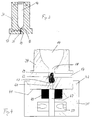
- FIG 2 shows a perspective view Mixing chamber unit 34 and an associated base unit 35.
- the mixing chamber unit 34 essentially has one cylindrical outer wall 36, to which a Bottom plate 37 with a larger diameter seamless connects. 37 laterally protrudes from this plate in shape a connection nipple out the first outlet opening 17, to which a waste water hose can be connected.
- the Mixing chamber unit 34 is open at the top (sample opening 38) and has a flat floor. This leads to - in the Representation hidden, but can be seen from Figure 1 - the Outlet opening 17. Two further go from this floor Risers into the wall 36 of the mixing chamber unit 34 up, which then in the known from Figure 1 Inlet openings 15, 16 open out.
- the base unit is the counterpart of the automatic analyzer 10 to the mixing chamber unit 34.
- the base unit 35 has accordingly a flat bottom 41 which is cylindrical from a guide cylinder 42 is surrounded, in which the Base plate 37 can be inserted flush.
- In the Guide cylinders 42 are an incision 43 for receiving the Outlet opening 17 and three locking slots 44.1, 44.2, 44.3 inserted.
- the connection 45 ends Riser for air, connection 46 of the riser for Water and the connection 47 of the second outlet opening 20 for the liquid to be analyzed;
- a spigot 48 provided, together with a not shown Blind hole in the base plate 37 for angular guidance the mixing chamber unit 34 when inserted into the Base unit 35 is used.
- connections 45, 46, 47 are preferred with ( replaceable) sealing rings 49 (Fig. 4) provided a tight connection with the openings 15, 16 and 20 guarantee.
- a union ring not shown, which can be pushed from above over the mixing chamber unit 34 which detects the upper edge of the bottom plate 37, and the by means of internally arranged pins which in the Interlock locking slots 44.1, 44.2, 44.3 and one Clockwise rotation is fixable.
- FIG 3 shows a central section through the Mixing chamber unit 34, approximately in the size ratio 2: 1 to Reality.
- the mixing chamber 14 is open at the top cylindrical design with as smooth a wall surface as possible, which tapers downwards, for example conical.
- the Wall of the mixing chamber has tip 18 at the bottom the mixing chamber 14 has an outlet opening 18 to which a connects vertical bore 19, the diameter or clear width about that of the connecting line 21 and of the measuring channel of the analysis block 22 corresponds.
- This vertical bore 19 is the first horizontally Outlet opening 17 connected.
- Below the bore 19 sets this as a second outlet opening 20 with one at a Transition (13) abruptly reduced diameter, whereby the reduced diameter, for example, still a third of the diameter of the bore 19 is.
- Practical values are, for example, 0.3-0.4 mm for the outlet opening 20 and 0.8 mm for the bore 19.
- the constriction 13 of the Outlet opening 20 serves as a trap for particles that are suitable are the blockages described at the beginning to evoke.
- Figure 4 shows an additional enlargement Section through the mixing chamber unit 34 and the Base unit 35.
- a particle 23 is shown, to which the Continuing in the direction of the connection 47 is prohibited. This particle 23 reduces or blocks the desired one Flow of the measuring liquid to be analyzed to Analysis block 22.
- Such a state can in each case detected by a fluid sensor 50 at the connection 47, which registers the absence of the expected liquid. In such a case, the automatic analyzer can then be stopped.
- the fluid sensor 50 serves as a safer Detector for any necessary replacement and cleaning the mixing chamber unit. Fixed components of the analyzing liquid, the second outlet opening 20th happen, affect the measurements in analysis block 22 not and so far do not pose a risk of constipation usual type. With this, the downtimes for Analyzer 10 significantly reduced and the Maintenance work massively reduced.
- the invention thus relates to one Automatic analyzer 10 for the examination of liquid samples, at least comprising a vertically oriented mixing chamber 14 with at least one inlet opening 15, 16 for air or Water and with an outlet opening 20 for analysis Liquid, and one of the mixing chamber 14 downstream Analysis block 22 including evaluation unit 24, thereby characterized in that the mixing chamber 14 in a independent interchangeable unit is arranged, and that the outlet opening 20 for the to be analyzed Liquid assigned a catch trap for particles 23 is.
Landscapes
- Chemical & Material Sciences (AREA)
- Health & Medical Sciences (AREA)
- General Physics & Mathematics (AREA)
- Physics & Mathematics (AREA)
- Life Sciences & Earth Sciences (AREA)
- Analytical Chemistry (AREA)
- Biochemistry (AREA)
- General Health & Medical Sciences (AREA)
- Immunology (AREA)
- Pathology (AREA)
- Chemical Kinetics & Catalysis (AREA)
- Clinical Laboratory Science (AREA)
- Automatic Analysis And Handling Materials Therefor (AREA)
- Sampling And Sample Adjustment (AREA)
Priority Applications (4)
| Application Number | Priority Date | Filing Date | Title |
|---|---|---|---|
| EP19980810393 EP0953842A1 (fr) | 1998-05-01 | 1998-05-01 | Analysateur automatique avec chambre de mélange amincie au dessous et unité de base liée étanchement à la chambre de mélange |
| CA002267480A CA2267480C (fr) | 1998-05-01 | 1999-03-29 | Analyseur automatique |
| JP12496199A JP4553276B2 (ja) | 1998-05-01 | 1999-04-30 | 自動分析器 |
| US09/302,743 US6548022B1 (en) | 1998-05-01 | 1999-04-30 | Automatic analyzer |
Applications Claiming Priority (1)
| Application Number | Priority Date | Filing Date | Title |
|---|---|---|---|
| EP19980810393 EP0953842A1 (fr) | 1998-05-01 | 1998-05-01 | Analysateur automatique avec chambre de mélange amincie au dessous et unité de base liée étanchement à la chambre de mélange |
Publications (1)
| Publication Number | Publication Date |
|---|---|
| EP0953842A1 true EP0953842A1 (fr) | 1999-11-03 |
Family
ID=8236068
Family Applications (1)
| Application Number | Title | Priority Date | Filing Date |
|---|---|---|---|
| EP19980810393 Withdrawn EP0953842A1 (fr) | 1998-05-01 | 1998-05-01 | Analysateur automatique avec chambre de mélange amincie au dessous et unité de base liée étanchement à la chambre de mélange |
Country Status (4)
| Country | Link |
|---|---|
| US (1) | US6548022B1 (fr) |
| EP (1) | EP0953842A1 (fr) |
| JP (1) | JP4553276B2 (fr) |
| CA (1) | CA2267480C (fr) |
Cited By (1)
| Publication number | Priority date | Publication date | Assignee | Title |
|---|---|---|---|---|
| CN105092478A (zh) * | 2015-09-12 | 2015-11-25 | 丁鸿 | 一种十通道全自动凝血分析仪用检测器 |
Families Citing this family (2)
| Publication number | Priority date | Publication date | Assignee | Title |
|---|---|---|---|---|
| WO2005121310A2 (fr) * | 2004-06-07 | 2005-12-22 | Bioprocessors Corp. | Creation de cisaillement dans un reacteur |
| US20050271560A1 (en) * | 2004-06-07 | 2005-12-08 | Bioprocessors Corp. | Gas control in a reactor |
Citations (6)
| Publication number | Priority date | Publication date | Assignee | Title |
|---|---|---|---|---|
| US3674672A (en) * | 1970-03-25 | 1972-07-04 | Hooker Chemical Corp | Multiparameter process solution analyzer-controller |
| DE3413110A1 (de) * | 1984-04-06 | 1985-10-17 | ČKD DUKLA, koncernový podnik, Prag | Dosierapparatur eines analysators |
| JPH02238363A (ja) * | 1989-03-13 | 1990-09-20 | Meidensha Corp | 生化学分析機のカラムとその装着装置 |
| EP0787990A1 (fr) * | 1994-10-19 | 1997-08-06 | Japan Tectron Instruments Corporation | Analyseur automatique |
| WO1997039359A1 (fr) * | 1996-04-15 | 1997-10-23 | Dade International Inc. | Appareil et procede d'analyse |
| DE19610354C1 (de) * | 1996-03-15 | 1997-11-20 | Innova Gmbh | Vorrichtung, Verfahren und Einrichtung zur Isolierung von Nukleinsäuren |
Family Cites Families (21)
| Publication number | Priority date | Publication date | Assignee | Title |
|---|---|---|---|---|
| JPS57148258A (en) * | 1981-03-11 | 1982-09-13 | Olympus Optical Co Ltd | Liquid conveyance device |
| GB8311730D0 (en) * | 1983-04-29 | 1983-06-02 | Bagshawe K D | Handling of reaction mixtures |
| JPS61160036A (ja) * | 1985-01-09 | 1986-07-19 | Hitachi Ltd | 希釈装置 |
| JPH0521015Y2 (fr) * | 1986-10-24 | 1993-05-31 | ||
| US4902481A (en) * | 1987-12-11 | 1990-02-20 | Millipore Corporation | Multi-well filtration test apparatus |
| AT391950B (de) * | 1988-03-28 | 1990-12-27 | Avl Verbrennungskraft Messtech | Vorrichtung zur messung von in einer probe vorliegenden probenbestandteilen |
| FR2650893B1 (fr) * | 1989-08-14 | 1991-10-31 | Inst Francais Du Petrole | Dispositif de laboratoire et methode pour le traitement d'echantillons de roche |
| US5419874A (en) * | 1992-07-06 | 1995-05-30 | Beckman Instruments, Inc. | Synthesis reaction column |
| JPH06222060A (ja) * | 1993-01-27 | 1994-08-12 | Canon Inc | フローセル |
| US5409833A (en) * | 1993-07-01 | 1995-04-25 | Baxter International Inc. | Microvessel cell isolation apparatus |
| JP3234370B2 (ja) * | 1993-10-01 | 2001-12-04 | タイホー工業株式会社 | 検体採取装置 |
| JPH07140150A (ja) * | 1993-11-12 | 1995-06-02 | Olympus Optical Co Ltd | 自動分析装置 |
| ITVR940021A1 (it) * | 1994-03-07 | 1995-09-07 | Sanitaria Scaligera Spa | Cuvetta ed apparecchiatura per l'esecuzione di analisi immuno- ematologiche, in particolare del sangue od altri liquidi biologici. |
| FR2719122B1 (fr) * | 1994-04-22 | 1996-07-12 | Scibiex Sarl | Dispositif et procédé d'analyse immunologique. |
| US5602037A (en) * | 1994-06-30 | 1997-02-11 | Dade International, Inc. | Combination reagent holding and test device |
| US5595653A (en) * | 1994-07-15 | 1997-01-21 | Cera, Inc. | Microcolumn for extraction of analytes from liquids |
| JPH08178824A (ja) * | 1994-12-21 | 1996-07-12 | Toa Medical Electronics Co Ltd | 粒子測定装置 |
| US5603900A (en) * | 1995-05-19 | 1997-02-18 | Millipore Investment Holdings Limited | Vacuum filter device |
| DE19629835A1 (de) * | 1996-07-24 | 1998-01-29 | Abb Patent Gmbh | Vorrichtung zur Analyse von Flüssigkeiten |
| NZ336399A (en) * | 1997-01-07 | 2000-03-27 | Shell Int Research | Fluid mixer for mixing reactive fluids at elevated temperatures and pressures having an expander with an insert and process using the same |
| US6309605B1 (en) * | 1999-05-05 | 2001-10-30 | Millipore Corporation | Well(s) containing filtration devices |
-
1998
- 1998-05-01 EP EP19980810393 patent/EP0953842A1/fr not_active Withdrawn
-
1999
- 1999-03-29 CA CA002267480A patent/CA2267480C/fr not_active Expired - Fee Related
- 1999-04-30 JP JP12496199A patent/JP4553276B2/ja not_active Expired - Fee Related
- 1999-04-30 US US09/302,743 patent/US6548022B1/en not_active Expired - Lifetime
Patent Citations (6)
| Publication number | Priority date | Publication date | Assignee | Title |
|---|---|---|---|---|
| US3674672A (en) * | 1970-03-25 | 1972-07-04 | Hooker Chemical Corp | Multiparameter process solution analyzer-controller |
| DE3413110A1 (de) * | 1984-04-06 | 1985-10-17 | ČKD DUKLA, koncernový podnik, Prag | Dosierapparatur eines analysators |
| JPH02238363A (ja) * | 1989-03-13 | 1990-09-20 | Meidensha Corp | 生化学分析機のカラムとその装着装置 |
| EP0787990A1 (fr) * | 1994-10-19 | 1997-08-06 | Japan Tectron Instruments Corporation | Analyseur automatique |
| DE19610354C1 (de) * | 1996-03-15 | 1997-11-20 | Innova Gmbh | Vorrichtung, Verfahren und Einrichtung zur Isolierung von Nukleinsäuren |
| WO1997039359A1 (fr) * | 1996-04-15 | 1997-10-23 | Dade International Inc. | Appareil et procede d'analyse |
Non-Patent Citations (1)
| Title |
|---|
| PATENT ABSTRACTS OF JAPAN vol. 014, no. 558 (P - 1141) 12 December 1990 (1990-12-12) * |
Cited By (2)
| Publication number | Priority date | Publication date | Assignee | Title |
|---|---|---|---|---|
| CN105092478A (zh) * | 2015-09-12 | 2015-11-25 | 丁鸿 | 一种十通道全自动凝血分析仪用检测器 |
| CN105092478B (zh) * | 2015-09-12 | 2017-12-15 | 丁鸿 | 一种十通道全自动凝血分析仪用检测器 |
Also Published As
| Publication number | Publication date |
|---|---|
| CA2267480A1 (fr) | 1999-11-01 |
| US6548022B1 (en) | 2003-04-15 |
| CA2267480C (fr) | 2008-01-08 |
| JPH11344497A (ja) | 1999-12-14 |
| JP4553276B2 (ja) | 2010-09-29 |
Similar Documents
| Publication | Publication Date | Title |
|---|---|---|
| EP0361310B1 (fr) | Appareil de mesure pour la détermination de l'activité ou de la concentration d'ions dans des solutions | |
| DE2445411C2 (de) | Meßgefäßanordnung für ein Teilchenmeßgerät | |
| DE69224285T2 (de) | Verfahren zum reinigen pipetten in einem fluessigkeitanalyseapparat | |
| DE3134275A1 (de) | Kapillarkoerper fuer eine kapillar-referenzelektrode | |
| DE69012837T2 (de) | Messgerät. | |
| DE2459111C3 (de) | Verfahren und Vorrichtung zur photometrischen Analyse flüssiger Proben | |
| DE2904909C3 (de) | Küvette für optische Messungen | |
| DE2215486A1 (de) | Teilchenanalysator | |
| DE1214905B (de) | Elektrisches Zaehlgeraet fuer in einer Fluessigkeit suspendierte Teilchen | |
| DE19842953A1 (de) | Automatische Analysenvorrichtung | |
| EP0022568B1 (fr) | Appareil pour compter des particules en suspension dans des échantillons de liquides conducteurs | |
| DE2050672C3 (de) | Durchflußküvette zur mikroskopfotometrischen Messung von in einer Flüssigkeit suspendierten Teilchen | |
| DE68909312T2 (de) | Vorrichtung zum Feststellen eines Bestandteils im Harn, sowie Klosettsitz mit einer Vorrichtung zur Urinanalyse. | |
| DE2832806A1 (de) | Vorrichtung zum analysieren von fluessigkeitsproben | |
| DE68924890T2 (de) | Vereinfachter Lysekreislauf für einen automatischen Blutanalysator. | |
| DE2811972A1 (de) | Teilchen-zaehler fuer blutbestandteile | |
| EP1370847B1 (fr) | Sonde de mesure pour determiner en ligne la taille de particules en mouvement dans des substances transparentes | |
| EP0953842A1 (fr) | Analysateur automatique avec chambre de mélange amincie au dessous et unité de base liée étanchement à la chambre de mélange | |
| DE102004010217A1 (de) | Anordnung und Verfahren zur spektroskopischen Bestimmung der Bestandteile und Konzentrationen pumpfähiger organischer Verbindungen | |
| DE2539599B2 (de) | Vorrichtung zur qualitaetsbestimmung einer fluessigkeit | |
| DE19635318C2 (de) | Verfahren und Vorrichtung zur Dickstoffmessung | |
| DE2806383A1 (de) | Baueinheit mit einer messoeffnung fuer ein teilchenanalysiergeraet | |
| DE69111102T2 (de) | Strömungsmittel-Mischvorrichtung. | |
| DE3221063C2 (de) | Vorrichtung zur automatischen, analytischen Prüfung von Flüssigkeiten, insbesondere von Wasser | |
| WO2018064695A1 (fr) | Dispositif et procédé d'analyse d'un échantillon de matériau solide |
Legal Events
| Date | Code | Title | Description |
|---|---|---|---|
| PUAI | Public reference made under article 153(3) epc to a published international application that has entered the european phase |
Free format text: ORIGINAL CODE: 0009012 |
|
| AK | Designated contracting states |
Kind code of ref document: A1 Designated state(s): AT BE CH DE DK ES FR GB IT LI NL |
|
| AX | Request for extension of the european patent |
Free format text: AL;LT;LV;MK;RO;SI |
|
| 17P | Request for examination filed |
Effective date: 20000204 |
|
| AKX | Designation fees paid |
Free format text: AT BE CH DE DK ES FR GB IT LI NL |
|
| 17Q | First examination report despatched |
Effective date: 20071008 |
|
| STAA | Information on the status of an ep patent application or granted ep patent |
Free format text: STATUS: THE APPLICATION IS DEEMED TO BE WITHDRAWN |
|
| 18D | Application deemed to be withdrawn |
Effective date: 20150821 |