EP0872437A2 - Dispositif pour créer le vide - Google Patents
Dispositif pour créer le vide Download PDFInfo
- Publication number
- EP0872437A2 EP0872437A2 EP98105196A EP98105196A EP0872437A2 EP 0872437 A2 EP0872437 A2 EP 0872437A2 EP 98105196 A EP98105196 A EP 98105196A EP 98105196 A EP98105196 A EP 98105196A EP 0872437 A2 EP0872437 A2 EP 0872437A2
- Authority
- EP
- European Patent Office
- Prior art keywords
- vacuum
- shaft
- suction
- passage
- suction cup
- Prior art date
- Legal status (The legal status is an assumption and is not a legal conclusion. Google has not performed a legal analysis and makes no representation as to the accuracy of the status listed.)
- Ceased
Links
Images

Classifications
-
- B—PERFORMING OPERATIONS; TRANSPORTING
- B65—CONVEYING; PACKING; STORING; HANDLING THIN OR FILAMENTARY MATERIAL
- B65H—HANDLING THIN OR FILAMENTARY MATERIAL, e.g. SHEETS, WEBS, CABLES
- B65H3/00—Separating articles from piles
- B65H3/08—Separating articles from piles using pneumatic force
- B65H3/14—Air blasts producing partial vacuum
-
- B—PERFORMING OPERATIONS; TRANSPORTING
- B65—CONVEYING; PACKING; STORING; HANDLING THIN OR FILAMENTARY MATERIAL
- B65H—HANDLING THIN OR FILAMENTARY MATERIAL, e.g. SHEETS, WEBS, CABLES
- B65H3/00—Separating articles from piles
- B65H3/08—Separating articles from piles using pneumatic force
- B65H3/0808—Suction grippers
- B65H3/085—Suction grippers separating from the bottom of pile
- B65H3/0858—Suction grippers separating from the bottom of pile this action resulting merely in a curvature of each article being separated
- B65H3/0875—Suction grippers separating from the bottom of pile this action resulting merely in a curvature of each article being separated the final separation being performed by mechanical grippers
-
- B—PERFORMING OPERATIONS; TRANSPORTING
- B65—CONVEYING; PACKING; STORING; HANDLING THIN OR FILAMENTARY MATERIAL
- B65H—HANDLING THIN OR FILAMENTARY MATERIAL, e.g. SHEETS, WEBS, CABLES
- B65H5/00—Feeding articles separated from piles; Feeding articles to machines
- B65H5/08—Feeding articles separated from piles; Feeding articles to machines by grippers, e.g. suction grippers
- B65H5/12—Revolving grippers, e.g. mounted on arms, frames or cylinders
Definitions
- the present invention relates to a device for generating a vacuum and in particular to create a vacuum in a suction head through which one Signature taken and relative to a signature stack located in a container is moved.
- suction heads that take a signature and this relative to yourself Moving the signature stack located in a container are already known.
- a vacuum source e.g. B. one Vacuum pump, which is located remotely from the suction head connected. Because air lines must be vented before there can be a vacuum on each suction head naturally a time delay between activation of the vacuum source and reaching a sufficient vacuum in the suction head. The air lines must also blown out periodically to remove paper dust, who got caught in the vacuum system.
- the present invention accordingly relates to a device for generating a Vacuum in a suction head, the at least part of a signature in a container detected and this signature part moved relative to the signature stack that is in the container located.
- the suction head is attached to a movable shaft, the shaft also comprising means for creating a vacuum.
- This device is connected to the suction cup, so that the generation of the vacuum acts directly on the suction cup and the vacuum is also present on the suction cup.
- the invention So device on a shaft, a suction cup attached to the shaft and a device for generating a vacuum.
- This vacuum is applied directly to the Suction cup headed. Due to the vacuum in the suction cup, part of a signature of the Suction cup gripped and when the shaft moves relative to itself in the container located signature stack moves.
- the movement of the shaft is preferred by allows a device for supporting the shaft, in particular the shaft an axis can be provided, by means of which the shaft can be rotated and thus is mobile.
- the device for generating a vacuum in the suction cup includes another Embodiment a Venturi suction pipe.
- the device also has a pressure distributor and an air inlet pipe.
- the pressure distributor is through the air inlet line fluidly connected to the Venturi intake manifold.
- an electronically controlled air pressure valve with a Compressed air source connected.
- This is electronically controlled in terms of flow Air pressure valve connected to the pressure distributor and is actuated to the Control compressed air flow from the compressed air source to the pressure distributor.
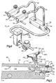
- Fig. 1 shows a schematic representation of a vacuum device 10, which is integrated in a machine 12, with which a collated collection of sheet-like printed products, such as. B. deposits, signatures, or the like is formed.
- the machine 12 has a plurality of containers that run along a conveyor are located.
- the sheet-like printed products are made from the containers Pickup points fed on the conveyor. 1 shows such a container 14, the further containers present along the conveyor line with the container 14 are identical.
- the conveyor has a variety of collation pockets 40 that move past the containers. The sheet-like printed products become those moving past the containers Bags 40 fed and thus the compilations collected therein educated.
- the container 14 has for receiving the arcuate printed products Support element 16, a removal window 18 and a movable signature support 19.
- the Removal window 18 is through the opposite ends of the Support element 16 and the movable support 18 limited. Because of the mobility of the movable support 18 to the support member 16 and away from it is the width of the Removal window variable.
- a plurality of signatures 20 are stacked on the support 16.
- the movable support 19 is at a certain distance arranged to support element 16 and in the direction indicated by arrow A. movable.
- the movable support 19 supports the outer end of the signature stack 20 in Container 14.
- the support 19 is shown schematically and can take various forms have, it could also be a rotating separating disc and is preferably on arranged at the same height with the support member 16 so that the signatures 20 in rest essentially horizontally.
- the support 19 can, however, relative to the lower edge of the Support element 16 may be arranged higher or lower, so that the Separation mechanism can be set so that it works optimally.
- a rotating drum 30 Under the removal window 18 of the container 14 is a rotating drum 30 arranged.
- the drum 30 is mounted so that it is clockwise about an axis 32 rotatable, as indicated by arrow B.
- the gripper fingers 34 and 36 are preferably located at a distance of 180 ° from each other and rotate with the drum 30.
- Die Gripper fingers 34 and 36 can also rotate independently of drum 30 and take a signature and release it.
- the variety of collation bags 40 is located under the rotating drum 30, they are preferably V-shaped Cross section and are part of the conveyor, not shown, which is relative to Container 14 and the other containers in the direction indicated by arrow C. emotional.
- the vacuum device is located next to the removal window 18 of the container 14 and the rotating drum 30 and includes a pair of suction heads 50 and 52 (see Fig. 2). It will be apparent to those skilled in the art that the vacuum device 10 only can comprise a suction head or more than two suction heads.
- the suction heads 50 and 52 are fixed to a rod 54 and rotate with it.
- the suction heads 50, 52 are also connected to a mechanism 56 which the suction heads 50, 52 for Signature stack 20 rotates towards and away from it, as by the respective arrows D and E indicated.
- the vacuum device 10 further includes one Pressure distributor 60 with an internal chamber 62, an electronically controlled one Air pressure valve 70 and a pressure regulator 80.
- Flexible air inlet lines 90, 92 connect the respective suction heads 50, 52 to the pressure distributor 60
- Air supply line 94 connects the pressure distributor 60 to the electronically controlled one Valve 70.
- Another air supply line 96 connects the valve 70 with the Pressure regulator 80.
- a main feed line 98 connects the pressure regulator 80 to a compressed air source, not shown, of approximately 80 psi (pounds per square inch).
- the electronically controlled valve 70 is a 0 - 24 volt DC device that passes through a wiring 100 is electrically connected to a system controller, not shown is. By actuating the system control, the electronically controlled valve 70 is opened and turned too, whereby the valve opens and closes.
- the suction head 50 includes an im present example essentially rectangular shaft 110, a suction cup 150 and a venturi suction tube 160.
- the shaft 110 includes an upper one facing the container 14 Surface 112, a first end 114 and a second end 116.
- a cylindrical Leg 120 extends from upper surface 112 of shaft 110 at an angle Winkel with respect to the first end 114 of the shaft.
- the angle ⁇ is preferably between 10 ° and 30 °.
- the shaft 110 shown in FIG. 3 is only one example Representation and could also be of a different shape and / or construction.
- the shaft 110 has an inner surface 130 in the form of a truncated cone that forms an axially oriented first passage 132.
- This first passage 132 extends from first end 114 to the second end 116 of the shaft 110 and points at the first end 114 a threaded part 134.
- a second passage 140 in shaft 110 extends from an area of the first passage 132 next to the threaded part 134 to the outside of the Shaft 110 and through the cylindrical leg 120.
- the second passage 140 is shown with a diameter smaller than the diameter of the first Passage 132, although it will be apparent to those skilled in the art that the first and the second passages 132 and 140 each have a substantially equal diameter can.
- the suction cup 150 is arranged on the cylindrical leg 120 of the shaft 110.
- the Suction cup 150 is made of a resilient material, such as. B. rubber, and has an upper section 152 and a lower section 154.
- the dimensions of the lower section 154 of the suction cup 150 are selected so that it closes well fits around the circumference of the cylindrical leg 120.
- the outside diameter of the upper section 152 of the suction cup 150 is larger than the outer diameter of the lower section 154.
- Upper section 152 has a peripheral lip 156, which determines a suction cavity 158 in the suction cup 150.
- the suction cavity 158 is generally after above towards the signature stack 20 located in the container 14.
- the ones in Shaft 110 located second passage 140, which extends through the cylindrical leg 120 extends therethrough is in fluid flow with the suction cavity 158 in the suction cup 110 connected.
- the venturi suction pipe 160 is located in part in the first passage 132 of the Shaft 110.
- Venturi suction tube 160 has an inner surface 162, one Outer surface 164, an inlet 166 and an outlet 168.
- the outer surface 164 of the Venturi suction pipe 160 consists of a first part 170, a second part 172 and a third part 174.
- the first part 170 is located next to the inlet 166 of the Venturi suction pipe 160 and has a thread which engages in a nut 176 which on the flexible air inlet line 90 is provided.
- the second part 172 of the outer surface 164 of the Venturi suction pipe 160 also has a thread.
- the thread on the second Part 172 of the suction pipe 160 fits into the threaded part 134 of the first passage 132 in Shaft 110.
- the third portion 174 of the outer surface 164 of the venturi suction tube 160 tapers from the second part 172 to the outlet 168, as can be seen in FIG. 3. If that Venturi suction pipe 160 is installed in the shaft 110, the outlet 168 of the Venturi suction tube 160 substantially radially within the second passage 140 of the Shaft 110.
- the inner surface 162 of the venturi suction tube 160 forms the flow path 180 from Inlet 166 of Venturi suction pipe 160 to its outlet 168.
- Flow path 180 includes a tapered or convergent section 182 that leads to a Neck portion 184 leads at outlet 168.
- a vacuum in the Suction heads 50 and 52 produce as follows: It is compressed air from the compressed air source the pressure regulator 80 which regulates the air pressure to a specific pressure level limited. The compressed air is then electronically via the air supply line 96 controlled valve 70 supplied. If the valve 70 from the control panel receives electrical signal, which says that in the suction heads 50 and 52, a vacuum is required, then the valve 70 opens so that the compressed air through the Feed line 94 flows to manifold 60, which then compresses the compressed air into the flexible one Distributes air lines 90 and 92, which the manifold 60 with the Venturi suction pipe 160 connect in the respective suction heads 50 and 52.
- the compressed air enters and becomes in the inlet 166 of each venturi 160 passed along the flow path 180.
- the air is accelerated through the tapered section 182 and thus reaches the neck portion 184 of the venturi suction tube 160.
- the accelerated Air flows through the neck portion 184, so the air has a relatively high total (or dynamic) and a relatively low static pressure, with outlet 168 of the venturi suction pipe 160, a vacuum is generated which extends to an outlet 168 surrounding area 190 extends in the shaft 110.
- the vacuum in the outlet 168 the area 190 surrounding the venturi suction pipe 160 is passed to the second passage 140, that extends outwards from this environment.
- the Signature 20a are moved relative to the signature stack 20.
- the movable support 19 is moved to the right as shown in Fig. 1 so that the signature 20a by the Removal window 18 can be moved.
- the mechanism 56 rotates the suction heads 50 and 52 clockwise in the direction indicated by arrow D to one Position, which is indicated in Fig. 1 by a dashed line. In this position the signature 20a is gripped by the gripper finger 34.
- the valve 70 is then closed so that the air supply to the venturi suction pipe 160 is cut off and consequently the vacuum is lost.
- the drum 30 and the gripper finger 34 with the gripped Signature 20a are rotated by about 180 °, then the gripper finger 34 gives the Signature 20a in one of the pockets 40 free.
- the mechanism has 56 the suction heads 50 and 52 in the direction of arrow E in their original position rotated under the removal window 18 of the container 14 and the retractable support 19th was moved to the left, as shown in FIG. 1, around the signature stack 20 in container 14 to support again.
- the valve 70 was also opened again, so that again Vacuum in the suction heads 50 and 52 can be generated to the next signature in the To take signature stack 20.
- the vacuum is therefore directly at the point of use, instead of at a remote location.
- This has the advantage that in the period between the opening of the electronically controlled valve and the creation of the vacuum in the Suction heads 50 and 52 achieved a quick effectiveness. It is also great Advantage that the vacuum in each of the suction heads 50 and 52 individually and independently can be generated. This ensures that when a suction head releases the vacuum loses and one signature cannot grip properly, the other suction head is still under full vacuum and grabs the signature, so that a much higher Reliability and feeding efficiency of the machine 12 is achieved.
- the operating efficiency of the Machine 12 generally improved because a vacuum is only created when needed.
- a vacuum in the Suction heads 50 and 52 generated.
- the timing of creating a vacuum in the suction heads 50 and 52 controlled dynamically by the system control.
- the latter method makes it possible according to the requirements for a given product or based on System parameters such as the speed of the machine 12, the timing of the vacuum to increase or delay. Such an adjustment of the timing can be either can be achieved manually or automatically.
- the present invention offers the further advantage that it is no longer it is necessary to blow out the air ducts to remove paper dust.
- anyone in the suction heads 50 and 52 sucked paper dust is removed from that by the first Passage 132 air flow flowing in each suction head back out of the suction heads away.
Applications Claiming Priority (2)
| Application Number | Priority Date | Filing Date | Title |
|---|---|---|---|
| US842530 | 1997-04-15 | ||
| US08/842,530 US5979889A (en) | 1997-04-15 | 1997-04-15 | Apparatus for generating a vacuum |
Publications (2)
| Publication Number | Publication Date |
|---|---|
| EP0872437A2 true EP0872437A2 (fr) | 1998-10-21 |
| EP0872437A3 EP0872437A3 (fr) | 1999-04-14 |
Family
ID=25287557
Family Applications (1)
| Application Number | Title | Priority Date | Filing Date |
|---|---|---|---|
| EP98105196A Ceased EP0872437A3 (fr) | 1997-04-15 | 1998-03-23 | Dispositif pour créer le vide |
Country Status (6)
| Country | Link |
|---|---|
| US (1) | US5979889A (fr) |
| EP (1) | EP0872437A3 (fr) |
| JP (1) | JPH10291664A (fr) |
| CN (1) | CN1093492C (fr) |
| CZ (1) | CZ99598A3 (fr) |
| DE (1) | DE19812596A1 (fr) |
Cited By (2)
| Publication number | Priority date | Publication date | Assignee | Title |
|---|---|---|---|---|
| EP1020388A2 (fr) * | 1999-01-15 | 2000-07-19 | MAN Roland Druckmaschinen AG | Dispositif de distribution et/ou de régulation d'air |
| EP1806306A1 (fr) * | 2006-01-10 | 2007-07-11 | Wohlenberg Buchbindesysteme GmbH | Procédé et dispositif destiné à basculer une partie d'une feuille pour séparer la feuille d'une pile |
Families Citing this family (24)
| Publication number | Priority date | Publication date | Assignee | Title |
|---|---|---|---|---|
| DE29822224U1 (de) * | 1998-12-14 | 1999-02-04 | Pfankuch Maschinen Gmbh | Vorrichtung zum Sammeln und Übergeben von Papierzuschnitten o.dgl. |
| NL1015254C2 (nl) * | 2000-05-18 | 2001-11-20 | Buhrs Zaandam Bv | Documentfeeder. |
| EP1186558A1 (fr) * | 2000-09-11 | 2002-03-13 | Grapha-Holding AG | Dispositif pour alimenter une ligne de transformation avec des produits imprimés |
| US6769678B2 (en) * | 2001-11-28 | 2004-08-03 | Heidelberger Druckmaschinen Ag | Sheet separating device |
| US7404536B2 (en) * | 2002-06-18 | 2008-07-29 | Syron Engineering & Manufacturing, Llc | Suction cup assembly including a quick release venturi |
| US7306222B2 (en) * | 2003-05-14 | 2007-12-11 | Goss International Americas, Inc. | Sheet material feeder |
| US20050200069A1 (en) * | 2004-03-12 | 2005-09-15 | G 01.Com Srl | Apparatus including a sucker with autoselection function for handling material |
| JP2008504186A (ja) * | 2004-06-24 | 2008-02-14 | ゴス インターナショナル アメリカス インコーポレイテッド | 被印刷製品を供給するための方法及び装置 |
| US8251688B2 (en) * | 2006-05-12 | 2012-08-28 | PH Realty, Inc. | Apparatus for a mold vacuum system and method of forming a sheet utilizing the system |
| JP2009299609A (ja) * | 2008-06-16 | 2009-12-24 | Denso Corp | エジェクタ |
| US8702089B2 (en) | 2011-07-22 | 2014-04-22 | Bell and Howell, LLC. | Method and system to feed inserts with a rotary and gripper system |
| GB2509183A (en) | 2012-12-21 | 2014-06-25 | Xerex Ab | Vacuum ejector with tripped diverging exit flow nozzle |
| WO2014094890A1 (fr) | 2012-12-21 | 2014-06-26 | Xerex Ab | Éjecteur à succion avec section elliptique divergente |
| GB2509184A (en) | 2012-12-21 | 2014-06-25 | Xerex Ab | Multi-stage vacuum ejector with moulded nozzle having integral valve elements |
| US9845636B2 (en) | 2013-01-07 | 2017-12-19 | WexEnergy LLC | Frameless supplemental window for fenestration |
| US9234381B2 (en) | 2013-01-07 | 2016-01-12 | WexEnergy LLC | Supplemental window for fenestration |
| US10196850B2 (en) | 2013-01-07 | 2019-02-05 | WexEnergy LLC | Frameless supplemental window for fenestration |
| US9691163B2 (en) | 2013-01-07 | 2017-06-27 | Wexenergy Innovations Llc | System and method of measuring distances related to an object utilizing ancillary objects |
| US9663983B2 (en) | 2013-01-07 | 2017-05-30 | WexEnergy LLC | Frameless supplemental window for fenestration incorporating infiltration blockers |
| US10883303B2 (en) | 2013-01-07 | 2021-01-05 | WexEnergy LLC | Frameless supplemental window for fenestration |
| GB201418117D0 (en) | 2014-10-13 | 2014-11-26 | Xerex Ab | Handling device for foodstuff |
| JP6332808B2 (ja) * | 2014-12-08 | 2018-05-30 | 株式会社エイチアンドエフ | ワーク搬送装置及びそれを用いたワーク搬送方法 |
| CN104773596A (zh) * | 2015-02-12 | 2015-07-15 | 苏州工业园区美柯乐制版印务有限责任公司 | 配页机书帖吸入装置 |
| AU2018278119B2 (en) | 2017-05-30 | 2023-04-27 | WexEnergy LLC | Frameless supplemental window for fenestration |
Citations (11)
| Publication number | Priority date | Publication date | Assignee | Title |
|---|---|---|---|---|
| GB1109717A (en) * | 1966-02-21 | 1968-04-10 | Blatt Leland F | Material handling device using suction cups |
| DE1912395A1 (de) * | 1969-03-12 | 1970-10-01 | Trepel Kg Maschinenfabrik | Mitnehmer fuer Vorrichtungen zum Abschieben plattenfoermiger Werkstuecke von Stapeln u.dgl. auf Transportbaender in Bearbeitungsmaschinen u.dgl. |
| US3884368A (en) * | 1973-04-23 | 1975-05-20 | Robert L Ballard | Panel destacker |
| US3998448A (en) * | 1974-10-31 | 1976-12-21 | C. I. Industries, Inc. | Continuous stack advancer for blank destacking |
| DE2852681A1 (de) * | 1978-12-06 | 1980-06-12 | Festo Maschf Stoll G | Saugglockentraeger |
| DE3526520C1 (de) * | 1985-07-19 | 1986-11-06 | Elpatronic Ag, Zug | Vorrichtung zum Aussondern nicht verwendbarer plattenförmiger Teile |
| US4986524A (en) * | 1989-01-04 | 1991-01-22 | Dundee Mills, Inc. | Label injector for hemming machines |
| GB2247450A (en) * | 1990-07-27 | 1992-03-04 | Felix International Limited | Apparatus for separating signatures from a stack |
| US5603599A (en) * | 1994-09-28 | 1997-02-18 | Tetra Laval Holdings & Finance S.A. | Vacuum system |
| EP0765736A1 (fr) * | 1995-09-28 | 1997-04-02 | H.J. Langen & Sons Inc. | Applicateur rotatif des objets |
| EP0775655A1 (fr) * | 1995-11-22 | 1997-05-28 | MAN Roland Druckmaschinen AG | Dispositif de commande pour air sous vide et/ou sous pression |
Family Cites Families (5)
| Publication number | Priority date | Publication date | Assignee | Title |
|---|---|---|---|---|
| US3591167A (en) * | 1969-02-27 | 1971-07-06 | Signode Corp | Sheet feeding apparatus |
| US4157692A (en) * | 1977-02-23 | 1979-06-12 | Opelika Manufacturing Corp. | Label dispensing system for use with sewing apparatus |
| US4531723A (en) * | 1982-04-02 | 1985-07-30 | Metromail Corporation | Paper sheet separator |
| EP0207778A3 (fr) * | 1985-07-03 | 1988-06-15 | Portals Engineering Limited | Machine de rassemblement |
| US4958824A (en) * | 1988-11-09 | 1990-09-25 | Spartanics, Ltd. | Automatic strip and sheet loader system |
-
1997
- 1997-04-15 US US08/842,530 patent/US5979889A/en not_active Expired - Fee Related
-
1998
- 1998-03-13 CN CN98101105A patent/CN1093492C/zh not_active Expired - Fee Related
- 1998-03-23 DE DE19812596A patent/DE19812596A1/de not_active Withdrawn
- 1998-03-23 EP EP98105196A patent/EP0872437A3/fr not_active Ceased
- 1998-04-01 CZ CZ98995A patent/CZ99598A3/cs unknown
- 1998-04-10 JP JP10098958A patent/JPH10291664A/ja active Pending
Patent Citations (11)
| Publication number | Priority date | Publication date | Assignee | Title |
|---|---|---|---|---|
| GB1109717A (en) * | 1966-02-21 | 1968-04-10 | Blatt Leland F | Material handling device using suction cups |
| DE1912395A1 (de) * | 1969-03-12 | 1970-10-01 | Trepel Kg Maschinenfabrik | Mitnehmer fuer Vorrichtungen zum Abschieben plattenfoermiger Werkstuecke von Stapeln u.dgl. auf Transportbaender in Bearbeitungsmaschinen u.dgl. |
| US3884368A (en) * | 1973-04-23 | 1975-05-20 | Robert L Ballard | Panel destacker |
| US3998448A (en) * | 1974-10-31 | 1976-12-21 | C. I. Industries, Inc. | Continuous stack advancer for blank destacking |
| DE2852681A1 (de) * | 1978-12-06 | 1980-06-12 | Festo Maschf Stoll G | Saugglockentraeger |
| DE3526520C1 (de) * | 1985-07-19 | 1986-11-06 | Elpatronic Ag, Zug | Vorrichtung zum Aussondern nicht verwendbarer plattenförmiger Teile |
| US4986524A (en) * | 1989-01-04 | 1991-01-22 | Dundee Mills, Inc. | Label injector for hemming machines |
| GB2247450A (en) * | 1990-07-27 | 1992-03-04 | Felix International Limited | Apparatus for separating signatures from a stack |
| US5603599A (en) * | 1994-09-28 | 1997-02-18 | Tetra Laval Holdings & Finance S.A. | Vacuum system |
| EP0765736A1 (fr) * | 1995-09-28 | 1997-04-02 | H.J. Langen & Sons Inc. | Applicateur rotatif des objets |
| EP0775655A1 (fr) * | 1995-11-22 | 1997-05-28 | MAN Roland Druckmaschinen AG | Dispositif de commande pour air sous vide et/ou sous pression |
Cited By (4)
| Publication number | Priority date | Publication date | Assignee | Title |
|---|---|---|---|---|
| EP1020388A2 (fr) * | 1999-01-15 | 2000-07-19 | MAN Roland Druckmaschinen AG | Dispositif de distribution et/ou de régulation d'air |
| EP1020388A3 (fr) * | 1999-01-15 | 2001-05-23 | MAN Roland Druckmaschinen AG | Dispositif de distribution et/ou de régulation d'air |
| EP1398285A1 (fr) * | 1999-01-15 | 2004-03-17 | MAN Roland Druckmaschinen AG | Dispositif de distribution et/ou de régulation d'air |
| EP1806306A1 (fr) * | 2006-01-10 | 2007-07-11 | Wohlenberg Buchbindesysteme GmbH | Procédé et dispositif destiné à basculer une partie d'une feuille pour séparer la feuille d'une pile |
Also Published As
| Publication number | Publication date |
|---|---|
| CN1196326A (zh) | 1998-10-21 |
| DE19812596A1 (de) | 1998-11-05 |
| JPH10291664A (ja) | 1998-11-04 |
| CZ99598A3 (cs) | 1998-11-11 |
| EP0872437A3 (fr) | 1999-04-14 |
| CN1093492C (zh) | 2002-10-30 |
| US5979889A (en) | 1999-11-09 |
Similar Documents
| Publication | Publication Date | Title |
|---|---|---|
| EP0872437A2 (fr) | Dispositif pour créer le vide | |
| EP0660777B1 (fr) | Dispositif destine a amener et a evacuer des plaques d'impression | |
| EP0660778B1 (fr) | Procede et dispositif visant a evacuer des plaques d'impression | |
| DE10001580B4 (de) | Greifervorrichtung | |
| DE2043738C3 (de) | Zufuhrvorrichtung für einzelne Papierbogen | |
| DE102008051919A1 (de) | Vorrichtung und Verfahren zum Sortieren von Gegenständen insbesondere von Flaschen | |
| DE102019106766A1 (de) | Etikettenspender mit etikettenablösefunktion, roboter undetikettenablöseverfahren | |
| EP0897890B1 (fr) | Procédé et dispositif pour produire un courant de produits tournés avec une pince de préhension de coin | |
| EP2690040A2 (fr) | Dispositif de séparation d'objets plats pliables individuels de la face inférieure d'une pile de tels objets | |
| EP1839897B1 (fr) | Assembleuse et brocheuse combinées avec un dispositif d'alimentation de feuilles pliées | |
| DE2737558C2 (de) | Blattvereinzelungsgerät | |
| CH652344A5 (de) | Vorgreifer einer bogenanlegevorrichtung. | |
| DE3545271A1 (de) | Verfahren und vorrichtung zum abbremsen und auslegen von in einer druckmaschine bedruckten bogen oder bogenpaketen | |
| DE10254332A1 (de) | Falzzylinder | |
| CH672775A5 (fr) | ||
| EP1038671B1 (fr) | Dispositif de séparation des feuilles | |
| EP1443006B1 (fr) | Procédé pour rompre et ventiler une pile des feuilles, en particulier une pile des feuilles de papier | |
| CH693336A5 (de) | Vorrichtung zum Transportierenflächiger Gegenstände. | |
| EP0661213A1 (fr) | Dispositif d'introduction d'étiquettes et procédé de fonctionnement | |
| DE2117311B2 (de) | Vorrichtung zum Abziehen von Papierblättern von einem Stapel | |
| DE10245698B4 (de) | Bogenvereinzelungsvorrichtung | |
| CH690576A5 (de) | Vorrichtung zum Verarbeiten von Druckereiprodukten. | |
| EP1228991B1 (fr) | Aiguilles ajustables pour un dispositif de séparation de feuilles | |
| EP1149791A2 (fr) | Dispositif pour prélever une feuille d'essai dans un appareil de sortie d'une machine à imprimer des feuilles | |
| EP3197801B1 (fr) | Dispositif et procédé de séparation de parties d'un produit à plusieurs parties |
Legal Events
| Date | Code | Title | Description |
|---|---|---|---|
| PUAI | Public reference made under article 153(3) epc to a published international application that has entered the european phase |
Free format text: ORIGINAL CODE: 0009012 |
|
| 17P | Request for examination filed |
Effective date: 19980323 |
|
| AK | Designated contracting states |
Kind code of ref document: A2 Designated state(s): BE CH DE FR GB IT LI NL |
|
| AX | Request for extension of the european patent |
Free format text: AL;LT;LV;MK;RO;SI |
|
| PUAL | Search report despatched |
Free format text: ORIGINAL CODE: 0009013 |
|
| AK | Designated contracting states |
Kind code of ref document: A3 Designated state(s): AT BE CH DE DK ES FI FR GB GR IE IT LI LU MC NL PT SE |
|
| AX | Request for extension of the european patent |
Free format text: AL;LT;LV;MK;RO;SI |
|
| AKX | Designation fees paid |
Free format text: BE CH DE FR GB IT LI NL |
|
| 17Q | First examination report despatched |
Effective date: 20020318 |
|
| STAA | Information on the status of an ep patent application or granted ep patent |
Free format text: STATUS: THE APPLICATION HAS BEEN REFUSED |
|
| 18R | Application refused |
Effective date: 20040402 |