EP0765736A1 - Applicateur rotatif des objets - Google Patents
Applicateur rotatif des objets Download PDFInfo
- Publication number
- EP0765736A1 EP0765736A1 EP96306957A EP96306957A EP0765736A1 EP 0765736 A1 EP0765736 A1 EP 0765736A1 EP 96306957 A EP96306957 A EP 96306957A EP 96306957 A EP96306957 A EP 96306957A EP 0765736 A1 EP0765736 A1 EP 0765736A1
- Authority
- EP
- European Patent Office
- Prior art keywords
- planetary
- moon
- axis
- rotation
- pick
- Prior art date
- Legal status (The legal status is an assumption and is not a legal conclusion. Google has not performed a legal analysis and makes no representation as to the accuracy of the status listed.)
- Granted
Links
Images


Classifications
-
- B—PERFORMING OPERATIONS; TRANSPORTING
- B65—CONVEYING; PACKING; STORING; HANDLING THIN OR FILAMENTARY MATERIAL
- B65H—HANDLING THIN OR FILAMENTARY MATERIAL, e.g. SHEETS, WEBS, CABLES
- B65H3/00—Separating articles from piles
- B65H3/42—Separating articles from piles by two or more separators mounted for movement with, or relative to, rotary or oscillating bodies
-
- B—PERFORMING OPERATIONS; TRANSPORTING
- B65—CONVEYING; PACKING; STORING; HANDLING THIN OR FILAMENTARY MATERIAL
- B65H—HANDLING THIN OR FILAMENTARY MATERIAL, e.g. SHEETS, WEBS, CABLES
- B65H3/00—Separating articles from piles
- B65H3/08—Separating articles from piles using pneumatic force
- B65H3/0808—Suction grippers
- B65H3/0891—Generating or controlling the depression
-
- B—PERFORMING OPERATIONS; TRANSPORTING
- B65—CONVEYING; PACKING; STORING; HANDLING THIN OR FILAMENTARY MATERIAL
- B65H—HANDLING THIN OR FILAMENTARY MATERIAL, e.g. SHEETS, WEBS, CABLES
- B65H5/00—Feeding articles separated from piles; Feeding articles to machines
- B65H5/08—Feeding articles separated from piles; Feeding articles to machines by grippers, e.g. suction grippers
- B65H5/12—Revolving grippers, e.g. mounted on arms, frames or cylinders
-
- B—PERFORMING OPERATIONS; TRANSPORTING
- B31—MAKING ARTICLES OF PAPER, CARDBOARD OR MATERIAL WORKED IN A MANNER ANALOGOUS TO PAPER; WORKING PAPER, CARDBOARD OR MATERIAL WORKED IN A MANNER ANALOGOUS TO PAPER
- B31B—MAKING CONTAINERS OF PAPER, CARDBOARD OR MATERIAL WORKED IN A MANNER ANALOGOUS TO PAPER
- B31B2100/00—Rigid or semi-rigid containers made by folding single-piece sheets, blanks or webs
-
- B—PERFORMING OPERATIONS; TRANSPORTING
- B31—MAKING ARTICLES OF PAPER, CARDBOARD OR MATERIAL WORKED IN A MANNER ANALOGOUS TO PAPER; WORKING PAPER, CARDBOARD OR MATERIAL WORKED IN A MANNER ANALOGOUS TO PAPER
- B31B—MAKING CONTAINERS OF PAPER, CARDBOARD OR MATERIAL WORKED IN A MANNER ANALOGOUS TO PAPER
- B31B2120/00—Construction of rigid or semi-rigid containers
- B31B2120/30—Construction of rigid or semi-rigid containers collapsible; temporarily collapsed during manufacturing
-
- B—PERFORMING OPERATIONS; TRANSPORTING
- B31—MAKING ARTICLES OF PAPER, CARDBOARD OR MATERIAL WORKED IN A MANNER ANALOGOUS TO PAPER; WORKING PAPER, CARDBOARD OR MATERIAL WORKED IN A MANNER ANALOGOUS TO PAPER
- B31B—MAKING CONTAINERS OF PAPER, CARDBOARD OR MATERIAL WORKED IN A MANNER ANALOGOUS TO PAPER
- B31B50/00—Making rigid or semi-rigid containers, e.g. boxes or cartons
- B31B50/006—Controlling; Regulating; Measuring; Improving safety
-
- B—PERFORMING OPERATIONS; TRANSPORTING
- B31—MAKING ARTICLES OF PAPER, CARDBOARD OR MATERIAL WORKED IN A MANNER ANALOGOUS TO PAPER; WORKING PAPER, CARDBOARD OR MATERIAL WORKED IN A MANNER ANALOGOUS TO PAPER
- B31B—MAKING CONTAINERS OF PAPER, CARDBOARD OR MATERIAL WORKED IN A MANNER ANALOGOUS TO PAPER
- B31B50/00—Making rigid or semi-rigid containers, e.g. boxes or cartons
- B31B50/02—Feeding or positioning sheets, blanks or webs
- B31B50/04—Feeding sheets or blanks
- B31B50/06—Feeding sheets or blanks from stacks
- B31B50/062—Feeding sheets or blanks from stacks from the underside of a magazine
-
- B—PERFORMING OPERATIONS; TRANSPORTING
- B31—MAKING ARTICLES OF PAPER, CARDBOARD OR MATERIAL WORKED IN A MANNER ANALOGOUS TO PAPER; WORKING PAPER, CARDBOARD OR MATERIAL WORKED IN A MANNER ANALOGOUS TO PAPER
- B31B—MAKING CONTAINERS OF PAPER, CARDBOARD OR MATERIAL WORKED IN A MANNER ANALOGOUS TO PAPER
- B31B50/00—Making rigid or semi-rigid containers, e.g. boxes or cartons
- B31B50/74—Auxiliary operations
- B31B50/76—Opening and distending flattened articles
- B31B50/80—Pneumatically
- B31B50/804—Pneumatically using two or more suction devices on a rotating element
-
- B—PERFORMING OPERATIONS; TRANSPORTING
- B65—CONVEYING; PACKING; STORING; HANDLING THIN OR FILAMENTARY MATERIAL
- B65H—HANDLING THIN OR FILAMENTARY MATERIAL, e.g. SHEETS, WEBS, CABLES
- B65H2403/00—Power transmission; Driving means
- B65H2403/40—Toothed gearings
- B65H2403/48—Other
- B65H2403/481—Planetary
-
- B—PERFORMING OPERATIONS; TRANSPORTING
- B65—CONVEYING; PACKING; STORING; HANDLING THIN OR FILAMENTARY MATERIAL
- B65H—HANDLING THIN OR FILAMENTARY MATERIAL, e.g. SHEETS, WEBS, CABLES
- B65H2403/00—Power transmission; Driving means
- B65H2403/50—Driving mechanisms
- B65H2403/54—Driving mechanisms other
- B65H2403/543—Driving mechanisms other producing cycloids
-
- B—PERFORMING OPERATIONS; TRANSPORTING
- B65—CONVEYING; PACKING; STORING; HANDLING THIN OR FILAMENTARY MATERIAL
- B65H—HANDLING THIN OR FILAMENTARY MATERIAL, e.g. SHEETS, WEBS, CABLES
- B65H2406/00—Means using fluid
- B65H2406/40—Fluid power drive; Fluid supply elements
- B65H2406/41—Valves
Definitions
- This invention is directed to an object feeder, more particularly to a rotary object feeder that feeds an object by rotating the object about three parallel, axes of rotation.
- the suction cups move along a hypocycloidal path, and will pick-up objects at points along their path where the suction-cups are travelling in a direction which is perpendicular to the objects.
- the perpendicular movement may be somewhat abrupt.
- the object to be picked up is rotated about an additional axis, which may significantly increase the net velocity of the object at certain points along its path. Accordingly, object feeders using this solution do not lend themselves to operation at high speeds.
- the object is rotated inwardly toward a central axis. This restricts the size and number of objects that can be handled simultaneously by the object feeder.
- the present invention is directed to a rotary object feeder, which feeds objects from a first location to a second location by rotating the object about three axes.
- the object feeder feeds the object from a pick-up location to an off-loading location, by moving an object pick-up member along a trajectory formed by rotating the object pick-up member about a first axis of rotation; rotating this first axis of rotation about a second axis of rotation substantially parallel to the first axis of rotation and spaced therefrom; rotating the second axis of rotation about a third axis of rotation substantially parallel to the second axis of rotation and spaced therefrom.
- the first, second and third axes of rotation may be analogized to moon, planet and sun axes in a solar system.
- the resulting trajectory of the object about a third axis is hypocycloidal.
- the object passes at least one point at which the object is at a farthest distance from this third axis. This farthest location is reached when the object, the first axis, the second axis and the third axis of rotation are collinear. This location can be considered a vertex of the object's trajectory.
- the object will change its radial direction away from the first axis toward the second axis.
- the number of vertices along the object's trajectory as the object rotates about the third axis will vary depending on the relative rates of rotation of the first axis about the second axis and the second axis about the third axis.
- the object's trajectory will have at least one vertex for each rotation of the object about the third axis.
- the object will only reach a vertex of its trajectory after the second axis has rotated about the third axis at least once.
- the choice of distances from the third axis to the second axis; from the second axis to the third axis; and from the third axis to the object combined with the relative rates of rotation of the object about its three axes may be chosen to minimize the tangential velocity of the object in its orbit about the third axis at these vertices.
- the rate of rotation of the second axis about the third axis (angular velocity ⁇ 1 ), and the rate of rotation of the first axis about the second axis (angular velocity ⁇ 2 ) will be chosen as integer multiples of each other, with ⁇ 2 > ⁇ 1 .
- the trajectory of the object will have ⁇ 2 / ⁇ 1 vertices for each rotation of the second axis about the third axis.
- the location of these vertices relative to some fixed point, (for example, the location of the third axis) may be arbitrarily selected and will remain the same for each rotation of the second axis about the third axis.
- a rotary object feeder in accordance with this invention need not be limited to a single pick-up member mounted rotatable about three axis.
- An object feeder in accordance with this invention may have any number of pick-up members, each having arbitrary rates of rotation about a first, second and third axis. In this way, the invention may extend to a rotary carton feeder, in which the pick-up members may be analogized to moons in a solar system having numerous planets.
- this invention is particularly well suited for use with a rotary carton feeder which will have enhanced advantages when numerous planetary members are mounted about a third axis such that the pick-up members reach vertices along their trajectories at equidistant points from the third axis. Moreover, if numerous pick-up members rotate about a third axis, it will be advantageous if a number of these pick-up members travel along identical trajectories so that they reach the vertices of their paths at the same locations. The vertices may then be used as pick-up, operating and drop-off stations for an object.
- a rotary object feeder comprising: a support; a carrier member rotatably mounted to said support at a sun axis of rotation; a planetary member rotatably mounted to said carrier member at a planetary axis of rotation spaced from said sun axis of rotation; a moon member rotatably mounted to said planetary member at a moon axis of rotation spaced from said planetary axis of rotation; an object pick-up member mounted to said moon member; said sun axis of rotation, said planetary axis of rotation and said moon axis of rotation being substantially parallel; means for continuously rotating said carrier member, said planetary member, and said moon member at fixed relative angular velocities, with at least one of said planetary member and said moon member rotating in a direction opposite to that of said carrier member, such that said pick-up member moves through a pick-up location at a reduced velocity relative to said support.
- a rotary object feeder comprises:
- a method for feeding an object from a pick-up location to an off-loading location comprising the steps of: moving an object pick-up member along a trajectory by (a) rotating said object pick-up member about a first axis of rotation; (b) rotating said first axis of rotation about a second axis of rotation substantially parallel to said first axis of rotation and spaced therefrom; (c) rotating said second axis of rotation about a third axis of rotation substantially parallel to said second axis of rotation and spaced therefrom; the rotation of at least one of steps (b) and (c) being in a direction opposite to the direction of rotation of step (a); picking up an object with said pick-up member at a pick-up location along said trajectory; and releasing said object at an off-loading location along said trajectory.
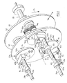
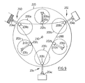
- a rotary object feeder generally designated 18 having three identical planetary members 22a, 22b and 22c.
- a rotary object feeder 18 having a carrier member 20.
- Carrier member 20 is comprised of two circular disks 50 and 52.
- Disks 50 and 52 are made of a durable, rigid material such as steel or aluminum.
- a main shaft 36 is fixedly mounted to disk 52.
- Main shaft 36 is coaxial with a sun axis 30.
- a sun gear 38 is fixedly mounted on a support frame 16, adjacent to the rear side of disk 52 farthest from disk 50.
- Sun gear 38 is mounted on main shaft 36 and has a centre axis coincident with sun axis 30.
- Shaft 36 is rotatable relative to fixed sun gear 38.
- Three identical planetary members 22a, 22b and 22c are mounted on carrier member 20.
- the three planetary members are mounted about planetary axes 32a, 32b and 32c at equal distances from sun axis 30, and at equal distances from each other. Only one planetary member 22a will be described herein in detail but it will be understood that planetary members 22b and 22c are identical in structure.
- Planetary member 22a is rotatably mounted on carrier member 20 about a planetary axis 32a.
- Planetary axis 32a is oriented parallel to sun axis 30.
- Planetary member 22a is comprised of circular disk 54a and a lever 56a.
- Circular disk 54a and lever 56a are made of a material similar to that of circular disks 50 and 52.
- Circular disk 50 has a circular cut-out for seating planetary member 22a and particularly disk 54a and accordingly may, if desired be mounted with its outer surface flush with the outer surface of disk 50.
- Bearings 80a are interposed between disk 50 and disk 54a.
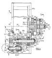
- An idler gear 44a is rotatably mounted on disk 52 about shaft 33a so that it is freely rotatable about shaft 33a relative to disk 52 on the side of disk 52 farthest from disk 50.
- Idler gear 44a engages sun gear 38.
- Idler gear 44a also engages a planetary gear 46a.
- Planetary gear 46a is fixedly mounted on planetary shaft 48a, near an end of a planetary shaft 48a.
- Planetary shaft 48a extends through a cut away in circular disk 52, and through a cut away in circular disk 56a.
- a fixing shaft 58a is attached at one end to disk 54a and at another to lever 56a.
- Fixing shaft 58a acts as a counterweight mounted between dish 54a and lever 56a, diametrically opposite moon shaft 60a and is adapted in combination with the shaping of lever 56a to balance the weight of planetary system 22a about planetary shaft 48a, thereby providing a smooth balanced rotation about axis 32a.
- a second end of planetary shaft 48a is fixedly attached to disk 54a at the centre of disk 54a.
- a housing 62a is fixedly mounted to the inner side of circular disk 52 and surrounds planetary shaft 48a.
- Ball bearings 84a are mounted in housing 62a and are interposed between planetary shaft 48a relative to housing 62a, thus permitting rotation of shaft 48a without housing 62a.
- An idler gear 72a is rotatably mounted on an inner side of lever 56a closest to circular disk 54a on shaft 53a, and engages planetary sun gear 70a.
- a moon gear 74a is fixedly mounted to moon shaft 60a. Moon gear 74a is also engaged by idler gear 72a.
- Moon member 24a is fixedly mounted on moon shaft 60a on planetary member 22a and is rotatable, about moon axis 34a with moon shaft 60a.
- Moon member 24a has an extension member 40a and a shaft 42a.
- Shaft 42a extends from extension member 40a in a direction parallel to moon axis 34a.
- Extension member 40a is mounted to moon shaft 60a near one of its ends.
- Extension member 40a is generally rectangular in shape, made of a rigid material, and mounted near one of its ends with its long axis perpendicular to moon axis 34a.
- Object pick-up member 26a is fixedly mounted on shaft 42a and has a pair of vacuum suction cups 28a.
- Vacuum generator 102a uses compressed air at one inlet and converts this compressed air into a stream of attracted air (ie. a vacuum).
- a vacuum generator suitable for use with this invention is produced by PiscoTM Pneumatic Equipment, sold under model No. H10-016C or H10-018C.
- Vacuum generator 102a is connected to one end of hose 110a. The other end of hose 110a is connected to nib 104a.
- Hose 110a thus provides a means of air communication between vacuum generator 102a and nib 104a.
- Nib 104a extends in a direction along axis 32a from moon shaft 60a which is hollow.
- the hollow interior of moon shaft 60a forms an air passage 114a from an end connector 106a to nib 104a.
- End connector 106a is mounted on swivel joint 122a which permits end connector 106a to rotate about axis 34a.
- End connector 106a is connected to an end of hose 112a.
- the other end of hose 112a is connected to nib 108a.
- Nib 108a extends in a direction perpendicular to axis 32a from planetary shaft 48a which is also hollow.
- Planetary shaft 48a defines air passage 116a which extends from connector 117a to nib 108a.
- Connector 117a is mounted on swivel joint 121a permitting connector 117a to rotate about axis 32a.
- Hose 118a extends from connector 117a to an electronic control valve (not shown).
- a hose (also not shown) extends from the electronic control valve to manifold 124.
- the hose is connected to a nib (not shown) on the manifold.
- Control valve 130b is connected by hose 131b to nib 120b and it controls the air flow to vacuum generator 102b.
- Nib 120b passes extends from manifold 124 and air passage 119b extending through hollow shaft 36.
- a suitable electronic control valve for use in this embodiment is sold by MACTM Valves as part No. 111B/113B-111CA.
- Control valve 130b is connected to control wires (not shown) which extend to slip ring 37, as described below.
- a computer control system provides control valve 130b with appropriate control signals to activate and de-activate the flow of compressed air to vacuum generator 102b.
- a connector 126 extending from an end of shaft 36 is connected to a source of air pressure (not shown).
- Extension member 40a and shaft 42a are designed so that suction cups 28a have their pick-up surface along moon axis 34a.
- a source of rotational power drives shaft 36 at an angular velocity of ⁇ 1 .
- a source of positive air pressure is fed to connector 126.
- Shaft 36 causes disk 52 and disk 50 along with planetary members 46a, 46b and 46c and their corresponding planetary axis, to rotate about the sun axis 30 at angular velocity ⁇ 1 and relative to sun gear 42. Consequently, idler gear 44a is driven about sun gear 38 and engages sun gear 38 to cause idler gear 44a to rotate about its shaft 33 in a direction the same as the direction of rotation of disk 52, as illustrated in Figure 5.
- Planetary spur gear 46a is engaged by idler gear 44a and is rotated about its planetary axis 32a in the opposite direction as idler gear 44a and disc 52 at an angular velocity ⁇ 2 .
- Planetary spur gear 46a fixedly attached to planetary shaft 48a, causes planetary shaft 48a to rotate with spur gear 46a.
- Planetary shaft 48a, attached to disk 54a causes disk 54a to rotate along with planetary shaft 48a at an angular velocity ⁇ 2 .
- lever 56a is attached to disk 54a by fixing shaft 58a
- lever 56a rotates with disk 54a about axis 32a.
- Planetary sun gear 70a is attached to housing 62 and is stationary with respect to disk 52.
- Idler gear 72a secured to lever 56a by shaft 53, is driven about and engages planetary sun gear 70a.
- Idler gear 72a thereby rotates about shaft 53a in the same direction of rotation as disk 56a.
- Moon spur gear 74a is engaged by idler gear 72a and moon spur gear 74a thereby rotates in the opposite direction as idler gear 72a and disc 54a, with an angular velocity ⁇ 3 equal in magnitude to ⁇ 2 .
- spur gear 74a is fixedly attached to moon shaft 60a, moon shaft 60a rotates with moon spur gear 74a.
- Moon member 24a rotates along with moon shaft 60a.
- pick-up member 24a rotates in a direction opposite the direction of rotation of planetary member 22a at the same angular velocity as planetary member 22a, pick-up member 24a and suction cups 28a will always remain generally outwardly facing.
- extension member 24a is mounted so that pick-up member 42a is always outwardly facing with respect to axis 30.
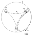
- pick-up member 24a traverses a generally triangular trajectory 88 as shown in Figure 2.
- the velocity of suction cups 28a in a direction tangent to the rotation of the carrier is zero.
- This zero tangential velocity results from the contribution of the rotation of pick-up member 24a about axes 34a, 32a and 30.
- Zero tangential velocity at the vertices is achieved through a balancing choice of the ratios of rotation of planetary member 22a to carrier member 20; the positioning of axes of rotation 34a, 32a and 30 and the choice of the length of extension member 40a, as will be described later in further detail.
- suction cups 28a pass through pick-up location 90.
- a carton magazine or feeder for holding folded cartons.
- Suction cups 28a make contact with a top-most folded carton at pick-up location 90 while travelling in a direction perpendicular to the planar surface of the folded cartons.
- an electric control valve (not shown) causes the inlet of vacuum generator 102a to be provided with pressurized air.
- control valve is provided with control signals by means of control wires (not shown). These control wires are fixed relative to disc 52 make further contact with control wires 39 through slip ring 37. Control wires 39 are stationery relative to support 16 on the opposite side of slip ring 37. Thus, the control wires are stationary relative to disc 50 and mount 16.
- a suitable slip ring for use with this invention is sold by LittonTM, as part No. AC4598.
- the pressurized air is fed to vacuum generator 102a via air passages or cavities 126, 116a, 114a and hoses 118a and 112a.
- Vacuum generator 102a converts this pressurized air into a constant source of suction. This suction is fed to suction cups 28a, thereby causing a carton to adhere to suction cups 28a at pick-up location 90. In some applications, it is possible for the vacuum generator to be eliminated and a vacuum applied through the entire air system.
- the electrical actuator retains pressurized air at vacuum generator 102a and thereby suction at suction cup 28 until suction cup 28a reaches off-loading location 94.
- Suction cup 28a transports a folded carton from pick-up location 90 along trajectory 88 to operating location 92. As the folded carton travels from pick-up location 90, suction cup 28 remains outwardly facing because of suction cup 28a's rotation in an opposite direction and at an angular velocity equal to that of planetary member 22a.
- hose 118a does not become twisted as manifold 124 rotates.
- Nib 104a need not rotate about axis 34a because there is no movement of shaft 42a relative to shaft 60a.
- an expansion unit (not shown).
- the folded carton has zero tangential velocity.
- the carton expander is located tangent to carrier 20 at operating location 92.
- the expander engages the folded carton and pulls the carton apart in a direction radial to carrier 20.
- Suction cup 28a further transports the unfolded carton along trajectory 88 to off-loading location 94.
- the electromechanical actuator releases the negative pressure at suction cups 28a. Accordingly, the unfolded carton, having zero tangential velocity at off-loading location 94 is released.
- a transport mechanism (not shown) on which the unfolded carton is released. The unfolded carton is then transported by the transport mechanism away from the carton feeder to a location (not shown) where the carton is further processed.
- Pick-up location 90, operating location 92 and off-loading location 94 are equally spaced from each other along the periphery of carrier 20. While pick-up member 24a follows trajectory 88, pick-up member 24c follows the same trajectory, but lags by 120° of rotation of carrier 20. Similarly, pick-up member 24c further lags 120° behind pick-up member 24b. Thus, when pick-up member 24a passes through pick-up location 90, pick-up member 24c passes through off-loading location 94, and pick-up member 24b passes through operating location 92. Vacuum generators 102b and 102c are actuated as pick-up members 24b and 24c pass through pick-up location 90.
- pick-up members 24b and 24c pass through off-loading location 94.
- pick-up members 24b and 24c pass through off-loading location 94.
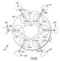
- a rotary object feeder generally designated 218 having two sets of three identical planetary members; a first set 200a, 200b, 200c; and a second set 202a, 202b, and 202c.
- the size of planetary members 200, 202 and the carrier member 220 are chosen, so that two sets of three planetary members may be mounted on a single carrier member.
- the six planetary members are arranged to function as two sets of three planetary members.
- the first set comprising planetary member 200a, 200b, and 200c having moon members 210a, 210b and 210c mounted thereon.
- Each moon member further comprises a pick-up member 206a, 206b and 206c.
- Each pick-up member 206a, 206b and 206c travels along hypocycloidal trajectory 288 generally in the triangular pattern illustrated.
- Each of the sets of moon members 204 and 210 rotate three times about a planetary axes for each rotation of carrier 220 about a sun axis, in an opposite direction as carrier 220.
- the pick-up members 204 travel along the trajectory 288 but lag pick-up members 206, by 60° of rotation of carrier member 220 about sun axis 230.
- the vertices of the trajectory 288 are located at positions, 290, 292 and 294. Each of the pick-up members 204 and 206 pass through each vertex once for every rotation of carrier 220. Located at these vertices are a folded carton feeder, an operating unit and a transport unit respectively, as with the embodiment 1 shown in Figures 1 - 6. As in Embodiment 1 of Figures 1-6, a vacuum generator on each of members 204, and 206 is actuated as each of the pick-up members passes through the pick-up location 290. Suction cups forming pick-up members 204 and 206 pick-up a folded carton at pick-up location 290, transport it to operating location 292 where the folded carton is expanded, transport it to a further off-loading location 294 where it is released.
- each suction cup will pass through pick-up 290, operating 292 and off-loading location 294 with zero tangential velocity.
- each set of three planetary members follow a different trajectory.
- one set of planetary members 200a, 200b, 200c follows a hypocycloidal trajectory generally marked as 250.
- a second set of planetary members 202a, 202b and 202c follows a hypocycloidal trajectory generally marked as 252.
- the vertices of each trajectory are at different locations relative to the frame support (not shown).
- a rotary feeder according to such an embodiment may be adapted for two pick-up locations 280, 290, two operating locations 282, 292 and two off-loading locations 284, 294.
- Each set of pick-up members 200 and 202 will pass along a generally hypocycloidal trajectory 250 or 252 having one of the pick-up locations 280 or 290; one of the operating locations 282 or 292 and one of the off-loading locations 284 or 294 at its vertices.
- the rotary feeder may be used to feed six folded cartons from two different pick-up locations to two different off-loading locations for each rotation of carrier member 220.
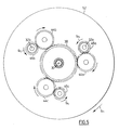
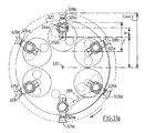
- each planetary member 322a - 322f is geared so that it rotates six times about planetary axes 332a - 332f for each rotation of carrier member 320 about sun axis 330.
- the trajectory 388 of each planetary member is accordingly pseudo-hexagonal with six vertices, as shown in Figures 11 and 11a.
- the carton feeder may be adapted to have two sets of pick-up, operating, and off-loading locations, or it may be adapted to have a single pick-up and off-loading position with four operating positions, depending on the requirements of the particular application.
- each object pick-up member will pick-up a folded carton from a magazine at a loading station 390.
- the folded carton is then rotated about the path shown in Figures 11 and lla to a carton erection station 392.
- a conventional carton erection apparatus is located such as a vacuum source mounted on a reciprocating arm.
- the motion of the pick-up member may be such as to obviate the necessity for a separate reciprocating arm.
- the carton is rotated to an unloading station where the vacuum at the suction cups in turned off, and the carton is allowed to be deposited onto a conveyor which removes the carton from the station.
- this carton feeder will be particularly suitable for use in combination with a hesitating carton loading system such as that disclosed in US Patent No. 5,371,995 issued December 13, 1994 to Guttinger et al.
- FIG 8 an alternate drive mechanism to the gearing mechanism described above, is shown for the planetary members in a 6 pick-up member rotary system.
- a sunwheel 438 is fixedly mounted to a support frame (not shown). Sunwheel 438 has mounted along its pe riphery a number of gear teeth.
- Disk 450 is mounted to shaft 436, and rotates relative to sunwheel 438.
- Gears 498 are rotatably mounted on one side of disk 450, and are connected to planetary members 322.
- Planetary members 322 are mounted on an opposite side of disk 450.
- a chain 499 mounted about sunwheel 438, gears 498 and idler gears 497.
- shaft 436 is driven by a source of rotational power.
- Disk 450 rotates relative to sunwheel 438.
- Chain 499 travels along the periphery of sunwheel 438 and engages the gear teeth of sunwheel 438, and thereby moves relative to sunwheel 438. This motion of the chain, thus causes idler gears 497 and gears 498 to rotate. As gears 498 rotate, so do planetary members 322.
- each object-pick up member will be at or approach zero at the vertices of its trajectory. This is achieved through selection of a specific arrangement of mounting distances for planetary axis; moon axis; and pick-up member relative to a sun axis, and relative rates of rotation of carrier; planetary member and moon member. This selection may be even more clearly understood by reference to the following mathematical equations which are valid for the above embodiments: Where,
- D E nv - 2e
Landscapes
- Engineering & Computer Science (AREA)
- Mechanical Engineering (AREA)
- Specific Conveyance Elements (AREA)
- Supplying Of Containers To The Packaging Station (AREA)
Applications Claiming Priority (2)
| Application Number | Priority Date | Filing Date | Title |
|---|---|---|---|
| US53594595A | 1995-09-28 | 1995-09-28 | |
| US535945 | 1995-09-28 |
Publications (2)
| Publication Number | Publication Date |
|---|---|
| EP0765736A1 true EP0765736A1 (fr) | 1997-04-02 |
| EP0765736B1 EP0765736B1 (fr) | 2001-11-14 |
Family
ID=24136474
Family Applications (1)
| Application Number | Title | Priority Date | Filing Date |
|---|---|---|---|
| EP96306957A Expired - Lifetime EP0765736B1 (fr) | 1995-09-28 | 1996-09-25 | Dispositif d'alimentation rotatif des objets |
Country Status (3)
| Country | Link |
|---|---|
| US (2) | US5997458A (fr) |
| EP (1) | EP0765736B1 (fr) |
| DE (1) | DE69616930T2 (fr) |
Cited By (7)
| Publication number | Priority date | Publication date | Assignee | Title |
|---|---|---|---|---|
| EP0872437A2 (fr) * | 1997-04-15 | 1998-10-21 | Heidelberger Druckmaschinen Aktiengesellschaft | Dispositif pour créer le vide |
| GB2359299A (en) * | 2000-02-16 | 2001-08-22 | Hewlett Packard Co | Vacuum feeder for imaging device |
| GB2388107A (en) * | 2000-02-16 | 2003-11-05 | Hewlett Packard Co | Vacuum feeder for imaging device |
| WO2004087548A1 (fr) * | 2003-03-31 | 2004-10-14 | Hewlett-Packard Development Company, L.P. | Inverseur de rotor |
| EP1655244A3 (fr) * | 2004-09-15 | 2006-06-21 | Ferag AG | Procédé et dispositif de séparation d'articles plats d'une pile horizontale |
| CN102795492A (zh) * | 2012-08-27 | 2012-11-28 | 浙江上易机械有限公司 | 旋转式吸纸机构 |
| CN113232360A (zh) * | 2021-04-14 | 2021-08-10 | 浙江新发现机械制造有限公司 | 一种旋转吸纸机构 |
Families Citing this family (63)
| Publication number | Priority date | Publication date | Assignee | Title |
|---|---|---|---|---|
| IT1294186B1 (it) * | 1997-09-04 | 1999-03-22 | Gd Spa | Metodo ed unita' di alimentazione di sbozzati ad una macchina utilizzatrice |
| DE19909754A1 (de) * | 1999-03-05 | 2000-09-07 | Iwk Verpackungstechnik Gmbh | Vorrichtung zur Übergabe einer Faltschachtel |
| US6273242B1 (en) | 2000-02-29 | 2001-08-14 | Riverwood International Corporation | Rotary transfer apparatus with an in-line cam mechanism |
| FR2811936B1 (fr) * | 2000-07-24 | 2003-01-03 | Esatec Etudes Services Automat | Equipement pour l'assemblage de produits tels que des emballages de disques compacts |
| DE10100968A1 (de) | 2001-01-11 | 2002-07-18 | Rovema Gmbh | Vorrichtung zum Entnehmen flacher Gegenstände |
| US6651800B2 (en) * | 2001-02-12 | 2003-11-25 | Langen Packaging Inc. | Object orientation system |
| DE10108951A1 (de) * | 2001-02-23 | 2002-09-05 | Rovema Gmbh | Vorrichtung zum Aufrichten von Faltschachteln |
| US6557320B2 (en) * | 2001-08-31 | 2003-05-06 | Chen Hsien Chang | Compact disk packing machine |
| AU2002332859B2 (en) * | 2001-09-05 | 2007-09-13 | Graphic Packaging International, Llc | Rotary pick and place technology |
| US20030181288A1 (en) * | 2002-03-21 | 2003-09-25 | Phillippe Gary E. | Drive efficiency enhancing system |
| US6837664B2 (en) | 2002-09-10 | 2005-01-04 | Douglas Machine, Inc. | Multiple head rotary set-up |
| US7089717B2 (en) * | 2003-05-05 | 2006-08-15 | Langen Packaging Inc. | Tray loader |
| US7306222B2 (en) * | 2003-05-14 | 2007-12-11 | Goss International Americas, Inc. | Sheet material feeder |
| CA2434832A1 (fr) * | 2003-07-09 | 2005-01-09 | Langen Packaging Inc. | Distributeur d'objets rotatif |
| DE102004024155B4 (de) * | 2004-05-14 | 2006-09-21 | Uhlmann Pac-Systeme Gmbh & Co. Kg | Vorrichtung zum Übergeben von Packungen |
| ITBO20050169A1 (it) * | 2005-03-18 | 2006-09-19 | I M A Ind Macchine Automatiche Spa | Dispositivo per l'alimentazione di fustellati ad una macchina confezionatrice |
| DE102005017962A1 (de) * | 2005-04-19 | 2006-10-26 | Iwk Verpackungstechnik Gmbh | Übergabevorrichtung in einer Verpackungsmaschine |
| DE102005018391A1 (de) * | 2005-04-20 | 2006-10-26 | Uhlmann Pac-Systeme Gmbh & Co Kg | Vorrichtung zum Entnehmen, Transportieren, Aufrichten und Einsetzen von Faltschachteln |
| US8302955B2 (en) | 2005-06-17 | 2012-11-06 | Hewlett-Packard Development Company, L.P. | Rotating vacuum fingers for removal of printing media from an impression drum |
| US20070022714A1 (en) * | 2005-07-29 | 2007-02-01 | Flagg Michael F | Carton feeder with positionable vacuum cups |
| US7329218B2 (en) * | 2005-09-16 | 2008-02-12 | Raymond George Montague Kisch | Feed apparatus and method for feeding blanks into container forming machines |
| DE102005046604A1 (de) * | 2005-09-29 | 2007-04-05 | Robert Bosch Gmbh | Vorrichtung zur Handhabung von Blisterstreifen |
| DE202006005312U1 (de) * | 2006-01-10 | 2006-06-01 | Wohlenberg Buchbindesysteme Gmbh | Vorrichtung zum Abkippen eines Teils einer zu vereinzelnden Signatur von einem Stapel |
| US7695421B2 (en) * | 2006-02-01 | 2010-04-13 | Graphic Packaging International, Inc. | Rotary carton feeder |
| US20080072548A1 (en) | 2006-09-05 | 2008-03-27 | Peter Guttinger | Continuous loading system |
| ITBO20080001A1 (it) * | 2008-01-03 | 2009-07-04 | Gdm Spa | Unita' di trasferimento di prodotti. |
| EP2151405B1 (fr) * | 2008-08-08 | 2012-06-27 | Müller Martini Holding AG | Dispositif de chargement d'une trajectoire de traitement dotée de produits d'impression |
| US20120067004A1 (en) * | 2010-09-17 | 2012-03-22 | R.A. Jones & Co. Inc. | Orbital feeder |
| IT1401817B1 (it) * | 2010-09-20 | 2013-08-28 | Baumer Srl | Sistema rotante per prelevare, trasportare ed alimentare fustellati |
| CN102085969B (zh) * | 2010-09-25 | 2016-03-02 | 深圳市中钞科信金融科技有限公司 | 供料系统 |
| KR101205888B1 (ko) | 2011-04-08 | 2012-11-28 | 주식회사 흥아기연 | 블리스터 포장용 라인업 장치 |
| US8870519B2 (en) | 2011-09-13 | 2014-10-28 | Graphic Packaging International, Inc. | Carton feeding system |
| US8807318B2 (en) * | 2011-09-20 | 2014-08-19 | International Business Machines Corporation | Multi-generational carrier platform |
| CN102627201A (zh) * | 2012-04-10 | 2012-08-08 | 上海派莎实业有限公司 | 自动分片机 |
| US20150087491A1 (en) | 2012-04-24 | 2015-03-26 | H. J. Paul Langen | Method and apparatus for forming containers |
| US20150324893A1 (en) | 2012-04-24 | 2015-11-12 | H. J. Paul Langen | Method and system for order fulfilment |
| US9238558B2 (en) | 2012-09-12 | 2016-01-19 | Graphic Packaging International, Inc. | Reciprocating placer system |
| WO2014087491A1 (fr) * | 2012-12-04 | 2014-06-12 | 上野精機株式会社 | Dispositif de transfert |
| US20140250651A1 (en) * | 2013-03-07 | 2014-09-11 | Cosmetic Laboratories Of America, Llc | Article assembly apparatus having rotary article pick and place |
| CN103303708A (zh) * | 2013-05-20 | 2013-09-18 | 浙江华岳包装机械有限公司 | 包装盒可视窗口贴膜自动取放机构 |
| ITBO20130388A1 (it) * | 2013-07-23 | 2015-01-24 | Gd Spa | Unita' e metodo di incarto per la piegatura di uno sbozzato in una macchina impacchettatrice. |
| ES2559304B1 (es) * | 2014-08-11 | 2017-04-06 | Monolab S.R.L. | Dispositivo para el agarre de un estuche de envasado en una configuración aplanada y la apertura del mismo en una configuración tubular, y máquina que comprende dicho dispositivo. |
| ES2789648T3 (es) | 2015-04-29 | 2020-10-26 | Graphic Packaging Int Llc | Procedimiento y sistema de formación de envases |
| EP3288835B1 (fr) | 2015-04-29 | 2023-10-25 | Graphic Packaging International, LLC | Procédé et système pour former des emballages |
| PL3322659T3 (pl) | 2015-07-14 | 2024-03-11 | Graphic Packaging International, Llc | Sposób i system do formowania opakowań |
| FR3051773B1 (fr) * | 2016-05-26 | 2020-09-18 | Construction Machines Automatiques Speciales | Dispositif de conditionnement de lots de cartes |
| JP6803162B2 (ja) * | 2016-07-19 | 2020-12-23 | 株式会社京都製作所 | カートンブランク取出し方法およびカートンブランク取出し装置 |
| CN106516814A (zh) * | 2016-12-19 | 2017-03-22 | 深圳市乐彩智能卡科技有限公司 | 一种自动贴卡装置 |
| US10850881B2 (en) | 2017-05-04 | 2020-12-01 | Afa Systems Ltd. | Method and apparatus for reconfiguring containers |
| US11040798B2 (en) | 2017-08-09 | 2021-06-22 | Graphie Packaging International, LLC | Method and system for forming packages |
| CN107322982A (zh) * | 2017-08-17 | 2017-11-07 | 海宁诚达机械有限公司 | 一种纸杯机的吸纸机构 |
| DE102019107451A1 (de) * | 2018-06-19 | 2019-12-19 | Windmöller & Hölscher Kg | Zuführung von Unterdruck |
| MX2021000248A (es) | 2018-07-09 | 2021-03-25 | Graphic Packaging Int Llc | Metodo y sistema para formar envases. |
| WO2020097015A1 (fr) | 2018-11-06 | 2020-05-14 | Graphic Packaging International LLC | Procédé et système de traitement d'ébauches pour former des constructions |
| US11198534B2 (en) | 2019-01-28 | 2021-12-14 | Graphic Packaging International, Llc | Reinforced package |
| KR102032706B1 (ko) | 2019-04-04 | 2019-11-08 | 주식회사 뉴팩코리아 | 회전식 객체 공급기 |
| AT522732A1 (de) | 2019-06-17 | 2021-01-15 | Knapp Ag | Vertikaler umsetzer für eine fördereinrichtung |
| US11390049B2 (en) | 2019-11-07 | 2022-07-19 | H. J. Paul Langen | Method and apparatus for erecting cartons |
| US11752723B2 (en) | 2019-11-07 | 2023-09-12 | H. J. Paul Langen | Method and apparatus for erecting cartons and for order fulfilment and packing |
| JP6732091B1 (ja) * | 2019-11-25 | 2020-07-29 | 株式会社旭金属 | 小袋供給装置 |
| USD1042113S1 (en) | 2020-01-24 | 2024-09-17 | Graphic Packaging International, Llc | Reinforcing carton |
| US11981103B2 (en) | 2020-12-22 | 2024-05-14 | Graphic Packaging International, Llc | End flap engagement assembly for erecting cartons and related systems and methods |
| CA3228724A1 (fr) | 2021-08-12 | 2023-02-16 | Robert M. Kalany | Moyen rotatif d'alimentation pour carton |
Citations (4)
| Publication number | Priority date | Publication date | Assignee | Title |
|---|---|---|---|---|
| FR2487310A1 (fr) * | 1980-07-26 | 1982-01-29 | Weiersmueller Verpacksyst | Appareil a retirer continuellement des feuilles d'une pile |
| EP0134628A2 (fr) * | 1983-08-09 | 1985-03-20 | H.J. Langen & Sons Limited | Méchanisme pour ouvrir des cartons |
| US4530686A (en) * | 1982-11-03 | 1985-07-23 | Everson William G | Rotary packaging technology |
| EP0580958A1 (fr) * | 1992-07-28 | 1994-02-02 | UHLMANN PAC-SYSTEME GmbH & Co. KG | Dispositif pour prendre, transporter, dresser et positionner des boîtes pliantes |
Family Cites Families (44)
| Publication number | Priority date | Publication date | Assignee | Title |
|---|---|---|---|---|
| US3026989A (en) * | 1959-08-17 | 1962-03-27 | Afico Sa | Machine for loading articles from the top and for transferring said articles |
| US3882998A (en) * | 1973-09-10 | 1975-05-13 | George T Hunter | Rotary feeder apparatus |
| US4391372A (en) * | 1976-11-04 | 1983-07-05 | Industrial Dynamics Company, Ltd. | Vacuum starwheel |
| JPS53140777A (en) * | 1977-03-18 | 1978-12-08 | Martelli G | Apparatus for taking out semiirigid sheettshaped element and send it to conveyer |
| US4425075A (en) * | 1981-04-20 | 1984-01-10 | The Perkin-Elmer Corporation | Wafer aligners |
| US4429864A (en) * | 1981-06-22 | 1984-02-07 | R. A. Jones & Co. Inc. | High speed carton feeder |
| US4582315A (en) * | 1981-06-22 | 1986-04-15 | R. A. Jones & Co. Inc. | High speed carton feeder |
| CA1225109A (fr) * | 1982-07-06 | 1987-08-04 | Jones (R.A.) & Co., Inc. | Mecanisme orbital d'amenee |
| US4518301A (en) * | 1982-07-06 | 1985-05-21 | R. A. Jones & Co. Inc. | Orbital feeder |
| US4596545A (en) * | 1982-07-06 | 1986-06-24 | R. A. Jones & Co. Inc. | Orbital feeder |
| US4514181A (en) * | 1983-09-15 | 1985-04-30 | R. A. Jones & Co. Inc. | Apparatus for forming a flip top carton |
| US4643633A (en) * | 1984-02-17 | 1987-02-17 | Minnesota Automation | Rotary transfer device |
| GB8428644D0 (en) * | 1984-11-13 | 1984-12-19 | Mead Corp | Cam assembly for feeder mechanism |
| US4601691A (en) * | 1984-11-19 | 1986-07-22 | R. A. Jones & Co. Inc. | Carton feeder |
| US4830172A (en) * | 1985-12-17 | 1989-05-16 | Fmc Corporation | Rotary feeder |
| US4901843A (en) * | 1986-04-02 | 1990-02-20 | Minnesota Automation, Inc. | Advancing motion rotary apparatus |
| DE3617259A1 (de) * | 1986-05-22 | 1987-11-26 | Haensel Otto Gmbh | Verfahren und vorrichtung zur uebergabe von packstuecken wie beutel, blister oder dgl. von einer verpackungsmaschine in eine kartoniermaschine |
| DE3760733D1 (en) * | 1986-05-23 | 1989-11-16 | Uhlmann Maschf Josef | Device for picking-up, transferring and depositing flat packaging articles for packaging machines |
| GB2192602B (en) * | 1986-06-27 | 1990-05-09 | Bradman Lake Ltd | Improvements relating to conveyors for closing cartons |
| DE3637182A1 (de) * | 1986-10-31 | 1988-05-05 | Fischer Wilhelm Spezialmasch | Rotierender anleger fuer zuschnitte |
| JP2525586B2 (ja) * | 1986-12-19 | 1996-08-21 | 澁谷工業 株式会社 | カ−トン取出し装置 |
| US4998910A (en) * | 1987-04-21 | 1991-03-12 | R. A. Jones & Co. Inc. | Packaging container ejection apparatus |
| US4869486A (en) * | 1988-01-19 | 1989-09-26 | R. A. Jones & Co. Inc. | Method and apparatus for feeding carton blanks |
| US4902192A (en) * | 1988-05-19 | 1990-02-20 | Minnesota Automation, Inc. | Article control assembly for article transfer device |
| GB2220919B (en) * | 1988-06-10 | 1992-04-08 | Seikosha Kk | Automatic feeder |
| US5023974A (en) * | 1989-02-01 | 1991-06-18 | Conveyor Co. Of Australia Pty. Ltd. | Rotation method and apparatus |
| US4934682A (en) * | 1989-03-13 | 1990-06-19 | R. A. Jones & Co. Inc. | Apparatus for feeding cartons |
| EP0449134B1 (fr) * | 1990-03-26 | 1995-12-06 | Japan Tobacco Inc. | Méthode et appareil pour installation de pièces |
| FR2664883B1 (fr) * | 1990-07-20 | 1993-03-19 | Esatec | Margeur rotatif pour le placement precis d'elements en feuille sur des supports plats. |
| GB9017889D0 (en) * | 1990-08-15 | 1990-09-26 | Gersan Ets | Controlling a feed of objects |
| US5188411A (en) * | 1991-01-24 | 1993-02-23 | John A. Blatt | Vacuum cup control apparatus |
| US5201560A (en) * | 1991-01-24 | 1993-04-13 | John A. Blatt | Vacuum cup control apparatus |
| GB9108774D0 (en) * | 1991-04-24 | 1991-06-12 | Mead Corp | Cam assembly and feeder mechanism for use in a packaging machine |
| US5183145A (en) * | 1991-10-11 | 1993-02-02 | Sequa Corporation | Apparatus and method for automatically positioning valve means controlling the application of pressurized air to mandrels on a rotating carrier |
| US5176612A (en) * | 1991-12-13 | 1993-01-05 | The Mead Corporation | High speed erecting mechanism for sleeve type carton |
| US5234314A (en) * | 1992-01-21 | 1993-08-10 | Riverwood International Corporation | Rotary hopper transfer mechanism |
| GB9208774D0 (en) * | 1992-04-23 | 1992-06-10 | Drury Roger J | Auger conveyor |
| US5421447A (en) * | 1992-04-07 | 1995-06-06 | Omega Design Corp. | High rate transfer wheel for orienting unscrambled containers |
| US5215515A (en) * | 1992-11-05 | 1993-06-01 | Boris Bershadsky | Automatic carton opening and feeding apparatus with improved breaking and supporting mechanism |
| US5456570A (en) * | 1993-04-19 | 1995-10-10 | Bill Davis Engineering, Inc. | Rotary placer |
| US5371995A (en) * | 1993-05-20 | 1994-12-13 | H. J. Langen & Sons, Inc. | Hesitating carton loading machine |
| US5431274A (en) * | 1993-06-02 | 1995-07-11 | Hms Label Specialties, Inc. | Rotary electronic profile placer |
| US5411464A (en) * | 1993-11-16 | 1995-05-02 | The Mead Corporation | Machine for erecting cartons having collapsible bottoms |
| US5603599A (en) * | 1994-09-28 | 1997-02-18 | Tetra Laval Holdings & Finance S.A. | Vacuum system |
-
1996
- 1996-09-25 DE DE69616930T patent/DE69616930T2/de not_active Expired - Lifetime
- 1996-09-25 EP EP96306957A patent/EP0765736B1/fr not_active Expired - Lifetime
-
1997
- 1997-03-31 US US08/828,589 patent/US5997458A/en not_active Expired - Lifetime
- 1997-08-29 US US08/920,880 patent/US5910078A/en not_active Expired - Lifetime
Patent Citations (4)
| Publication number | Priority date | Publication date | Assignee | Title |
|---|---|---|---|---|
| FR2487310A1 (fr) * | 1980-07-26 | 1982-01-29 | Weiersmueller Verpacksyst | Appareil a retirer continuellement des feuilles d'une pile |
| US4530686A (en) * | 1982-11-03 | 1985-07-23 | Everson William G | Rotary packaging technology |
| EP0134628A2 (fr) * | 1983-08-09 | 1985-03-20 | H.J. Langen & Sons Limited | Méchanisme pour ouvrir des cartons |
| EP0580958A1 (fr) * | 1992-07-28 | 1994-02-02 | UHLMANN PAC-SYSTEME GmbH & Co. KG | Dispositif pour prendre, transporter, dresser et positionner des boîtes pliantes |
Cited By (12)
| Publication number | Priority date | Publication date | Assignee | Title |
|---|---|---|---|---|
| EP0872437A2 (fr) * | 1997-04-15 | 1998-10-21 | Heidelberger Druckmaschinen Aktiengesellschaft | Dispositif pour créer le vide |
| GB2359299A (en) * | 2000-02-16 | 2001-08-22 | Hewlett Packard Co | Vacuum feeder for imaging device |
| US6467895B1 (en) | 2000-02-16 | 2002-10-22 | Hewlett-Packard Company | Vacuum feeder for imaging device |
| GB2359299B (en) * | 2000-02-16 | 2003-10-08 | Hewlett Packard Co | Vacuum feeder for imaging device |
| GB2388107A (en) * | 2000-02-16 | 2003-11-05 | Hewlett Packard Co | Vacuum feeder for imaging device |
| GB2388107B (en) * | 2000-02-16 | 2004-05-12 | Hewlett Packard Co | Vacuum feeder for imaging device |
| US6783225B2 (en) | 2000-02-16 | 2004-08-31 | Hewlett-Packard Development Company, L.P. | Vacuum feeder for imaging device |
| WO2004087548A1 (fr) * | 2003-03-31 | 2004-10-14 | Hewlett-Packard Development Company, L.P. | Inverseur de rotor |
| EP1655244A3 (fr) * | 2004-09-15 | 2006-06-21 | Ferag AG | Procédé et dispositif de séparation d'articles plats d'une pile horizontale |
| CN102795492A (zh) * | 2012-08-27 | 2012-11-28 | 浙江上易机械有限公司 | 旋转式吸纸机构 |
| CN102795492B (zh) * | 2012-08-27 | 2014-10-29 | 浙江上易机械有限公司 | 旋转式吸纸机构 |
| CN113232360A (zh) * | 2021-04-14 | 2021-08-10 | 浙江新发现机械制造有限公司 | 一种旋转吸纸机构 |
Also Published As
| Publication number | Publication date |
|---|---|
| DE69616930D1 (de) | 2001-12-20 |
| US5910078A (en) | 1999-06-08 |
| US5997458A (en) | 1999-12-07 |
| DE69616930T2 (de) | 2002-04-11 |
| EP0765736B1 (fr) | 2001-11-14 |
Similar Documents
| Publication | Publication Date | Title |
|---|---|---|
| EP0765736B1 (fr) | Dispositif d'alimentation rotatif des objets | |
| US7326165B2 (en) | Rotary object feeder | |
| CN103204379B (zh) | 搬运装置和机器人系统 | |
| EP0439897B1 (fr) | Dispositif de retournement rotatif pour pièces d'insertion | |
| US7650984B2 (en) | Device for varying the separation pitch between articles conveyed | |
| CN103359480B (zh) | 搬运装置和机器人系统 | |
| US4516765A (en) | Rotary pick and placement machine | |
| US5603599A (en) | Vacuum system | |
| GB2198711A (en) | Carton delivery apparatus | |
| JP3879044B2 (ja) | 畳み込まれた状態の折り畳み式の箱を貯留シュートから取り出してコンベアーに引き渡すための装置 | |
| CN113169106A (zh) | 基板处理设备 | |
| US7328561B2 (en) | Apparatus for erecting boxes and setting them on a conveyor | |
| EP0642975B1 (fr) | Dispositif pourvu d'une roue d'emballage pour alimenter des feuilles, en particulier dans des machines pour emballer des cigarettes | |
| JP2014205512A (ja) | 箱展開装置 | |
| US6659928B2 (en) | Device for removing flat articles | |
| KR102193463B1 (ko) | 피도물 이송용 스핀들 컨베이어의 확장 스핀들 지그 | |
| KR960010032B1 (ko) | 워크 실장기 | |
| US6273242B1 (en) | Rotary transfer apparatus with an in-line cam mechanism | |
| JPH09315412A (ja) | 箱の取出し装置 | |
| JP2021084172A (ja) | ロボットシステム、搬送装置及び配線方法 | |
| US20240034579A1 (en) | Rotary carton feeder | |
| EP0534453B1 (fr) | Méthode et appareil pour transporter une pièce en opération continue | |
| JP3225829B2 (ja) | 物品搬送装置 | |
| KR100534236B1 (ko) | 반송장치 | |
| JPH06275990A (ja) | ワーク実装機の同期装置 |
Legal Events
| Date | Code | Title | Description |
|---|---|---|---|
| PUAI | Public reference made under article 153(3) epc to a published international application that has entered the european phase |
Free format text: ORIGINAL CODE: 0009012 |
|
| AK | Designated contracting states |
Kind code of ref document: A1 Designated state(s): BE CH DE FR GB IT LI NL |
|
| 17P | Request for examination filed |
Effective date: 19971001 |
|
| 17Q | First examination report despatched |
Effective date: 19980325 |
|
| RAP1 | Party data changed (applicant data changed or rights of an application transferred) |
Owner name: LANGEN PACKAGING INC. |
|
| GRAG | Despatch of communication of intention to grant |
Free format text: ORIGINAL CODE: EPIDOS AGRA |
|
| GRAG | Despatch of communication of intention to grant |
Free format text: ORIGINAL CODE: EPIDOS AGRA |
|
| GRAG | Despatch of communication of intention to grant |
Free format text: ORIGINAL CODE: EPIDOS AGRA |
|
| GRAH | Despatch of communication of intention to grant a patent |
Free format text: ORIGINAL CODE: EPIDOS IGRA |
|
| GRAH | Despatch of communication of intention to grant a patent |
Free format text: ORIGINAL CODE: EPIDOS IGRA |
|
| GRAA | (expected) grant |
Free format text: ORIGINAL CODE: 0009210 |
|
| AK | Designated contracting states |
Kind code of ref document: B1 Designated state(s): BE CH DE FR GB IT LI NL |
|
| REG | Reference to a national code |
Ref country code: CH Ref legal event code: NV Representative=s name: CRONIN INTELLECTUAL PROPERTY Ref country code: CH Ref legal event code: EP |
|
| REF | Corresponds to: |
Ref document number: 69616930 Country of ref document: DE Date of ref document: 20011220 |
|
| REG | Reference to a national code |
Ref country code: GB Ref legal event code: IF02 |
|
| ET | Fr: translation filed | ||
| PLBE | No opposition filed within time limit |
Free format text: ORIGINAL CODE: 0009261 |
|
| STAA | Information on the status of an ep patent application or granted ep patent |
Free format text: STATUS: NO OPPOSITION FILED WITHIN TIME LIMIT |
|
| 26N | No opposition filed | ||
| REG | Reference to a national code |
Ref country code: CH Ref legal event code: PCAR Free format text: CRONIN INTELLECTUAL PROPERTY;CHEMIN DE PRECOSSY 31;1260 NYON (CH) |
|
| REG | Reference to a national code |
Ref country code: FR Ref legal event code: PLFP Year of fee payment: 20 |
|
| PGFP | Annual fee paid to national office [announced via postgrant information from national office to epo] |
Ref country code: GB Payment date: 20150925 Year of fee payment: 20 |
|
| PGFP | Annual fee paid to national office [announced via postgrant information from national office to epo] |
Ref country code: FR Payment date: 20150930 Year of fee payment: 20 |
|
| PGFP | Annual fee paid to national office [announced via postgrant information from national office to epo] |
Ref country code: IT Payment date: 20150925 Year of fee payment: 20 Ref country code: DE Payment date: 20151111 Year of fee payment: 20 |
|
| PGFP | Annual fee paid to national office [announced via postgrant information from national office to epo] |
Ref country code: NL Payment date: 20150928 Year of fee payment: 20 Ref country code: BE Payment date: 20150930 Year of fee payment: 20 |
|
| PGFP | Annual fee paid to national office [announced via postgrant information from national office to epo] |
Ref country code: CH Payment date: 20160219 Year of fee payment: 20 |
|
| REG | Reference to a national code |
Ref country code: DE Ref legal event code: R071 Ref document number: 69616930 Country of ref document: DE |
|
| REG | Reference to a national code |
Ref country code: NL Ref legal event code: MK Effective date: 20160924 |
|
| REG | Reference to a national code |
Ref country code: CH Ref legal event code: PL |
|
| REG | Reference to a national code |
Ref country code: GB Ref legal event code: PE20 Expiry date: 20160924 |
|
| PG25 | Lapsed in a contracting state [announced via postgrant information from national office to epo] |
Ref country code: GB Free format text: LAPSE BECAUSE OF EXPIRATION OF PROTECTION Effective date: 20160924 |