EP0870656A1 - Waschpumpe zur wahlweisen Versorgung zweier Flächen mit Waschflüssigkeit - Google Patents
Waschpumpe zur wahlweisen Versorgung zweier Flächen mit Waschflüssigkeit Download PDFInfo
- Publication number
- EP0870656A1 EP0870656A1 EP97105804A EP97105804A EP0870656A1 EP 0870656 A1 EP0870656 A1 EP 0870656A1 EP 97105804 A EP97105804 A EP 97105804A EP 97105804 A EP97105804 A EP 97105804A EP 0870656 A1 EP0870656 A1 EP 0870656A1
- Authority
- EP
- European Patent Office
- Prior art keywords
- valve
- valve body
- pipes
- wash fluid
- portions
- Prior art date
- Legal status (The legal status is an assumption and is not a legal conclusion. Google has not performed a legal analysis and makes no representation as to the accuracy of the status listed.)
- Withdrawn
Links
Images


Classifications
-
- B—PERFORMING OPERATIONS; TRANSPORTING
- B60—VEHICLES IN GENERAL
- B60S—SERVICING, CLEANING, REPAIRING, SUPPORTING, LIFTING, OR MANOEUVRING OF VEHICLES, NOT OTHERWISE PROVIDED FOR
- B60S1/00—Cleaning of vehicles
- B60S1/02—Cleaning windscreens, windows or optical devices
- B60S1/46—Cleaning windscreens, windows or optical devices using liquid; Windscreen washers
- B60S1/48—Liquid supply therefor
- B60S1/481—Liquid supply therefor the operation of at least part of the liquid supply being controlled by electric means
-
- F—MECHANICAL ENGINEERING; LIGHTING; HEATING; WEAPONS; BLASTING
- F04—POSITIVE - DISPLACEMENT MACHINES FOR LIQUIDS; PUMPS FOR LIQUIDS OR ELASTIC FLUIDS
- F04D—NON-POSITIVE-DISPLACEMENT PUMPS
- F04D15/00—Control, e.g. regulation, of pumps, pumping installations or systems
- F04D15/0005—Control, e.g. regulation, of pumps, pumping installations or systems by using valves
- F04D15/0016—Control, e.g. regulation, of pumps, pumping installations or systems by using valves mixing-reversing- or deviation valves
-
- F—MECHANICAL ENGINEERING; LIGHTING; HEATING; WEAPONS; BLASTING
- F04—POSITIVE - DISPLACEMENT MACHINES FOR LIQUIDS; PUMPS FOR LIQUIDS OR ELASTIC FLUIDS
- F04D—NON-POSITIVE-DISPLACEMENT PUMPS
- F04D29/00—Details, component parts, or accessories
- F04D29/40—Casings; Connections of working fluid
- F04D29/42—Casings; Connections of working fluid for radial or helico-centrifugal pumps
- F04D29/44—Fluid-guiding means, e.g. diffusers
- F04D29/46—Fluid-guiding means, e.g. diffusers adjustable
- F04D29/48—Fluid-guiding means, e.g. diffusers adjustable for unidirectional fluid flow in reversible pumps
- F04D29/486—Fluid-guiding means, e.g. diffusers adjustable for unidirectional fluid flow in reversible pumps especially adapted for liquid pumps
Definitions
- the present invention relates to a washer pump mounted in, for example, an automobile and adapted to selectively supply wash fluid in a washer tank to both front and rear windows.
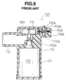
- the washer pump 101 has a motor chamber 111 enclosing a reversibly rotatable motor 102, a wash fluid suction pipe 112 communicating with a washer tank, not shown, a pump chamber 113 communicating with the suction pipe 112 and enclosing the impeller 103 fixed to the output shaft 102a of the motor 102, and a pump case 110 integrally provided with two wash fluid feed pipes 114A, 114B communicating with the pump chamber 113.
- the pump case 110 is integrally provided with the motor chamber 111, the suction pipe 112, the pump chamber 113, the two feed pipes 114A, 114B, two wash fluid delivery pipes 115A, 115B communicating with the two feed pipes 114A, 114B respectively, and two valve seats 116A, 116B each located between the two feed pipes 114A, 114B and the two delivery pipes 115A, 115B and facing each other. Also, mounted between the two valve seats 116A, 116B is an elastic membrane 104 which divides the space between the two valve seats 116A, 116B into one side space where the valve seat 116A is located and the other side space where the valve seat 116B is located.
- the washer pump 101 acts in such a manner that the rotation of the impeller 103 in one direction by the actuation of the motor 102 causes wash fluid to flow through the feed pipes 114A, 114B from the pump chamber 113 to one side space where the valve seat 116A is located and the other side space where the valve seat 116B is located respectively, with difference in pressure between wash fluid in the feed pipe 114A and wash fluid in the feed pipe 114B, and then one wash fluid passage is closed by the elastic membrane 104 at the valve seat 116A ( or the valve seat 116B) on low pressure side of the two feed pipes 114A, 114B while the other wash fluid passage is opened at the valve seat 116B (or the valve seat 116A) on high pressure side of the two feed pipes 114A, 114B, so that wash fluid is delivered from the delivery pipe 115B (or the delivery pipe 115A) communicating with the space where the valve seat 116B (or the valve seat 116A) is located.
- the above-mentioned prior arts are disclosed by
- the conventional washer pump 101 as described above is actuated in such a manner that the difference in pressure between the two feed pipes 114A, 114B causes the center portion of the elastic membrane 104 to move toward the valve seat 116A ( or the valve seat 116B) on the side of low pressure feed pipe 114A (or 114B) against the elastic force of the elastic membrane 104 to close one wash fluid passage at the valve seat 116A (or 116B), so that one of the two delivery pipes 115A, 115B is selected so as to deliver wash fluid.
- the force for moving the center portion of the elastic membrane 104 toward the valve seat on the low pressure side and the fore (or the sealing force) for keeping the wash fluid passage closed decrease by the elastic force of the elastic membrane 104, and the effective pressure area of the elastic membrane 104 decreases by the amount corresponding to the extension of the center portion thereof, and therefore the selection of the delivery pipe to be closed or opened, namely, the change-over of the delivery pipes 115A, 115B may not be performed completely, or may consume much time, and further leakage of wash fluid from the delivery pipe to be closed may occur, and furthermore when high viscous wash fluid is used, the washer pump is actuated at low temperatures, or the voltage in the battery supplying electric power to the motor 102 has dropped, the center portion of the elastic membrane 104 hardly moves in an axial direction. As a result, it becomes difficult to change over the delivery pipes 115A, 115B.
- the pump case 110 is integrally formed with the motor chamber 111, the suction pipe 112, the pump chamber 113, two feed pipes 114A, 114B, two delivery pipes 115A, 115B communicating with two feed pipes 114A, 114B respectively, and two valve seats 116A, 116B located between two feed pipes 114A, 114B and two delivery pipes 115A, 115B and facing each other, the pump case 110 enlarges to limit the degree of freedom for setting itself.
- an object of the present invention to provide an improved washer pump which can perform change-over of delivery directions of wash fluid completely and rapidly, thereby selectively supplying wash fluid through one selected from two delivery pipes, for example, when mounted in an automobile, to either front or rear windows without any leakage from the other delivery pipe under use of high viscous wash fluid, low temperature surroundings, or voltage dropped in a battery as well as under use of low or middle viscous wash fluid, ordinary temperature surroundings, or ordinary voltage.
- the washer pump comprises a pump body having two wash fluid feed pipes and feeding wash fluid through the two feed pipes with difference in pressure therebetween; and a valve mechanism having two wash fluid conduction pipes communicating with the two feed pipes, two wash fluid delivery pipes delivering wash fluid, two valve seats located between the two conduction pipes and the two delivery pipes respectively and facing each other, and a valve body movable between the two valve seats and having two seal portions engageable, namely, capable of making in contact with and departing from the two valve seats respectively, so that one wash fluid passage, which consists of the one feed pipe, the one conduction pipe, and the one delivery pipe, is closed at one of the two valve seats on low pressure side of the two feed pipes while the other wash fluid passage, which consists of the other feed pipe, the other conduction pipe, and the other delivery pipe, is opened at the other of the two valve seats on high pressure side of the two feed pipes.
- a valve mechanism having two wash fluid conduction pipes communicating with the two feed pipes, two wash fluid delivery pipes delivering wash fluid, two valve seats located between the two conduction pipes
- the valve body of the valve mechanism has a generally deep dish-shaped diaphragm including bottom, so that the bottom acts as as seal portion movable between the two valve seats and engageable the two valve seats respectively.
- the valve body of the valve mechanism has two generally deep dish-shaped diaphragms including bottoms.
- the bottoms are pushed in an axial direction to be connected each other, so that one of the bottoms acts as one side seal portion engageable with one of the two valve seats and the other of the bottoms acts as the other side seal portion engageable the other of the two valve seats.
- the bottoms of the two diaphragms may be connected each other through a piston member.
- the value mechanism includes a first valve case having one of the two conduction pipes and one of the two valve seats, a second valve case having the other of the two conduction pipes and the other of the two valve seats, and a valve body holder holding the valve body.
- the first and second valve cases are provided with a first valve case side engaging portion which engages one side of the valve body holder and a second valve case side engaging portion which engages the other side of the valve body holder with the first and second valve case side engaging portions facing each other and the seal portions of the valve body being located between the two valve seats.
- the piston member has two diaphragm connecting portions formed on both ends thereof and connected to each of the bottoms of the two diaphragms, a communicating passage passing through the two diaphragm connecting portions respectively, and a first air vent hole extending radialwardly from the communicating passage to the outer surface thereof
- the valve body holder has two diaphragm mounting portions formed on both sides thereof and mounting each of peripheries of the two diaphragms, and a second air vent hole passing through radialwardly.
- the pump body has a body case having the two feed pipes integrally formed therein, with the two feed pipes being provided with feed pipe side engaging portions respectively, and the conduction pipes of the first and second valve cases are provided with conduction pipe side engaging portions which engage the feed pipe side engaging portions respectively so that the feed pipe side engaging portions and the conduction pipe side engaging portions are engaged each other and the two feed pipes are connected to the two conduction pipes respectively.
- the pump body has a body case having the two feed pipes integrally formed therein, the two feed pipes are respectively connected to the two conduction pipes by using a tube.
- valve seats may be provided on end portions of the two conduction pipes respectively.
- valve seats may be provided on end portions of the two delivery pipes respectively.
- the washer pump comprises a pump body having a motor including an output shaft and reversibly rotatable, an impeller firmly connected to the output shaft, and a first and second wash fluid feed pipes communicating with a pump chamber enclosing the impeller; a first and second valve cases having a first and second wash fluid conduction pipes respectively connected to the first and second feed pipes and located so as to face each other, a first and second wash fluid delivery pipes respectively juxtaposed to the first and second conduction pipes and located so as to face each other, and a first and second valve seats integrally formed on the first and second conduction pipes; and a valve mechanism having a valve body holder annularly shaped and arranged between the first and second valve cases, and a valve body consisting of an annular projection fitted between at least one of the first and second valve cases and the valve body holder, an elastically-deforming portion extended from the annular projection, and a pair of seal portions extended from the elastically-deforming portion and arranged so as to respectively
- the valve body of the valve mechanism has a first annular projection fitted between the first valve case and the valve body holder, a first valve body forming member including a first seal portion engageable, namely, capable of coming in contact with and departing from the first valve seat formed on the first conduction pipe, a second annular projection fitted between the second valve case and the valve body holder, a second valve body forming member including a second seal portion engageable, namely, capable of coming in contact with and departing from the second valve seat formed on the second conduction pipe, with the first and second valve body forming members being provided with a first and second convex thick portions formed on opposite side surfaces with respect to the first and second seal portions, and a piston member including a first concave portion fitted to the first thick portion and a second concave portion fitted to the second thick portion, with the first and second concave portions being provided on both sides of the piston member.
- the washer pump comprises a pump body having a motor including an output shaft and reversibly rotatable, an impeller firmly connected to the output shaft, and a first and second wash fluid feed pipes communicating with a pump chamber enclosing the impeller; a first and second value cases having a first and second wash fluid conduction pipes respectively connected to the first and second feed pipes and located so as to face each other, a first and second wash fluid delivery pipes respectively juxtaposed to the first and second conduction pipes and located so as to face each other, and a first and second valve seats integrally formed on the first and second delivery pipes; and a valve mechanism having a valve body holder annularly shaped and arranged between the first and second valve cases, and a valve body consisting of an annular projection fitted between at least one of the first and second valve case and the valve body holder, an elastically-deforming portion extended from the annular projection, and a pair of seal portions extended from the elastically-deforming portion and arranged so as to respectively oppos
- the value body of the valve mechanism has a first annular projection fitted between the first valve case and the valve body holder, a first valve body forming member including a first seal portion engageable, namely, capable of coming in contact with and departing from the first value seat formed on the first delivery pipe, a second annular projection fitted between the second valve case and the valve body holder, a second valve body forming member including a second seal portion engageable, namely, capable of coming in contact with and departing from the second valve seat formed on the second delivery pipe, with the first and second valve body forming members being provided with a first and second convex thick portions respectively formed on opposite side surfaces with respect to the first and second seal portions, and a piston member including a first concave portion fitted to the first thick portion and a second concave portion fitted to the second thick portion, with the first and second concave portions being provided on both sides of the piston member.
- the piston member is provided with a communicating passage passing through the first and second concave portions and of a diameter smaller than that of the first and second concave portions, and a first air vent hole communicating with the communicating passage.
- valve body holder is provided with a second air vent hole communicating with the first air vent hole of the piston member.
- wash fluid is fed through the two feed pipes of the pump body and the two conduction pipes of the valve mechanism with difference in pressure to one side and the other side spaces which are divided by the valve body and in each of which each valve seat is situated, and then the seal portion of the valve body is moved toward the valve seat on low pressure side of the two conduction pipes to close one wash fluid passage while opening the other wash fluid passage, thereby delivering wash fluid from the delivery pipe communicating with the space where high pressure wash fluid flows.
- the seal portions of the valve body is movable between the two valve seats, so that the force (or the changing force) for moving the seal portions toward the valve seat on low pressure side and the force (or the sealing force) for keeping one wash fluid passage closed increase, and any leakage of wash fluid from the delivery pipe to be closed does not occur, and further the change-over of the delivery pipes is performed rapidly and completely.
- the washer pump is actuated at low temperatures, or the voltage in the battery for supplying electric power to the motor has dropped, the seal portions are moved smoothly between the two valve seats to assure the rapid and complete change-over of the delivery pipes.
- the bottom of the generally deep dish-shaped diaphragm serves as a seal portion. Therefore, if the bottom as a seal portion is pushed in the axial direction and then the intermediate portion between the bottom and the periphery are kept in a slacked configuration, the seal portion can be moved with little resistance by the amount corresponding to the slackness in the axial direction between the two valve seats with the effective pressure area being kept constant. As a result, the changing force and the sealing force increase, and any leakage of wash fluid from the delivery pipe to be closed does not occur, and further the change-over of the delivery pipes is performed rapidly and completely. Also, although high viscous wash fluid is used, the washer pump is actuated at low temperatures, or the voltage in the battery has dropped, the change-over of the delivery pipes is performed rapidly and completely.
- the two generally deep dish-shaped diaphragms are kept in such configurations that the intermediate portions between the bottoms and the peripheries are slacked, so that the respective bottoms of the two diaphragms connected each other, namely, one side and the other side seal portions are moved with little resistance by the amount corresponding to the slackness of the intermediate portions in the axial direction between the two value seats, and the respective effective pressure areas of both seal portions do not change by those movement.
- the changing force and the sealing force increase, so that any leakage of wash fluid from the delivery pipe to be closed does not occur, and the change-over of the delivery pipes is performed rapidly and completely.
- one side and the other side seal portions when wash fluid is not fed from the pump body, is always kept approximately at the neutral position, so that the movement stroke of both seal portions upon the change-over of the delivery pipes becomes short, and the change-over is performed more rapidly.
- one and the other side seal portions are moved stably between the two value seats, so that the changeover of the delivery pipes is performed more completely.
- the first and second valve cases and the value body holder are assembled one another in such a manner that the first valve case side engaging portion of the first valve case and the second valve case side engaging portion of the second valve case are opposed each other with the valve body being arranged therebetween, and then one side of the valve body holder is engaged with the first value case side engaging portion and the other side of the valve body holder is engaged with the second valve case side engaging portion.
- the seal portions of the valve body are located between the two valve seats, consequently, the seal portions are arranged readily between the two value seats, and the maintenance of the valve mechanism is performed readily.
- the air existing within the communicating passage of the piston member is evacuated through the respective air vent holes of the piston member and the valve body holder, and at the same time the air existing between the two diaphragms is evacuated through the air vent hole of the valve body holder, so that the respective bottoms of the two diaphragms are pulled in both diaphragm connecting portions in the axial direction to be fixed therein, and the respective peripheries of the two diaphragms are fixed in the diaphragm mounting portions.
- closing the air vent hole of the valve body holder causes the intermediate portions between the bottoms and the peripheries of the two generally deep dish-shaped diaphragms to be kept in s
- the maintenance of the pump body and the valve mechanism is performed readily.
- the only one having broken down may be replaced to reduce the repair cost.
- the pump body is arranged apart from the valve mechanism, so that the degree of freedom for arrangement increases.
- the pressure of wash fluid fed through the two conduction pipes directly acts on the seal portions of the valve body in tile axial direction, so that the seal portions are moved very smoothly.
- the seal portion of the valve body has attached to the valve seat provided on the end portion of the delivery pipe, the pressure of wash fluid from the pump body through the conduction pipe acts on the valve body to prevent the changing force from becoming very small, thereby preventing the seal portion of the valve body from keeping the wash fluid passage closed at the valve seat.
- the seal portions are moved with little resistance by the amount corresponding to deformation of the elastically-deforming portions in the axial direction between the two value seats with the effective pressure areas thereof being kept constant, so that the changing force and the sealing force increase. Therefor, any leakage of wash fluid from the delivery pipe to be closed does not occur, and the change-over of the delivery pipes is performed rapidly and completely.
- the pressure of wash fluid fed through the two conduction pipes directly acts on the seal portions of the valve body in the axial direction, thereby moving the seal portions very smoothly.
- seal portions are arranged between the two valve seats readily, and the valve body is provided with elastically-deforming portions preformed, and therefore it is not necessary to form the elastically-deforming portions manually, so that man-hour for assembling is reduced, and the maintenance of the valve mechanism is performed readily.
- the changing force and the sealing force increase, so that any leakage of wash fluid from the delivery pipe to be closed does not occur, and the change-over of the delivery pipes is performed rapidly and completely.
- the valve body with the first and second seal portions when wash fluid is not fed from the pump body, is always kept approximately at the neutral position between the two valve seats, so that the movement stroke of both seal portions upon the change-over becomes short, and the change-over is performed more rapidly.
- the piston member is provided between the first and second valve body forming members, the first and second seal portions, when wash fluid is fed from the pump body, are moved stably, thereby performing the change-over of the delivery pipes more completely.
- the valve body is provided with elastically-deforming portions, the seal portions are moved with little resistance between the two valve seats, and the effective pressure areas of the seal portions does not change. Therefore, the changing force and the sealing force increase and the change-over of the delivery pipes is performed rapidly and completely.
- the seal portion of the valve body has attached to the valve seat provided on the end of the delivery pipe, because the pressure of wash fluid fed through the conduction pipe from the pump body acts on the valve body, the changing force does not become very small, thereby preventing the seal portion from keeping the wash fluid passage closed at the valve seat.
- seal portions are arranged between the two valve seats readily and the valve body is provided with elastically deforming portions preformed, it is not necessary to form the elastically-deforming portions manually, and therefore man-hour for assembling is reduced and the maintenance of the valve mechanism is performed readily.
- the changing force and the sealing force increase, so that the change-over of the delivery pipes is performed rapidly and completely.
- the valve body with the first and second seal portions when wash fluid is not fed from the pump body, is always kept approximately at the neutral position between the two valve seats, so that the movement stroke of both seal portions upon the change-over becomes short and the change-over is performed more rapidly.
- the piston member is provided between the first and second valve body forming members, the first and second seal portions, when wash fluid is fed from the pump body, are moved stably, thereby performing the change-over of the delivery pipes more completely.
- the air existing within the communicating passage of the piston member is evacuated through the first air vent hole, so that the respective thick portions of the two valve body forming members are pulled in both concave portions of the piston member to be fixed therein.
- the air existing within the communicating passage of the piston member is evacuated through the respective air vent hole of the piston member and the valve body holder and, at the same time, the air existing between the two valve body forming members is evacuated through the second air vent hole of the valve body holder.
- closing the second air vent hole of the valve body holder causes the respective thick portions of the two valve body forming members to be firmly fixed in both concave portions of the piston member respectively, and causes the respective annular projections of the two valve body forming members to be firmly fixed between the valve cases and the valve body holder.
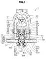
- Fig.1 is a horizontal sectional view along the wash fluid feed pipes of the pump body showing one embodiment of a washer pump according to the present invention.
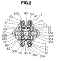
- Fig.2 is a vertical sectional view along the valve seats of the washer pump seen in Fig.1.
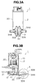
- Fig.3a is a front view of the washer pump seen in Fig.1.
- Fig.3b is a side sectional view of the washer pump seen in Fig.1.
- Fig.4 is an exploded perspective view of the diaphragms as a valve body forming members and the piston member of the valve mechanism regarding the washer pump seen in Fig.1.
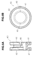
- Fig.5a is a fragmentary sectional and front view of the valve body holder supporting the valve body of the valve mechanism regarding the washer pump seen in Fig.1.
- Fig.5b is a side view of the valve body holder supporting the valve body of the valve mechanism regarding the washer pump seen in Fig.1.
- Fig.6 is a horizontal sectional view along the wash fluid feed pipes showing another embodiment of a washer pump according to the present invention.
- Fig.7 is a side view showing still another embodiment using a tube of a washer pump according to the present invention.
- Fig.8 is a perspective view of the deep dish-shaped diaphragm showing another embodiment of a valve body forming member adapted to a washer pump according to the present invention.
- Fig.9 is a vertical sectional view showing a washer pump according to the prior art.
- Fig.10 is a horizontal sectional view along one wash fluid feed pipe of the washer pump seen in Fig.9.
- Figs.1-6 show washer pumps according to the present invention.
- the washer pump 1 has a pump body 2 and a valve mechanism 3.
- the pump body 2 has a body case 20 enclosing a reversibly rotatable motor 10.
- the body case 20 is integrally provided with a wash fluid suction pipe 21 communicating with a washer tank, not shown, a pump chamber 22 communicating with the suction pipe 21 and enclosing an impeller 12 fixed to the output shaft 11 of the motor 10, and two wash fluid feed pipes 23 (23A, 23B) communicating with the pump chamber 22, as shown by Fig.1.
- the valve mechanism 3 on the other hand, as shown by Fig. 2, has two wash fluid conduction pipes 33 (33A, 33B) communicating with the feed pipes 23 (23A, 23B) respectively, two wash fluid delivery pipes 34 (34A, 34B) delivering wash fluid, two valve seats 35 (a first valve seat 35A and a second valve seat 35B) respectively formed at the end portions of the conduction pipes 33 (33A, 33B).
- first wash fluid conduction pipe 33A of the conduction pipes 33 (33A, 33B) and one (first wash fluid delivery pipe) 34A of the delivery pipes 34 (34A, 34B) are integral-formed in a first valve case 30A
- second wash fluid conduction pipe 33B and the other (second wash fluid delivery pipe) 34B are integral-formed in a second valve case 30B
- first and second valve cases 30A, 30B are arranged so as to oppose the valve seats 35 (35A, 35B) respectively.
- the valve mechanism 3 also, has a valve body 4 located between two valve seats 35 and comprising two diaphragms 5, 5 (first and second valve body forming members).
- the diaphragms 5, 5 are supported on a valve body holder 40 with the annular projections 51, 51 provided at the peripheries thereof being respectively fitted into the annular grooves 41, 41 (diaphragm mounting portions) provided on both side surfaces of the generally ring-shaped value body holder 40 shown by Fig.5.
- valve body 4 is assembled in such a manner that one side of the valve body holder 40 is fitted into the first valve case side engaging portion 36A provided on the first valve case 30A with one diaphragm 5 being opposed to the valve seat 35A, and the other side of the valve body holder 40 is fitted into the second valve case side engaging portion 36B provided on the second valve case 30B with the other diaphragm 5 being opposed to the valve seat 35B, and further, the annular projections 42, 42 provided on both fitting portions of the valve body holder 40 are engaged with the annular grooves 37A, 37B provided on the first and second valve case side fitting portions 36A, 36B, so that the valve body 4 is firmly connected to the first and second valve case 30A, 30B respectively.
- the diaphragms 5, 5, as shown by Fig.4 are provided with the annular projections 51, 51 above described, the elastically-deforming portions 54, 54 preformed so as to be slacked toward the centers of the annular projections 51, 51, and the thick portions 52, 52 provided on the respective center areas thereof.
- the respective thick portions 52, 52 are fitted into the respective concave portions 61, 61 (diaphragm connecting portions) provided on both end portions of the piston member 6 respectively to be connected each other with the piston member 6 being sandwiched therebetween, whereby the opposite side surface of one of the thick portions 52 acts as one side seal portion (first seal portion) 53A engageable with one 35A of the valve seats 35, and the opposite side surface of the other of the thick portions 52 acts as the other side seal portion (second seal portion) 53B engageable with the other 35B of the valve seats 35.
- the piston member 6 has the concave portions 61, 61 above described, a communicating passage 62 provided along the center axis of the piston member 6 and passing through the concave portions 61, 61, and an air vent hole (first air vent hole) 63 extending radialwardly from the communicating passage 62 and opening at the outer cylindrical surface.
- the valve body holder 40 is provided with an air vent hole (second air vent hole) 43 passing through itself in the radial direction.
- the air existing within the communicating passage 62 of the piston member 6 is evacuated through the respective air vent hole 63, 43 of the piston member 6 and the valve body holder 40, and at the same time, the air existing between the diaphragms 5, 5 is evacuated through the air vent hole 43 of the valve body holder 40, whereby the respective thick portions 52, 52 of the diaphragms 5, 5 are pulled into the respective concave portions 61, 61 to firmly fixed therein.
- annular projections feed pipe side engaging portions
- annular grooves 39 conduction pipe side engaging portions
- the washer pump 1, as shown by Fig.1, is actuated in such a manner that the impeller 12 is rotated, for example, in the clockwise direction by driving the motor 10 in the pump body 2, and wash fluid sucked into the pump chamber 22 from the washer tank through the suction pipe 21 is fed through the feed pipes 23 and the conduction pipes 33 of the valve mechanism 3 to one side space where the valve seat 35A is located and the other side space where the valve seat 35B is located, with the difference in pressure, whereby both seal portions 53A, 53B of the valve body 4 are moved with the piston member 6 toward the valve set 35B on the end portion of the conduction pipe 33B communicating with the feed pipe 34B feeding low pressure wash fluid to close the one wash fluid passage at the valve seat 35B while opening the other wash fluid passage at the valve seat 35A on the end portion of the conduction pipe 33A communicating with the feed pipe 34A feeding high pressure wash fluid and then high pressure wash fluid is delivered from the feed pipe 34A to a desired area.
- the force (the changing force) for moving the seal portions 53A, 53B toward the low pressure side valve seat 35 (35B in Fig.1) and the force (sealing force) for keeping one wash fluid passage on low pressure side closed increase, so that any leakage of wash fluid from the delivery pipe 34 to be closed (34B in Fig.1) does not arise, and the change-over of the delivery pipes 34 can be performed rapidly and completely.
- the valve body 4 with both seal portions 53A, 53B when wash fluid is not fed from the pump body 2, always stops at the neutral position between the valve seats 35A, 35B, whereby the movement stroke of both seal portions 53A, 53B upon the change-over of the delivery pipes 34 becomes short and then the change-over of the delivery pipes 34 can be performed rapidly and completely.
- both seal portions 53A, 53B can be moved stably between the valve seats 35 (35A, 35B), and therefore the change-over of the delivery pipes 34 can be performed more completely.
- the respective valve seats 35 are provided on the end portions of the conduction pipes 33, so that the pressure of wash fluid fed through the conduction pipes 33 directly acts on both seal portions 53A, 53B of the valve body 4 in the axial direction to move both seal portions very smoothly.
- the first valve case side engaging portion 36A of the first valve case 30A and the second valve case side engaging portion 36B of the second valve case 30B are opposed each other with the valve body 4 being arranged therebetween, and the one side of the valve body holder 40 is fitted into the first valve case side engaging portion 36A and the other side of the valve body holder 40 is fitted into the second valve case side engaging portion 36B, further, the respective annular projections 42, 42 of the valve body holder 40 are engaged with the respective annular grooves 37A, 37B of the first and second valve case side engaging portions 36A, 36B, so that the assembling of the first and second valve case 30A, 30B and the valve body holder 40 is accomplished.
- both seal portions 53A, 53B of the valve body 4 are situated between the valve seats 35 (35A, 35B), both seal portions 53A 53B can be arranged between the valve seats 35 (35A, 35B) readily, and the valve mechanism 3 can be maintained readily.
- the diaphragms 5, 5 of as a valve body forming member are provided with the elastically-deforming portions 54 with the slacked configurations, upon mounted to the piston member 6, the elastically-deforming portions 54 do not need to be formed manually and therefore the man-hour for assembling can be reduced.
- the respective end portions of the feed pipes 23 (23A, 23B) of the pump body 2 are fitted into the respective large openings 38 of the conduction pipes 33 (33A, 33B) of the valve case 30A, 30B, and the respective annular projections 29 on the feed pipes 23 (23A, 23B) are engaged with the annular grooves 39 on the conduction pipes 33 (33A, 33B), so that the first and second valve case 30A, 30B of the valve mechanism 3 are mounted to the body case 20, and therefore the pump body 2 and the valve mechanism 3 can be maintained readily.
- the only one having broken down can be replaced. As a result, the repair cost can be reduced.
- Fig.6 shows a still another embodiment of a washer pump according to the present invention.
- the washer pump 71 regarding this embodiment is different from the washer pump 1 regarding the above-mentioned embodiment in that two valve seats 75 (75A, 75B) are provided on the respective end portions of the delivery pipes 74 (74A, 74B) of the first and second valve cases 70A, 70B.
- Other constitutions of the washer pump 71 are identical with those of the washer pump 1 regarding the above-mentioned embodiment.
- Fig.7 shows a still another embodiment of a washer pump according to the present invention.
- the washer pump 81 regarding this embodiment is different from the washer pump 1 regarding the fore-mentioned embodiment in that the feed pipes 23 of the body case 20 are connected to the conduction pipes 33 of the first and second valve cases 30A, 30B respectively by using a tube 82.
- Other constitutions of the washer pump 81 are identical with those of the washer pump 1 regarding the afore-mentioned embodiment.
- the pump body 2 and the valve mechanism 3 can be arranged so as to be apart from each other, and therefore the degree of freedom for arrangement can be increased.
- each valve body forming member as shown by Fig.8 (one of them is shown), may be formed as a generally deep dish-shaped diaphragm 56 having an annular projection 57 at the periphery and a thick portion 58 at the bottom.
- the thick portions 58 are pushed in the axial direction to be fitted into the concave portions 61 of the piston member 6, and the air existing within the communicating passage 62 of the piston member 6 is evacuated through the respective air vent hole 63, 43 of the piston member 6 and the valve body case 40, and further the air existing between the diaphragms 56 is evacuated through the air vent hole 43 of the valve body holder 40, and therefore the respective intermediate portions between the bottoms and the peripheries of the diaphragms 56 can be slacked to be formed as elastically-deforming portions.
- the advantageous effects obtained are as follows:
- the seal portions of the valve body con be moved between two valve seats with little resistance, and therefore the force (changing force) for moving the seal portions toward the valve seat on the low pressure side and the force (sealing force) for keeping one wash fluid passage on the low pressure side closed can be increased.
- the washer pump is actuated at low temperatures, or the voltage in the battery supplying electric power to the washer pump has dropped, the wash fluid passage in one conduction pipe on the low pressure side is closed completely at the valve seat, whereby any leakage of wash fluid from one conduction pipe to be closed does not arise, and the change-over of the delivery pipes can be performed rapidly and completely.
- the changing force and the sealing force can be increased, and even though high viscous wash fluid is used, the washer pump is actuated at low temperatures, or the voltage in the battery has dropped, any leakage of wash fluid from the delivery pipe to be closed does not arise, and the change-over of the delivery pipes can be performed rapidly and completely.
- valve body with one side and the other side seal portions when wash fluid is fed from the pump body, is kept at the neutral position between two valve seats, and therefore the movement stroke of both seal portions upon the change-over of the delivery pipes becomes short, whereby the change-over is performed more rapidly.
- first and second valve cases and the valve body holder can be assembled one another in such a manner that the first valve case side engaging portion of the first valve case and the second valve case side engaging portion of the second valve case are opposed each other with the valve body being arranged therebetween, and then one side of the valve body holder is engaged with the first valve case side engaging portion and the other side of the valve body holder is engaged with the second valve case side engaging portion.
- the maintenance of the pump body and the valve mechanism can be performed readily.
- the only one having broken down can be replaced, and therefore the repair cost can be reduced.
- the pump body and the valve mechanism can be arranged so as to be apart from each other, and therefore the degree of freedom for arrangement can be increased.
- seal portions can be moved with little resistance by the amount corresponding to the deformation of the elastically-deforming portions in the axial direction keeping the wash fluid passage closed at the valve seat on the low pressure side. Further, the seal portions of the valve body can be arranged or located between two valve seats readily. Furthermore, since the valve body is provided with elastically-deforming portions preformed, it is not necessary to form the elastically-deforming portions manually, and therefore man-hour for assembling can be reduced, and further the maintenance of the valve mechanism can be carried out readily.
- advantageous effects obtained are as follows: As like the washer pump above-mentioned, the changing force and the sealing force are increased, and therefore the change-over of the delivery pipes can be performed rapidly and completely.
- the valve body with the first and second seal portions when wash fluid is not fed from the pump body, is always situated or kept approximately at the neutral position between two valve seats, the movement distance or stroke of both seal portions upon the change-over becomes short, and therefore the change-over can be carried out more rapidly.
- the piston member is provided between the first and second valve body forming members, the first and second seal portions can be moved stably between two valve seats, and therefore the change-over of the delivery pipes can be carried out more completely.
Landscapes
- Engineering & Computer Science (AREA)
- Mechanical Engineering (AREA)
- General Engineering & Computer Science (AREA)
- Water Supply & Treatment (AREA)
- Physics & Mathematics (AREA)
- Fluid Mechanics (AREA)
- Details Of Reciprocating Pumps (AREA)
- Structures Of Non-Positive Displacement Pumps (AREA)
Priority Applications (3)
| Application Number | Priority Date | Filing Date | Title |
|---|---|---|---|
| JP8004196A JPH09188227A (ja) | 1996-01-12 | 1996-01-12 | ウォッシャポンプ |
| US08/834,526 US5934872A (en) | 1996-01-12 | 1997-04-04 | Washer pump for selectively supplying wash fluid to two areas |
| EP97105804A EP0870656A1 (de) | 1996-01-12 | 1997-04-08 | Waschpumpe zur wahlweisen Versorgung zweier Flächen mit Waschflüssigkeit |
Applications Claiming Priority (3)
| Application Number | Priority Date | Filing Date | Title |
|---|---|---|---|
| JP8004196A JPH09188227A (ja) | 1996-01-12 | 1996-01-12 | ウォッシャポンプ |
| US08/834,526 US5934872A (en) | 1996-01-12 | 1997-04-04 | Washer pump for selectively supplying wash fluid to two areas |
| EP97105804A EP0870656A1 (de) | 1996-01-12 | 1997-04-08 | Waschpumpe zur wahlweisen Versorgung zweier Flächen mit Waschflüssigkeit |
Publications (1)
| Publication Number | Publication Date |
|---|---|
| EP0870656A1 true EP0870656A1 (de) | 1998-10-14 |
Family
ID=27238182
Family Applications (1)
| Application Number | Title | Priority Date | Filing Date |
|---|---|---|---|
| EP97105804A Withdrawn EP0870656A1 (de) | 1996-01-12 | 1997-04-08 | Waschpumpe zur wahlweisen Versorgung zweier Flächen mit Waschflüssigkeit |
Country Status (3)
| Country | Link |
|---|---|
| US (1) | US5934872A (de) |
| EP (1) | EP0870656A1 (de) |
| JP (1) | JPH09188227A (de) |
Cited By (1)
| Publication number | Priority date | Publication date | Assignee | Title |
|---|---|---|---|---|
| DE10061013B4 (de) * | 2000-12-08 | 2006-12-28 | Siemens Ag | Fördereinrichtung für ein Kraftfahrzeug und Vorratsbehälter für eine Fördereinrichtung |
Families Citing this family (14)
| Publication number | Priority date | Publication date | Assignee | Title |
|---|---|---|---|---|
| US6675989B1 (en) | 2001-06-28 | 2004-01-13 | Valeo Electrical Systems, Inc. | Windshield washer pump with integrated fluid level sensor |
| US6530758B1 (en) * | 2001-06-28 | 2003-03-11 | Valeo Electrical Systems, Inc. | Composite fluid control membrane for windshield washer pump and method of manufacturing same |
| DE10262093B4 (de) | 2002-05-08 | 2010-04-15 | Fico Transpar, S.A. | Pumpenanordnung für Reinigungssysteme, insbesondere für Kraftfahrzeuge |
| JP4527352B2 (ja) * | 2002-12-16 | 2010-08-18 | アスモ株式会社 | ポンプ装置及び車両用ウォッシャポンプ装置 |
| JP2004224214A (ja) * | 2003-01-23 | 2004-08-12 | Jidosha Denki Kogyo Co Ltd | ウォッシャポンプ |
| DE102007052644A1 (de) * | 2007-11-05 | 2009-05-07 | Continental Automotive Gmbh | Scheibenreinigungsanlage für Scheiben eines Kraftfahrzeuges |
| KR101027631B1 (ko) * | 2009-06-19 | 2011-04-07 | 주식회사 캐프 | 자동차용 워셔액 펌프 |
| KR101813742B1 (ko) * | 2010-10-05 | 2017-12-29 | 가부시키가이샤 니프코 | 유체분배밸브 및 이것을 구비한 유체공급 시스템 및 그 제어 방법 |
| CN102121477B (zh) * | 2011-03-31 | 2012-12-26 | 宁波巨神制泵实业有限公司 | 大型潜水排污泵 |
| JP6267882B2 (ja) * | 2013-07-08 | 2018-01-24 | 株式会社ミツバ | 車両用ウォッシャバルブ装置及び車両用ウォッシャ装置 |
| WO2017208732A1 (ja) * | 2016-05-31 | 2017-12-07 | 株式会社ミツバ | ウォッシャポンプ |
| JP6545125B2 (ja) * | 2016-05-31 | 2019-07-17 | 株式会社ミツバ | ウォッシャポンプ |
| KR102555267B1 (ko) * | 2016-06-13 | 2023-07-14 | 엘지전자 주식회사 | 의류처리장치용 배수펌프 |
| EP3267042B1 (de) * | 2016-07-08 | 2020-01-15 | Grundfos Holding A/S | Pumpenaggregat |
Citations (4)
| Publication number | Priority date | Publication date | Assignee | Title |
|---|---|---|---|---|
| EP0145672A2 (de) * | 1983-10-14 | 1985-06-19 | FOREDIT S.p.A. | Verteileinrichtung für zweiseitige Pumpen |
| GB2202133A (en) * | 1987-03-14 | 1988-09-21 | Bosch Gmbh Robert | Windscreen washer pump and valve assembly |
| FR2654470A1 (fr) * | 1989-11-10 | 1991-05-17 | Seim Ind | Pompe centrifuge bidirectionnelle. |
| FR2703409A1 (fr) * | 1993-04-02 | 1994-10-07 | Seim Ind | Pompe centrifuge bi-directionnelle. |
Family Cites Families (6)
| Publication number | Priority date | Publication date | Assignee | Title |
|---|---|---|---|---|
| GB8603367D0 (en) * | 1986-02-11 | 1986-03-19 | Lucas Elect Electron Syst | Fluid pump |
| IT1210354B (it) * | 1987-03-17 | 1989-09-14 | Nuova Sme S P A | Pompa a doppia mandata selezionabile |
| US4824332A (en) * | 1988-03-07 | 1989-04-25 | Mccord Winn Textron Inc. | Reversible pump assembly |
| US4900235A (en) * | 1988-03-07 | 1990-02-13 | Mccord Winn Textron Inc. | Reversible pump assembly |
| JPH01176792U (de) * | 1988-06-03 | 1989-12-18 | ||
| US5344293A (en) * | 1990-12-21 | 1994-09-06 | Transpar Iberica S.A. | Double diaphragm leakproof sealing device for electric windscreen washer pumps |
-
1996
- 1996-01-12 JP JP8004196A patent/JPH09188227A/ja active Pending
-
1997
- 1997-04-04 US US08/834,526 patent/US5934872A/en not_active Expired - Fee Related
- 1997-04-08 EP EP97105804A patent/EP0870656A1/de not_active Withdrawn
Patent Citations (4)
| Publication number | Priority date | Publication date | Assignee | Title |
|---|---|---|---|---|
| EP0145672A2 (de) * | 1983-10-14 | 1985-06-19 | FOREDIT S.p.A. | Verteileinrichtung für zweiseitige Pumpen |
| GB2202133A (en) * | 1987-03-14 | 1988-09-21 | Bosch Gmbh Robert | Windscreen washer pump and valve assembly |
| FR2654470A1 (fr) * | 1989-11-10 | 1991-05-17 | Seim Ind | Pompe centrifuge bidirectionnelle. |
| FR2703409A1 (fr) * | 1993-04-02 | 1994-10-07 | Seim Ind | Pompe centrifuge bi-directionnelle. |
Cited By (1)
| Publication number | Priority date | Publication date | Assignee | Title |
|---|---|---|---|---|
| DE10061013B4 (de) * | 2000-12-08 | 2006-12-28 | Siemens Ag | Fördereinrichtung für ein Kraftfahrzeug und Vorratsbehälter für eine Fördereinrichtung |
Also Published As
| Publication number | Publication date |
|---|---|
| US5934872A (en) | 1999-08-10 |
| JPH09188227A (ja) | 1997-07-22 |
Similar Documents
| Publication | Publication Date | Title |
|---|---|---|
| US5934872A (en) | Washer pump for selectively supplying wash fluid to two areas | |
| EP1308622B1 (de) | Membranpumpe | |
| US4176823A (en) | Butterfly valve | |
| EP1186756B1 (de) | Druckempfindliches Ventil für einen Abgasschalldämpfer und Montageverfahren dazu | |
| CN111828687A (zh) | 一种控制阀 | |
| US6003835A (en) | Diaphragm valve | |
| CN110966434B (zh) | 球阀 | |
| US5374032A (en) | Butterfly valve assembly | |
| JP3925096B2 (ja) | 流量制御弁 | |
| KR100430169B1 (ko) | 정압 레귤레이터 | |
| JPH09229214A (ja) | 四方切換弁 | |
| JP2002285966A (ja) | 制御弁フィルタ | |
| EP3660309B1 (de) | Membranpumpe | |
| CN110094520B (zh) | 电动阀 | |
| CN110094519B (zh) | 电动阀 | |
| EP1134469A3 (de) | Mehrwegeschieber mit Aufsatzbefestigungselementen | |
| JPH09207795A (ja) | 油圧パワーステアリング装置 | |
| CN217355689U (zh) | 小型逆止压力开关 | |
| JP2566494Y2 (ja) | 斜板式油圧ポンプ・モータ | |
| KR102244637B1 (ko) | 트랜스퍼 케이스 | |
| US5704394A (en) | Vacuum valve with integrated selector plate | |
| JP3138806B2 (ja) | 制御油圧出力装置 | |
| EP1195521A2 (de) | Taumelscheibenverdichtergehäuse | |
| JPH0579142U (ja) | スプール弁 | |
| WO1995009306A1 (fr) | Amortisseur pour servo-soupape hydraulique |
Legal Events
| Date | Code | Title | Description |
|---|---|---|---|
| PUAI | Public reference made under article 153(3) epc to a published international application that has entered the european phase |
Free format text: ORIGINAL CODE: 0009012 |
|
| AK | Designated contracting states |
Kind code of ref document: A1 Designated state(s): DE FR GB |
|
| AX | Request for extension of the european patent |
Free format text: AL;LT;LV;RO;SI |
|
| 17P | Request for examination filed |
Effective date: 19990210 |
|
| AKX | Designation fees paid |
Free format text: DE FR GB |
|
| 17Q | First examination report despatched |
Effective date: 20010316 |
|
| STAA | Information on the status of an ep patent application or granted ep patent |
Free format text: STATUS: THE APPLICATION IS DEEMED TO BE WITHDRAWN |
|
| 18D | Application deemed to be withdrawn |
Effective date: 20020514 |