EP0869382B1 - Projection optical system - Google Patents
Projection optical system Download PDFInfo
- Publication number
- EP0869382B1 EP0869382B1 EP98106068A EP98106068A EP0869382B1 EP 0869382 B1 EP0869382 B1 EP 0869382B1 EP 98106068 A EP98106068 A EP 98106068A EP 98106068 A EP98106068 A EP 98106068A EP 0869382 B1 EP0869382 B1 EP 0869382B1
- Authority
- EP
- European Patent Office
- Prior art keywords
- lens group
- lens
- fluorite
- lens elements
- sio
- Prior art date
- Legal status (The legal status is an assumption and is not a legal conclusion. Google has not performed a legal analysis and makes no representation as to the accuracy of the status listed.)
- Expired - Lifetime
Links
- 230000003287 optical effect Effects 0.000 title claims description 45
- VYPSYNLAJGMNEJ-UHFFFAOYSA-N silicon dioxide Inorganic materials O=[Si]=O VYPSYNLAJGMNEJ-UHFFFAOYSA-N 0.000 claims description 226
- WUKWITHWXAAZEY-UHFFFAOYSA-L calcium difluoride Chemical compound [F-].[F-].[Ca+2] WUKWITHWXAAZEY-UHFFFAOYSA-L 0.000 claims description 105
- 239000010436 fluorite Substances 0.000 claims description 69
- 239000010453 quartz Substances 0.000 claims description 38
- 239000002131 composite material Substances 0.000 claims description 13
- 239000000463 material Substances 0.000 claims description 8
- 239000011521 glass Substances 0.000 claims description 7
- 230000004075 alteration Effects 0.000 description 100
- 229910052681 coesite Inorganic materials 0.000 description 93
- 229910052906 cristobalite Inorganic materials 0.000 description 93
- 239000000377 silicon dioxide Substances 0.000 description 93
- 229910052682 stishovite Inorganic materials 0.000 description 93
- 229910052905 tridymite Inorganic materials 0.000 description 93
- 229910001634 calcium fluoride Inorganic materials 0.000 description 36
- 206010010071 Coma Diseases 0.000 description 13
- 238000001228 spectrum Methods 0.000 description 10
- 235000012431 wafers Nutrition 0.000 description 10
- 239000006185 dispersion Substances 0.000 description 9
- 201000009310 astigmatism Diseases 0.000 description 6
- 238000005286 illumination Methods 0.000 description 5
- 238000003384 imaging method Methods 0.000 description 4
- 238000000034 method Methods 0.000 description 4
- 230000000694 effects Effects 0.000 description 2
- 230000005499 meniscus Effects 0.000 description 2
- 239000000758 substrate Substances 0.000 description 2
- 241000276498 Pollachius virens Species 0.000 description 1
- XUIMIQQOPSSXEZ-UHFFFAOYSA-N Silicon Chemical compound [Si] XUIMIQQOPSSXEZ-UHFFFAOYSA-N 0.000 description 1
- 230000003247 decreasing effect Effects 0.000 description 1
- 238000004519 manufacturing process Methods 0.000 description 1
- QSHDDOUJBYECFT-UHFFFAOYSA-N mercury Chemical compound [Hg] QSHDDOUJBYECFT-UHFFFAOYSA-N 0.000 description 1
- 229910052753 mercury Inorganic materials 0.000 description 1
- 239000000203 mixture Substances 0.000 description 1
- 239000004065 semiconductor Substances 0.000 description 1
- 229910052710 silicon Inorganic materials 0.000 description 1
- 239000010703 silicon Substances 0.000 description 1
- 238000002834 transmittance Methods 0.000 description 1
Images


Classifications
-
- G—PHYSICS
- G02—OPTICS
- G02B—OPTICAL ELEMENTS, SYSTEMS OR APPARATUS
- G02B9/00—Optical objectives characterised both by the number of the components and their arrangements according to their sign, i.e. + or -
- G02B9/12—Optical objectives characterised both by the number of the components and their arrangements according to their sign, i.e. + or - having three components only
-
- G—PHYSICS
- G02—OPTICS
- G02B—OPTICAL ELEMENTS, SYSTEMS OR APPARATUS
- G02B13/00—Optical objectives specially designed for the purposes specified below
Definitions
- the present invention relates to a projection optical system and more particularly to a reducing refraction projection optical system for optically projecting on semiconductor wafers in an exposure device at high resolution preferably with compensation for both chromatic aberrations and other monochromatic aberrations accomplished at the same time.
- the present invention provides a projection optical system in which both problems of partial compensation of chromatic aberrations and compensation of other monochromatic aberrations may be handled simultaneously. Therefore, the range of spectrum of a laser light source for exposure can be set wider so that the throughput is improved.
- a projection optical system of the present invention comprises:
- the projection optical system of the present invention comprises from the objective end:
- the projection optical system should satisfy the following conditions:
- This arrangement of the lens groups in order of positive/negative/positive power allows the optical system to be telecentric at both-ends, that is, telecentric with respect to both the objective and the image ends.
- the Petzval sum which profoundly relates to "image planarity" in order to accomplish high resolution in the wide range of exposure areas, can be effectively compensated.
- the reason for employing an optical system which is the telecentric at the image and objective ends is to make this optical system less affected by fluctuation in magnification due to errors in the optical axis direction during exposure and less affected to distortions of silicon wafers on the image plane or to distortions of the reticle on the objective plane.
- the above equation (1) is a condition for maintaining telecentricity. When the upper limit of the condition is exceeded, it is difficult to maintain excellent telecentricity so that excessive effects on focusing errors result.
- equation (2) defines an appropriate range for the ratios of the composite power of only fluorite lens elements in the third lens group G3 to the power of the third lens group.
- AXi Q i ⁇ h i 2 ⁇ [ ⁇ n i / n i - ⁇ n i-1 / n i-1 ]
- the aberration coefficient of chromatic aberrations AXi is often used in each of the surfaces in an optical system as a means to understand the structure of occurrence and compensation of chromatic aberrations.
- contribution of each of the surfaces to axial chromatic aberrations is proportional to dispersion of a glass material; it is also proportional to the squared number of its paraxial ray height. Therefore, in order to compensate chromatic aberration effectively, it is preferable to use a fluorite lens on the low dispersion side as a positive power lens element positioned high in the paraxial ray height for preventing occurrence of chromatic aberration.
- the paraxial ray height is higher in the third lens group G3, which is in the image end, than in the first lens group, which is in the objective end.
- the present invention intends to focus on the power ratios of the fluorite lens elements in the third lens group in order to accomplish effective compensation of chromatic aberration.
- the upper limit is larger than 1.
- a parameter of equation (2) is larger than 1, it indicates that the composite power of the fluorite lens elements is larger than the power of the third lens group; that is, the third lens group comprises quartz lens elements with negative power.
- the second lens group G2 having negative power has a structure such that the paraxial ray height is low, which is convenient for compensation of the Petzval sum.
- contribution of chromatic aberrations compensation by the quartz lens elements with negative power in the second lens group G2 is less effective. Therefore, by using the paraxial ray height, the fluorite lens elements with positive power are positioned within the third lens group G3 such that occurrence of chromatic aberrations is prevented and at the same time, the quartz lens elements with negative power are positioned within the third lens group G3 such that chromatic aberrations are effectively compensated.
- the composite power of the fluorite lens elements in the third lens group should preferably be within the range defined in equation (2).
- Equation (2) The composite focal length of the fluorite lens elements in the third lens group f 3c as shown in equation (2) is defined by equation (B) below: where:
- a projection optical system of the present invention differences in the paraxial ray heights of each of the lens elements are relatively large such that this optical system can not be considered as a contacting system with thin lenses.
- the composite power of the fluorite lens elements cannot be shown by a simple addition of powers of each of the fluorite lens elements, i.e. by addition of reciprocals of focal lengths of each of the lens elements 1 / f k .
- the powers of each of the lens elements must be added after being weighted by ratios of the paraxial ray heights h k of each lens elements within the third lens group G3.
- equation (4) as identified below, be satisfied.
- a projection optical system having reducing projection powers may be structured such that the paraxial ray height of the third lens group is higher than the ones of the first and second lens groups G1 and G2.
- the power of the third lens group G3 will be substantially related to occurrence of high-order components of spherical aberrations or coma aberrations compared to other lens groups.
- the quartz lens elements which are positioned high in the paraxial ray height and have negative power are important in terms of compensation of chromatic aberrations.
- the power of the quartz lens elements must be set within a given range in order to accomplish compensation of monochromatic aberrations and to compensate for chromatic aberrations at the same time. In the present invention, therefore, it is preferable that the following condition be satisfied: 0.2 ⁇
- FIG. 1 the Reticle R (the first object), on which a given circuit pattern is formed, is placed as a mask substrate on the objective plane of the projection optical system PL of the present invention.
- Wafer W (the second object) as a substrate is placed on the image plane of projection optical system PL.
- Reticle R is held on reticle stage RS, and wafer W is held on wafer stage WS.
- Illumination device IS which uniformly illuminates reticle R by the Kohler illumination method, is placed above reticle R. Also, projection optical system PL is telecentric in the objective end; therefore, an image of a light source in illumination device IS is formed at the aperture stop AS of projection optical system PL. The image of the pattern on reticle R is exposed (transferred) onto wafer W by the projection optical system.
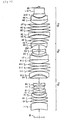
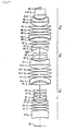
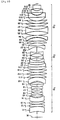
- Figures 2, 5, 8 and 11 show the lens structures for the Embodiments 1 through 4 of the projection optical system of the present invention.
- Common to each of the different lens structure embodiments of the projection optical system of the present invnetion in order from the side of reticle R as the first object is:
- an excimer laser is used as a light source inside the illumination device IS to supply light beams having 193.4 nm of an exposure center wavelength ⁇ .
- First lens group G1 comprises 14 lens elements L11 through L114, which are made of quartz.
- Second lens group G2 comprises 4 lens elements L21 through L24, which are made of quartz.
- Third lens group G3 comprises 11 lens elements L31 through L311; with 6 of the lens elements in group 3 made of fluorite, and the other 5 made of quartz.
- First lens group G1 comprises 14 lens elements L11 through L114, which are made of quartz.
- Second lens group G2 comprises 4 lens elements L21 through L24, which are made of quartz.
- Third lens group G3 comprises 11 lens elements L31 through L311; with only lens elements L31, L33 and L38 made of fluorite and the remaining 8 lens elements made of quartz. Therefore, this embodiment has a higher necessity to satisfy the condition of equation (8).
- NA at the image end is 0.6
- projection magnification ⁇ is 1/4
- diameter of exposure area at the image end is 26.8.
- chromatic aberrations are compensated by consideration of ⁇ 1pm of spectrum range
- First lens group G1 comprises 15 lens elements L11 through L115; with the last 2 lens elements L114 and L115 made of fluorite and the remaining 13 lens elements made of quartz.
- Second lens group G2 comprises 4 lens elements L21 through L24, which are made of quartz.
- Third lens group G3 comprises 10 lens elements L31 through L310; with 5 of the lens elements made of fluorite, and the other 5 lens elements made of quartz.
- This embodiment differs from Embodiments 1 and 2 in the fact that the first lens group G1 comprises fluorite lens elements.
- Embodiments 1 through 3 compensations of both chromatic aberrations and coma aberrations are accomplished by placing biconvex fluorite lens element L33 and meniscus quartz lens element L34 having its concave surface toward the objective end adjacent to each other at a high position of the paraxial ray height in the third lens group G3.
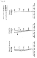
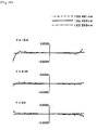
- Figure 3 shows spherical aberrations, astigmatism and distortion of Embodiment 1.
- Figure 4 shows lateral aberrations of Embodiment 1.
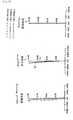
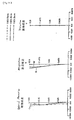
- Figures 6 and 7 show various aberrations of Embodiment 2.
- Figures 9 and 10 show various aberrations for Embodiment 3.
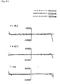
- Figures 12 and 13 show various aberrations for Embodiment 4.
- M indicates a meridional image plane
- S indicates a sagittal image plane.
- Y indicates an image height in each of the figures showing various aberrations.
- each of the embodiments comprise a required lens structure which satisfies conditions (1) through (9) such that fine imaging performance is obtained.
- an excimer laser is used as an exposure light source at 193.4nm in all of the above embodiments it is obvious that the invention is not limited to an excimer laser light source of 193.4nm or to any given excimer laser light source.
- an ultraviolet light source such as an excimer laser supplying 248.4 nm light beamsmay be used or a mercury ark lamp supplying a g-line (436 nm) or an i-line (365 nm) or even other light sources outside the ultraviolet region may be applied.
- First lens group G1 comprises 14 lens elements L11 through L114; with the last 4 lens elements L111 through L114 made of fluorite, and the other 10 lens elements made of quartz.
- Second lens group G2 comprises 7 lens elements L21 through L27; with 2 of the lens elements L22 and L25 made of fluorite, and the remaining 5 lens elements made of quartz.
- the third lens group G3 comprises 15 lens elements L31 through L315; with 10 of the lens elements made of fluorite, and the other 5 lens elements made of quartz.
- chromatic aberrations are compensated by consideration of ⁇ 100pm of spectrum range. Dispersion corresponding to a range of ⁇ 100pm is about 100 times larger than dispersion corresponding to a range of ⁇ 1pm. Therefore, fluorite lens elements are placed in first lens group G1 as well as in second lens group G2. Also, in this embodiment, compensations of both chromatic aberrations and coma aberrations are accomplished by a structure in which:
- Refractive indexes n of quartz (SiO 2 ) and fluorite (CaF 2 ) corresponding to exposure wavelength of 193.4 nm are:
Landscapes
- Physics & Mathematics (AREA)
- General Physics & Mathematics (AREA)
- Optics & Photonics (AREA)
- Lenses (AREA)
- Exposure Of Semiconductors, Excluding Electron Or Ion Beam Exposure (AREA)
- Exposure And Positioning Against Photoresist Photosensitive Materials (AREA)
Applications Claiming Priority (3)
| Application Number | Priority Date | Filing Date | Title |
|---|---|---|---|
| JP10250497 | 1997-04-03 | ||
| JP10250497A JP3823436B2 (ja) | 1997-04-03 | 1997-04-03 | 投影光学系 |
| JP102504/97 | 1997-04-03 |
Publications (3)
| Publication Number | Publication Date |
|---|---|
| EP0869382A2 EP0869382A2 (en) | 1998-10-07 |
| EP0869382A3 EP0869382A3 (en) | 1999-05-06 |
| EP0869382B1 true EP0869382B1 (en) | 2004-06-23 |
Family
ID=14329243
Family Applications (1)
| Application Number | Title | Priority Date | Filing Date |
|---|---|---|---|
| EP98106068A Expired - Lifetime EP0869382B1 (en) | 1997-04-03 | 1998-04-02 | Projection optical system |
Country Status (4)
| Country | Link |
|---|---|
| US (1) | US6088171A (enExample) |
| EP (1) | EP0869382B1 (enExample) |
| JP (1) | JP3823436B2 (enExample) |
| DE (1) | DE69824658T2 (enExample) |
Families Citing this family (22)
| Publication number | Priority date | Publication date | Assignee | Title |
|---|---|---|---|---|
| JP3925576B2 (ja) | 1997-07-24 | 2007-06-06 | 株式会社ニコン | 投影光学系、該光学系を備えた露光装置、及び該装置を用いたデバイスの製造方法 |
| JPH1195095A (ja) | 1997-09-22 | 1999-04-09 | Nikon Corp | 投影光学系 |
| JPH11214293A (ja) | 1998-01-22 | 1999-08-06 | Nikon Corp | 投影光学系及び該光学系を備えた露光装置並びにデバイス製造方法 |
| US6700645B1 (en) | 1998-01-22 | 2004-03-02 | Nikon Corporation | Projection optical system and exposure apparatus and method |
| JP2000143278A (ja) * | 1998-11-10 | 2000-05-23 | Nikon Corp | 耐久性の向上された投影露光装置及び結像光学系の製造方法 |
| DE19942281A1 (de) | 1999-05-14 | 2000-11-16 | Zeiss Carl Fa | Projektionsobjektiv |
| WO2001023933A1 (en) | 1999-09-29 | 2001-04-05 | Nikon Corporation | Projection optical system |
| EP1139138A4 (en) * | 1999-09-29 | 2006-03-08 | Nikon Corp | PROJECTION EXPOSURE PROCESS, DEVICE AND OPTICAL PROJECTION SYSTEM |
| EP1094350A3 (en) | 1999-10-21 | 2001-08-16 | Carl Zeiss | Optical projection lens system |
| JP2004524554A (ja) | 2000-12-22 | 2004-08-12 | カール・ツアイス・エスエムテイ・アーゲー | 投射対物レンズ |
| DE10064685A1 (de) * | 2000-12-22 | 2002-07-04 | Zeiss Carl | Lithographieobjektiv mit einer ersten Linsengruppe, bestehend ausschließlich aus Linsen positiver Brechkraft |
| JP2002244034A (ja) | 2001-02-21 | 2002-08-28 | Nikon Corp | 投影光学系および該投影光学系を備えた露光装置 |
| JP2002323653A (ja) * | 2001-02-23 | 2002-11-08 | Nikon Corp | 投影光学系,投影露光装置および投影露光方法 |
| JP2002323652A (ja) | 2001-02-23 | 2002-11-08 | Nikon Corp | 投影光学系,該投影光学系を備えた投影露光装置および投影露光方法 |
| WO2002103413A1 (en) * | 2001-06-15 | 2002-12-27 | Nikon Corporation | Optical member, process for producing the same, and projection aligner |
| KR100908587B1 (ko) * | 2001-07-17 | 2009-07-22 | 가부시키가이샤 니콘 | 광학 부재의 제조 방법 |
| US7154676B2 (en) | 2002-03-01 | 2006-12-26 | Carl Zeiss Smt A.G. | Very-high aperture projection objective |
| US8208198B2 (en) | 2004-01-14 | 2012-06-26 | Carl Zeiss Smt Gmbh | Catadioptric projection objective |
| US20080151364A1 (en) | 2004-01-14 | 2008-06-26 | Carl Zeiss Smt Ag | Catadioptric projection objective |
| KR20170028451A (ko) | 2004-05-17 | 2017-03-13 | 칼 짜이스 에스엠티 게엠베하 | 중간이미지를 갖는 카타디옵트릭 투사 대물렌즈 |
| CN101438196B (zh) * | 2006-05-05 | 2011-03-02 | 卡尔·蔡司Smt股份公司 | 用于微光刻的具有四个透镜组的对称物镜 |
| US8345350B2 (en) * | 2008-06-20 | 2013-01-01 | Carl Zeiss Smt Gmbh | Chromatically corrected objective with specifically structured and arranged dioptric optical elements and projection exposure apparatus including the same |
Family Cites Families (12)
| Publication number | Priority date | Publication date | Assignee | Title |
|---|---|---|---|---|
| GB2153543B (en) * | 1983-12-28 | 1988-09-01 | Canon Kk | A projection exposure apparatus |
| US4811055A (en) * | 1984-02-27 | 1989-03-07 | Canon Kabushiki Kaisha | Projection exposure apparatus |
| JPH09311278A (ja) * | 1996-05-20 | 1997-12-02 | Nikon Corp | 反射屈折光学系 |
| JP3747951B2 (ja) * | 1994-11-07 | 2006-02-22 | 株式会社ニコン | 反射屈折光学系 |
| US5568325A (en) * | 1993-08-25 | 1996-10-22 | Asahi Kogaku Kogyo Kabushiki Kaisha | Achromatic lens system |
| JPH07128590A (ja) * | 1993-10-29 | 1995-05-19 | Olympus Optical Co Ltd | 縮小投影レンズ |
| JPH0817719A (ja) * | 1994-06-30 | 1996-01-19 | Nikon Corp | 投影露光装置 |
| JPH08179204A (ja) * | 1994-11-10 | 1996-07-12 | Nikon Corp | 投影光学系及び投影露光装置 |
| JPH08203812A (ja) * | 1995-01-30 | 1996-08-09 | Nikon Corp | 反射屈折縮小投影光学系及び露光装置 |
| JPH103041A (ja) * | 1996-06-14 | 1998-01-06 | Nikon Corp | 反射屈折縮小光学系 |
| JPH103040A (ja) * | 1996-06-14 | 1998-01-06 | Nikon Corp | 反射屈折光学系 |
| JPH1020195A (ja) * | 1996-06-28 | 1998-01-23 | Nikon Corp | 反射屈折光学系 |
-
1997
- 1997-04-03 JP JP10250497A patent/JP3823436B2/ja not_active Expired - Fee Related
-
1998
- 1998-04-02 US US09/054,082 patent/US6088171A/en not_active Expired - Lifetime
- 1998-04-02 EP EP98106068A patent/EP0869382B1/en not_active Expired - Lifetime
- 1998-04-02 DE DE69824658T patent/DE69824658T2/de not_active Expired - Lifetime
Also Published As
| Publication number | Publication date |
|---|---|
| DE69824658T2 (de) | 2005-07-07 |
| US6088171A (en) | 2000-07-11 |
| DE69824658D1 (de) | 2004-07-29 |
| EP0869382A2 (en) | 1998-10-07 |
| JP3823436B2 (ja) | 2006-09-20 |
| JPH10282411A (ja) | 1998-10-23 |
| EP0869382A3 (en) | 1999-05-06 |
Similar Documents
| Publication | Publication Date | Title |
|---|---|---|
| EP0869382B1 (en) | Projection optical system | |
| JP3500745B2 (ja) | 投影光学系、投影露光装置及び投影露光方法 | |
| JP3454390B2 (ja) | 投影光学系、投影露光装置及び投影露光方法 | |
| JP3624973B2 (ja) | 投影光学系 | |
| US6157498A (en) | Dual-imaging optical system | |
| US6008884A (en) | Projection lens system and apparatus | |
| JP3396935B2 (ja) | 投影光学系及び投影露光装置 | |
| US5555479A (en) | Reduction projection lens system including refractive and diffractive optical elements | |
| JP3819048B2 (ja) | 投影光学系及びそれを備えた露光装置並びに露光方法 | |
| JP3750123B2 (ja) | 投影光学系 | |
| JP3864399B2 (ja) | 投影露光装置及び該投影露光装置に用いられる投影光学系並びにデバイス製造方法 | |
| US5930049A (en) | Projection optical system and method of using such system for manufacturing devices | |
| KR100573913B1 (ko) | 투영광학계및노광장치 | |
| US6879383B2 (en) | Large-field unit-magnification projection system | |
| EP1061396B1 (en) | Projection optical system and projection exposure apparatus using the same | |
| JPH103039A (ja) | 反射屈折光学系 | |
| JPH07140384A (ja) | 投影光学系及び投影露光装置 | |
| JPH10115779A (ja) | 投影光学系 | |
| JP2008519433A (ja) | アポクロマート等倍投影光学系 | |
| US6862078B2 (en) | Projection optical system and exposure apparatus with the same | |
| JP2000353661A (ja) | 投影光学系および露光装置 | |
| JP2869849B2 (ja) | 集積回路製造方法 | |
| JPH0821955A (ja) | 反射屈折縮小投影光学系 | |
| JP2002169098A (ja) | 結像光学系及び該光学系を備える深紫外光用顕微鏡光学系 | |
| JP2000131607A (ja) | 投影光学系 |
Legal Events
| Date | Code | Title | Description |
|---|---|---|---|
| PUAI | Public reference made under article 153(3) epc to a published international application that has entered the european phase |
Free format text: ORIGINAL CODE: 0009012 |
|
| AK | Designated contracting states |
Kind code of ref document: A2 Designated state(s): DE NL |
|
| PUAL | Search report despatched |
Free format text: ORIGINAL CODE: 0009013 |
|
| AK | Designated contracting states |
Kind code of ref document: A3 Designated state(s): AT BE CH CY DE DK ES FI FR GB GR IE IT LI LU MC NL PT SE |
|
| AX | Request for extension of the european patent |
Free format text: AL;LT;LV;MK;RO;SI |
|
| 17P | Request for examination filed |
Effective date: 19990928 |
|
| AKX | Designation fees paid |
Free format text: DE NL |
|
| GRAP | Despatch of communication of intention to grant a patent |
Free format text: ORIGINAL CODE: EPIDOSNIGR1 |
|
| GRAS | Grant fee paid |
Free format text: ORIGINAL CODE: EPIDOSNIGR3 |
|
| 17Q | First examination report despatched |
Effective date: 20040210 |
|
| GRAA | (expected) grant |
Free format text: ORIGINAL CODE: 0009210 |
|
| AK | Designated contracting states |
Kind code of ref document: B1 Designated state(s): DE NL |
|
| REF | Corresponds to: |
Ref document number: 69824658 Country of ref document: DE Date of ref document: 20040729 Kind code of ref document: P |
|
| PLBE | No opposition filed within time limit |
Free format text: ORIGINAL CODE: 0009261 |
|
| STAA | Information on the status of an ep patent application or granted ep patent |
Free format text: STATUS: NO OPPOSITION FILED WITHIN TIME LIMIT |
|
| 26N | No opposition filed |
Effective date: 20050324 |
|
| PGFP | Annual fee paid to national office [announced via postgrant information from national office to epo] |
Ref country code: DE Payment date: 20120419 Year of fee payment: 15 Ref country code: NL Payment date: 20120425 Year of fee payment: 15 |
|
| REG | Reference to a national code |
Ref country code: NL Ref legal event code: V1 Effective date: 20131101 |
|
| PG25 | Lapsed in a contracting state [announced via postgrant information from national office to epo] |
Ref country code: DE Free format text: LAPSE BECAUSE OF NON-PAYMENT OF DUE FEES Effective date: 20131101 |
|
| REG | Reference to a national code |
Ref country code: DE Ref legal event code: R119 Ref document number: 69824658 Country of ref document: DE Effective date: 20131101 |
|
| PG25 | Lapsed in a contracting state [announced via postgrant information from national office to epo] |
Ref country code: NL Free format text: LAPSE BECAUSE OF NON-PAYMENT OF DUE FEES Effective date: 20131101 |