EP0868938B1 - Verfahren zur NO-Entfernung aus motorischen Abgasen - Google Patents
Verfahren zur NO-Entfernung aus motorischen Abgasen Download PDFInfo
- Publication number
- EP0868938B1 EP0868938B1 EP98102576A EP98102576A EP0868938B1 EP 0868938 B1 EP0868938 B1 EP 0868938B1 EP 98102576 A EP98102576 A EP 98102576A EP 98102576 A EP98102576 A EP 98102576A EP 0868938 B1 EP0868938 B1 EP 0868938B1
- Authority
- EP
- European Patent Office
- Prior art keywords
- cathode side
- solid electrolyte
- present
- exhaust gas
- electrode
- Prior art date
- Legal status (The legal status is an assumption and is not a legal conclusion. Google has not performed a legal analysis and makes no representation as to the accuracy of the status listed.)
- Expired - Lifetime
Links
Images





Classifications
-
- B—PERFORMING OPERATIONS; TRANSPORTING
- B01—PHYSICAL OR CHEMICAL PROCESSES OR APPARATUS IN GENERAL
- B01D—SEPARATION
- B01D53/00—Separation of gases or vapours; Recovering vapours of volatile solvents from gases; Chemical or biological purification of waste gases, e.g. engine exhaust gases, smoke, fumes, flue gases, aerosols
- B01D53/32—Separation of gases or vapours; Recovering vapours of volatile solvents from gases; Chemical or biological purification of waste gases, e.g. engine exhaust gases, smoke, fumes, flue gases, aerosols by electrical effects other than those provided for in group B01D61/00
- B01D53/326—Separation of gases or vapours; Recovering vapours of volatile solvents from gases; Chemical or biological purification of waste gases, e.g. engine exhaust gases, smoke, fumes, flue gases, aerosols by electrical effects other than those provided for in group B01D61/00 in electrochemical cells
-
- F—MECHANICAL ENGINEERING; LIGHTING; HEATING; WEAPONS; BLASTING
- F01—MACHINES OR ENGINES IN GENERAL; ENGINE PLANTS IN GENERAL; STEAM ENGINES
- F01N—GAS-FLOW SILENCERS OR EXHAUST APPARATUS FOR MACHINES OR ENGINES IN GENERAL; GAS-FLOW SILENCERS OR EXHAUST APPARATUS FOR INTERNAL-COMBUSTION ENGINES
- F01N3/00—Exhaust or silencing apparatus having means for purifying, rendering innocuous, or otherwise treating exhaust
- F01N3/08—Exhaust or silencing apparatus having means for purifying, rendering innocuous, or otherwise treating exhaust for rendering innocuous
- F01N3/0892—Electric or magnetic treatment, e.g. dissociation of noxious components
-
- F—MECHANICAL ENGINEERING; LIGHTING; HEATING; WEAPONS; BLASTING
- F01—MACHINES OR ENGINES IN GENERAL; ENGINE PLANTS IN GENERAL; STEAM ENGINES
- F01N—GAS-FLOW SILENCERS OR EXHAUST APPARATUS FOR MACHINES OR ENGINES IN GENERAL; GAS-FLOW SILENCERS OR EXHAUST APPARATUS FOR INTERNAL-COMBUSTION ENGINES
- F01N3/00—Exhaust or silencing apparatus having means for purifying, rendering innocuous, or otherwise treating exhaust
- F01N3/08—Exhaust or silencing apparatus having means for purifying, rendering innocuous, or otherwise treating exhaust for rendering innocuous
- F01N3/10—Exhaust or silencing apparatus having means for purifying, rendering innocuous, or otherwise treating exhaust for rendering innocuous by thermal or catalytic conversion of noxious components of exhaust
- F01N3/18—Exhaust or silencing apparatus having means for purifying, rendering innocuous, or otherwise treating exhaust for rendering innocuous by thermal or catalytic conversion of noxious components of exhaust characterised by methods of operation; Control
- F01N3/20—Exhaust or silencing apparatus having means for purifying, rendering innocuous, or otherwise treating exhaust for rendering innocuous by thermal or catalytic conversion of noxious components of exhaust characterised by methods of operation; Control specially adapted for catalytic conversion
-
- B—PERFORMING OPERATIONS; TRANSPORTING
- B01—PHYSICAL OR CHEMICAL PROCESSES OR APPARATUS IN GENERAL
- B01D—SEPARATION
- B01D2257/00—Components to be removed
- B01D2257/40—Nitrogen compounds
- B01D2257/404—Nitrogen oxides other than dinitrogen oxide
-
- Y—GENERAL TAGGING OF NEW TECHNOLOGICAL DEVELOPMENTS; GENERAL TAGGING OF CROSS-SECTIONAL TECHNOLOGIES SPANNING OVER SEVERAL SECTIONS OF THE IPC; TECHNICAL SUBJECTS COVERED BY FORMER USPC CROSS-REFERENCE ART COLLECTIONS [XRACs] AND DIGESTS
- Y02—TECHNOLOGIES OR APPLICATIONS FOR MITIGATION OR ADAPTATION AGAINST CLIMATE CHANGE
- Y02T—CLIMATE CHANGE MITIGATION TECHNOLOGIES RELATED TO TRANSPORTATION
- Y02T10/00—Road transport of goods or passengers
- Y02T10/10—Internal combustion engine [ICE] based vehicles
- Y02T10/12—Improving ICE efficiencies
Definitions
- the invention relates to a method for removing NO from the exhaust gas of Internal combustion engines, in particular for use in a motor vehicle.
- the document US 5,409,591 describes a method for sensory determination the NO content in exhaust gases of an internal combustion engine. In this method, NO taken to generate a detector signal from the exhaust gas and a solid electrolyte transported.
- the document DE 195 27 693 discloses a method for NO reduction in exhaust gases of internal combustion engines in which NO is catalytically reduced to N 2 and O 2- on a cathode, and the O 2- ions are subsequently passed through an O 2 -conductive Solid state electrolytes are forwarded to an anode. There they are unloaded and released as O 2 molecules.
- the publications DE 36 44 090 and EP 0,566,071 disclose a method for the reduction of NO x - containing exhaust gases from internal combustion engines by the NO x is catalytically reduced with N 2 .
- the hydrogen is formed by electrolysis by means of a solid electrolyte or an H + -conducting membrane from the water vapor contained in the exhaust gas.
- the invention is based on the object, a method for NO removal from motor To provide exhaust gases with which existing in the known methods Disadvantages, in particular with regard to activity, selectivity and Long-term resistance to be overcome.
- a NO + electrochemical solid electrolyte which is arranged between two electrodes is used which, when an electrical voltage is applied, extracts NO from the exhaust gas and transports it to an enrichment cell. NO is oxidized anodically to NO + on the exhaust gas side and transported as such through the solid electrolyte. At the cathode, the nitrogen oxide cations are then reduced to NO.
- the solid electrolyte is generally a cation-conducting solid.
- An exemplary embodiment is called NO + or Ag + -exchanged beta-alumina.
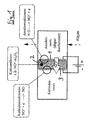
- Fig. 1 shows the principle of operation of the method according to the invention. It can be seen the two electrodes (anode 1, cathode 3), between which by means of an external voltage source a certain voltage difference is maintained, as well as the cation-conducting solid electrolyte 2 between the two electrodes 1.3.
- solid electrolyte 2 for example, a NO + -exchanged beta-alumina is used.
- the exhaust gas of the internal combustion engine flows through the anode compartment.
- the NO becomes according to the reaction NO ---> NO + + + e - oxidized to NO + .
- the NO + ions are transported through the solid electrolyte 2 and at the cathode 3 according to the reaction NO + + e - ---> NO reduced to NO. How to proceed with the so enriched on the cathode side nitrogen oxides (process variants A to E), is shown in Figs. 2 to 6 in detail.
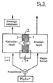
- Fig. 2 shows a first process variant (case A), in which the at the cathode side present NO is returned via the intake air in the engine combustion chamber becomes.
- the engine combustion chamber is then analogous to the above SNR method the reduction of NO during combustion.
- This process has the following advantages: At the moment in development SNR method is so far no NO-storing material with sufficiently high long-term stability in the exhaust known.
- the method described can completely replace NO enrichment with NO adsorbent.
- Another advantage is the continuous operation of the process. That up NO adsorption based SNR processes must be due to the adsorption and Desorption phase can be operated cyclically.
- Fig. 3 shows case B in which the NO present on the cathode side is reacted under stoichiometric or rich exhaust conditions in lean burn gasoline engines (direct injection or port injection).
- the exhaust gas flow is controlled by an exhaust flap.
- the engine exhaust gases are directed into the anode compartment, where the NO is oxidized to NO + in accordance with the present invention.
- the exhaust gas is passed through the NO enriched cathode compartment and further to a known three-way catalyst.
- NO X storage catalysts are currently being developed for use in lean burn gasoline engines. Due to the low resistance to SO X and high temperatures, the NO X -storing material (nitrate storage) presents a particular problem. The described process makes it possible to completely dispense with this component.
- FIG. 4 shows an embodiment in which the NO present on the cathode side is reacted on a catalyst using a reducing agent (case C).
- a gaseous reducing agent for example hydrocarbons, CO, H 2 .
- the catalyst in particular, a three-way catalyst or a NO cracking catalyst can be used.
- the catalyst can be arranged on the cathode 3 or downstream of the cathode space.
- the reducing agent can be generated on board the motor vehicle or carried in a tank.
- the reduction of NO on the cathode side with the gaseous reducing agent can be carried out highly selectively by the absence of oxygen become. As a result, higher NO conversions are at the same time reduced Achieved reductant requirement.
- Fig. 5 shows case D as a further embodiment of the invention in which the NO present on the cathode side is converted by catalytic reduction with H 2 .
- the solid electrolyte 2 for example beta-Al 2 O 3, can also transport H + ions in addition to the NO + ions.
- the cathode 3 is coated with a known DENOX catalyst.
- H + ions also pass through the solid electrolyte 2 in addition to the NO + ions.
- the H + ions are derived from the water present in the engine exhaust after the reaction: 2 H 2 O ---> O 2 + 4H + + + 4e - .
- the H + ions become at the cathode according to the reaction 2H + + 2e - ---> H 2 reduced to N 2 .
- the reaction takes place NO + H 2 ---> N 2 + H 2 O.
- the reduction of NO with hydrogen generated simultaneously at the cathode can be carried out highly selectively by the absence of oxygen.
- FIG. 6 shows an embodiment (case E) in which the NO present on the cathode side is catalytically reduced to N 2 and O 2 , the O 2- ions subsequently being passed on through an O 2 -type solid electrolyte 4.
- the structure is as follows: As in the previous embodiments, anode 1, NO + ion-conducting solid electrolyte 2, eg NO + -exchanged Al 2 O 3 and cathode 3 are present.
- the cathode 3 is coated with a NO gap catalyst, on which the cathode-side NO after the reaction 2 NO ---> N 2 + 2 O (ad) O (ad) + 2e - ---> O 2- is split.
- anodically connected electrode 5 is present, wherein there is a voltage difference between this further electrode 5 and the cathode 3.
- an O 2- conductive solid electrolyte 4, zirconia, for example is arranged between the electrode 3 and the further electrode 5.
- the resulting at the cathode 3 oxygen O 2- gap is transported by the O 2 -conducting solid electrolyte 4 through to the other electrode 5, discharged there and discharged as O 2 molecules: O 2- ---> O (ad) + 2e - 2 O (ad) ---> O 2 (g) with (g): gaseous.
- the use of a reducing agent completely dispensed with The used electrical energy is used selectively only to transport NO through the electrolyte.
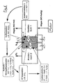
- Fig. 7 shows an experimental setup for carrying out the method according to the invention.
- a current flows, which increases with the voltage.
- the current goes back despite a constant voltage.
- the current flow is clearly due to the implementation of NO.
- Fig. 8 shows the corresponding time courses of voltage and current.
Landscapes
- Chemical & Material Sciences (AREA)
- Engineering & Computer Science (AREA)
- Chemical Kinetics & Catalysis (AREA)
- Mechanical Engineering (AREA)
- Toxicology (AREA)
- Combustion & Propulsion (AREA)
- Health & Medical Sciences (AREA)
- General Engineering & Computer Science (AREA)
- Electrochemistry (AREA)
- Analytical Chemistry (AREA)
- General Chemical & Material Sciences (AREA)
- Oil, Petroleum & Natural Gas (AREA)
- Exhaust Gas After Treatment (AREA)
- Treating Waste Gases (AREA)
Description
- DENOX-KatalyseDie Stickoxide werden unter Einsatz eines Reduktionsmittels, Ammoniak oder ein Kohlenwasserstoff, an einem geeigneten Katalysator zu Stickstoff und Wasser und bei Einsatz eines Kohlenwasserstoffs zusätzlich zu Kohlendioxid umgesetzt.Bislang entwickelte DENOX-Katalysatoren verfügen über eine noch zu geringe Aktivität und Selektivität. Weiterhin ist größtenteils die Langzeitstabilität im Abgas begrenzt.
- NOX-Speicher-KatalysatorenDer Katalysator besteht aus zwei Komponenten, einem NOX-speichernden Material und einem Dreiwegekatalysator. Die Stickoxide werden im Magerbetrieb des Motors in der Speicherkomponente als Nitrat chemisch gebunden und in einer Regenerationsphase unter stöchiometrisch oder fetten Motorbetriebsphasen freigesetzt und am Dreiwegekatalysator zu Stickstoff umgesetzt.Die noch zu geringe Resistenz des NOX-speichernden Materials gegen SOX sowie dessen begrenzte thermische Stabilität verhindern derzeit den Serieneinsatz dieses Katalysatortyps.
- SNR-Verfahren (selektive NOX-Rückführung)Die Stickoxide werden an einem geeigneten Material im Abgas gespeichert und nach vollständiger Beladung des NOX-Speichers über eine entsprechende Klappenschaltung in der Abgasführung über die Ansaugluft in den Motorbrennraum rückgeführt, wo die Reduktion des NO bei der Verbrennung stattfindet.Eine noch unzureichende Beladungskapazität des NOX-Speichers, sowie dessen begrenzte Lebensdauer im Abgas verhindern bislang den Serieneinsatz des SNR-Verfahrens.
- Fall ARückführung des NO über die Ansaugluft in den Motorbrennraum (nach SNR-Prinzip) (Fig. 2).
- Fall BUmsetzung des NO unter stöchiometrisch/fetten Abgasbedingungen bei magermixbetriebenen Ottomotoren (Direkteinspritzung oder Saugrohreinspritzung) (Fig. 3).
- Fall CUmsetzung des NO mit gasförmigen Reduktionsmitteln (z.B Kohlenwasserstoff, CO, H2), der an Bord des Kraftfahrzeugs erzeugt oder mitgeführt wird (Fig. 4).
- Fall Dkatalytische Reduktion des NO mit H2, der als H+ (aus abgasseitigem Wasser) ebenfalls durch den Festelektrolyt oder durch eine zusätzliche H+-leitende Membran (z.B. PEM Proton Exchange Membran) transportiert wird (Fig. 5).
- Fall ESpaltung des NO auf der Kathodenseite an geeignetem Katalysator unter Freisetzung des N2 (gasförmig) und Weiterleitung des Spaltsauerstoffs mittels eines an sich bekannten O2--Ionenleiters (Fig. 6).
- Fig. 1
- eine Prinzipskizze zum Ablauf des erfindungsgemäßen Verfahrens;
- Fig. 2 bis 6
- Verfahrensvarianten entsprechend der erwähnten Fälle A bis E,
- Fig. 7
- einen Versuchsaufbau zur Durchführung des erfindungsgemäßen Verfahrens,
- Fig. 8
- den Verlauf von Spannung U (links, in Volt) und Stromstärke I (rechts, in mA) über der Zeit (in Minuten), gemessen an einem Versuchsaufbau nach Fig. 7.
Claims (7)
- Verfahren zur Entfernung von NO aus dem Abgas von Verbrennungsmotoren, wobei das NO-haltige Abgas an eine erste Elektrode (1) geleitet wird, an der das NO anodisch zu NO+ oxidiert wird, das NO+ anschließend durch einen NO+ - leitenden Festelektrolyten (2), der sich an die erste Elektrode (1) anschließt, zu einer zweiten Elektrode (3) transportiert wird, an der das NO kathodisch reduziert wird, dadurch gekennzeichnet, daß das NO auf der Kathodenseite katalytisch untere Bildung von N2 umgesetzt oder in den Motorbrennraum rückgeführt wird.
- Verfahren nach Anspruch 1, dadurch gekennzeichnet, daß das auf der Kathodenseite vorliegende NO über die Ansaugluft in den Motorbrennraum geführt und dort umgesetzt wird.
- Verfahren nach Anspruch 1, dadurch gekennzeichnet, daß das auf der Kathodenseite vorliegende NO unter stöchiometrischen oder fetten Abgasbedingungen an einem Dreiwegekatalysator umgesetzt wird.
- Verfahren nach Anspruch 1, dadurch gekennzeichnet, daß das auf der Kathodenseite vorliegende NO mittels eines gasförmigem Reduktionsmittels katalytisch umgesetzt wird.
- Verfahren nach Anspruch 1, dadurch gekennzeichnet, daß das auf der Kathodenseite vorliegende NO mit H2 katalytisch reduziert wird, wobei der benötigte Wasserstoff aus dem abgasseitigem Wasser stammt, und durch den Festelektrolyten (2) oder durch eine zusätzliche H+-leitende Membran auf die Kathodenseite transportiert wird.
- Verfahren nach Anspruch 1, dadurch gekennzeichnet, daß das auf der Kathodenseite vorliegende NO katalytisch zu N2 und O2- reduziert wird, wobei die O2--Ionen anschließend durch einen O2--Ieitenden Festelektrolyten (4), der sich an die zweite Elektrode (3) anschließt, weitergeleitet werden.
- Verfahren nach einem der vorangehenden Ansprüche, dadurch gekennzeichnet, daß der Festelektrolyt ein mit Ag+- oder NO+-ausgetauschtes beta-Aluminiumoxid ist.
Applications Claiming Priority (2)
| Application Number | Priority Date | Filing Date | Title |
|---|---|---|---|
| DE19713633A DE19713633C1 (de) | 1997-04-02 | 1997-04-02 | Verfahren zur NO-Entfernung aus motorischen Abgasen |
| DE19713633 | 1997-04-02 |
Publications (3)
| Publication Number | Publication Date |
|---|---|
| EP0868938A2 EP0868938A2 (de) | 1998-10-07 |
| EP0868938A3 EP0868938A3 (de) | 1999-03-24 |
| EP0868938B1 true EP0868938B1 (de) | 2003-07-23 |
Family
ID=7825256
Family Applications (1)
| Application Number | Title | Priority Date | Filing Date |
|---|---|---|---|
| EP98102576A Expired - Lifetime EP0868938B1 (de) | 1997-04-02 | 1998-02-14 | Verfahren zur NO-Entfernung aus motorischen Abgasen |
Country Status (4)
| Country | Link |
|---|---|
| US (1) | US6015483A (de) |
| EP (1) | EP0868938B1 (de) |
| DE (2) | DE19713633C1 (de) |
| ES (1) | ES2203837T3 (de) |
Families Citing this family (11)
| Publication number | Priority date | Publication date | Assignee | Title |
|---|---|---|---|---|
| DE19837505C1 (de) * | 1998-08-19 | 1999-12-30 | Dornier Gmbh | Nitrosyl-Ionen leitender Werkstoff aus NO+-beta"-Al¶2¶O¶3¶ und Verfahren zu seiner Herstellung |
| DE19847034C2 (de) * | 1998-10-13 | 2000-12-07 | Dornier Gmbh | Verfahren zur Herstellung einer lithiumstabilisierten Me-ß"Al¶2¶O¶3¶-Keramik und deren Verwendung |
| SE523342C2 (sv) | 2000-05-02 | 2004-04-13 | Volvo Teknisk Utveckling Ab | Anordning och förfarande för reduktion av en gaskomponent i en avgasström från en förbränningsmotor |
| JP4217457B2 (ja) * | 2002-10-23 | 2009-02-04 | 三菱電機株式会社 | 窒素酸化物分解素子およびこれを備えた窒素酸化物分解装置 |
| JP2007292010A (ja) * | 2006-04-27 | 2007-11-08 | Toyota Motor Corp | 内燃機関から排気される窒素酸化物を含む排気ガスの浄化 |
| US20110179778A1 (en) * | 2010-01-27 | 2011-07-28 | Gm Global Technology Operations, Inc. | Method and apparatus for exhaust gas aftertreatment from an internal combustion engine |
| TWI390104B (zh) * | 2010-03-04 | 2013-03-21 | Nat Univ Tsing Hua | 控制廢氣排放並發電的熱活電化學暨觸媒轉化器 |
| US8911699B2 (en) * | 2012-08-14 | 2014-12-16 | Clearsign Combustion Corporation | Charge-induced selective reduction of nitrogen |
| KR102566436B1 (ko) * | 2015-08-18 | 2023-08-18 | 한국과학기술원 | 철-에틸렌디아민사아세트산을 이용한 질소화합물 포집용 전기분해장치 |
| JP6881279B2 (ja) * | 2017-12-26 | 2021-06-02 | トヨタ自動車株式会社 | 電気化学リアクタ及び電気化学リアクタを備えた内燃機関 |
| CN114032557B (zh) * | 2021-11-08 | 2023-03-31 | 郑州大学 | 一种用于去除氮氧化物的固体电解质电池及其制备方法 |
Family Cites Families (9)
| Publication number | Priority date | Publication date | Assignee | Title |
|---|---|---|---|---|
| US3676220A (en) * | 1969-02-27 | 1972-07-11 | Gen Electric | Facilitated transport liquid membrane |
| US3950944A (en) * | 1973-11-14 | 1976-04-20 | Toyo Kogyo Co., Ltd. | Exhaust gas cleaning system for the internal combustion engine |
| DE3644090A1 (de) * | 1986-12-23 | 1988-07-07 | Bbc Brown Boveri & Cie | Verfahren und vorrichtung zum reinigen von abgasen |
| US4738760A (en) * | 1987-09-01 | 1988-04-19 | Institute Of Gas Technology | Electrochemical separation of oxygen |
| US5352337A (en) * | 1992-04-14 | 1994-10-04 | Kabushiki Kaisha Toyota Chuo Kenkyusho | Method for reducing nitrogen oxides |
| US5401372A (en) * | 1993-04-26 | 1995-03-28 | Ceramatec, Inc. | Electrochemical catalytic reduction cell for the reduction of NOx in an O2 -containing exhaust emission |
| US5409591A (en) * | 1993-09-24 | 1995-04-25 | Baker; Charles K. | Selective electrochemical detector for nitric oxide and method |
| DE19547921C2 (de) * | 1995-01-13 | 1998-09-24 | Dornier Gmbh | Verfahren und Vorrichtung zur katalytischen NO-Reduzierung von Kfz-Abgasen |
| DE19527693C1 (de) * | 1995-07-28 | 1996-10-10 | Dornier Gmbh | Verfahren zur Stickstoffmonoxid-Minderung in Abgasen von Verbrennungsmaschinen |
-
1997
- 1997-04-02 DE DE19713633A patent/DE19713633C1/de not_active Expired - Fee Related
-
1998
- 1998-02-14 DE DE59809044T patent/DE59809044D1/de not_active Expired - Fee Related
- 1998-02-14 ES ES98102576T patent/ES2203837T3/es not_active Expired - Lifetime
- 1998-02-14 EP EP98102576A patent/EP0868938B1/de not_active Expired - Lifetime
- 1998-04-02 US US09/053,517 patent/US6015483A/en not_active Expired - Fee Related
Also Published As
| Publication number | Publication date |
|---|---|
| DE59809044D1 (de) | 2003-08-28 |
| EP0868938A3 (de) | 1999-03-24 |
| EP0868938A2 (de) | 1998-10-07 |
| DE19713633C1 (de) | 1999-01-28 |
| US6015483A (en) | 2000-01-18 |
| ES2203837T3 (es) | 2004-04-16 |
Similar Documents
| Publication | Publication Date | Title |
|---|---|---|
| EP1395351B1 (de) | Abgasreinigungsanlage mit reduktionsmittelversorgung | |
| DE10021693C2 (de) | Verfahren und Vorrichtung zur Abgasreinigung | |
| DE69204479T2 (de) | Abgasreinigungssystem für eine Brennkraftmaschine. | |
| DE60207767T2 (de) | Methode und Apparat zur Gasreinigung in Energieumwandlungssystemen | |
| US5422085A (en) | Catalytic conversion of internal combustion engine exhaust gases | |
| DE112007000948T5 (de) | Abgasreinigungssystem und Verfahren zum Reinigen von Abgasen | |
| DE19713633C1 (de) | Verfahren zur NO-Entfernung aus motorischen Abgasen | |
| DE102004029235A1 (de) | Vorrichtung und Verfahren zum Betreiben eines Kraftstoffreformers zur Regenerierung einer DPNR-Vorrichtung | |
| US5456807A (en) | Method and apparatus for treating nitrogen oxide-containing gas streams using a combined electrochemical-sorbent approach | |
| EP0988104A1 (de) | Verfahren und vorrichtung zur vernichtung von oxidischen schadstoffen in einem sauerstoffhaltigen abgas sowie damit betriebener motor | |
| DE19635008A1 (de) | Brennstoffbatteriesystem | |
| DE4446280C2 (de) | Verfahren und eine Katalysatoreinheit zur Reduktion von Schadstoffen, insbesondere zur Reduktion von Stickoxiden in Abgasen von Verbrennungskraftmaschinen | |
| DE112006000255T5 (de) | Chemische Reaktionsvorrichtung aus Keramik, die in der Lage ist, festen Kohlenstoff zu zersetzen | |
| DE19651492B4 (de) | Vorrichtung zur NOx-Entfernung aus dem Abgas von Verbrennungsmotoren | |
| EP1279432B1 (de) | Chemischer Reaktor | |
| US6331232B1 (en) | Device and method for reduction of oxides of nitrogen | |
| DE19753573A1 (de) | Abgasreinigungsanlage | |
| DE102010028146A1 (de) | Elektrochemischer NH3-SCR-Reaktor | |
| JP3780763B2 (ja) | 排ガス浄化用電気化学触媒 | |
| JP3757089B2 (ja) | 排ガス浄化触媒のイオウ被毒の再生方法 | |
| DE102008047722A1 (de) | Verfahren zum Betreiben einer Abgasreinigungsanlage | |
| DE102006062051A1 (de) | Sensorelement mit zusätzlicher Diagnosefunktion | |
| WO2004108256A1 (de) | Abgasnachbehandlungsvorrichtung einer brennkraftmaschine | |
| DE102004024370A1 (de) | Verbrennungsmotor mit Hilfsenergieeinheit | |
| DE19816323C1 (de) | Verfahren zur katalytischen Reduktion von Stickoxiden unter Zugabe von Reduktionsmitteln in motorischen Abgasen |
Legal Events
| Date | Code | Title | Description |
|---|---|---|---|
| PUAI | Public reference made under article 153(3) epc to a published international application that has entered the european phase |
Free format text: ORIGINAL CODE: 0009012 |
|
| AK | Designated contracting states |
Kind code of ref document: A2 Designated state(s): DE ES FR GB IT SE |
|
| PUAL | Search report despatched |
Free format text: ORIGINAL CODE: 0009013 |
|
| AK | Designated contracting states |
Kind code of ref document: A3 Designated state(s): AT BE CH DE DK ES FI FR GB GR IE IT LI LU MC NL PT SE |
|
| AX | Request for extension of the european patent |
Free format text: AL;LT;LV;MK;RO;SI |
|
| 17P | Request for examination filed |
Effective date: 19990624 |
|
| AKX | Designation fees paid |
Free format text: DE ES FR GB IT SE |
|
| 17Q | First examination report despatched |
Effective date: 20011008 |
|
| RAP1 | Party data changed (applicant data changed or rights of an application transferred) |
Owner name: DAIMLERCHRYSLER AG |
|
| GRAH | Despatch of communication of intention to grant a patent |
Free format text: ORIGINAL CODE: EPIDOS IGRA |
|
| GRAH | Despatch of communication of intention to grant a patent |
Free format text: ORIGINAL CODE: EPIDOS IGRA |
|
| RBV | Designated contracting states (corrected) |
Designated state(s): DE ES FR GB IT SE |
|
| GRAA | (expected) grant |
Free format text: ORIGINAL CODE: 0009210 |
|
| AK | Designated contracting states |
Designated state(s): DE ES FR GB IT SE |
|
| REG | Reference to a national code |
Ref country code: GB Ref legal event code: FG4D Free format text: NOT ENGLISH |
|
| REF | Corresponds to: |
Ref document number: 59809044 Country of ref document: DE Date of ref document: 20030828 Kind code of ref document: P |
|
| REG | Reference to a national code |
Ref country code: SE Ref legal event code: TRGR |
|
| GBT | Gb: translation of ep patent filed (gb section 77(6)(a)/1977) |
Effective date: 20031017 |
|
| PG25 | Lapsed in a contracting state [announced via postgrant information from national office to epo] |
Ref country code: GB Free format text: LAPSE BECAUSE OF NON-PAYMENT OF DUE FEES Effective date: 20040214 |
|
| PG25 | Lapsed in a contracting state [announced via postgrant information from national office to epo] |
Ref country code: SE Free format text: LAPSE BECAUSE OF NON-PAYMENT OF DUE FEES Effective date: 20040215 |
|
| PG25 | Lapsed in a contracting state [announced via postgrant information from national office to epo] |
Ref country code: ES Free format text: LAPSE BECAUSE OF NON-PAYMENT OF DUE FEES Effective date: 20040216 |
|
| ET | Fr: translation filed | ||
| REG | Reference to a national code |
Ref country code: ES Ref legal event code: FG2A Ref document number: 2203837 Country of ref document: ES Kind code of ref document: T3 |
|
| PLBE | No opposition filed within time limit |
Free format text: ORIGINAL CODE: 0009261 |
|
| STAA | Information on the status of an ep patent application or granted ep patent |
Free format text: STATUS: NO OPPOSITION FILED WITHIN TIME LIMIT |
|
| 26N | No opposition filed |
Effective date: 20040426 |
|
| PG25 | Lapsed in a contracting state [announced via postgrant information from national office to epo] |
Ref country code: DE Free format text: LAPSE BECAUSE OF NON-PAYMENT OF DUE FEES Effective date: 20040901 |
|
| EUG | Se: european patent has lapsed | ||
| GBPC | Gb: european patent ceased through non-payment of renewal fee |
Effective date: 20040214 |
|
| PG25 | Lapsed in a contracting state [announced via postgrant information from national office to epo] |
Ref country code: FR Free format text: LAPSE BECAUSE OF NON-PAYMENT OF DUE FEES Effective date: 20041029 |
|
| REG | Reference to a national code |
Ref country code: FR Ref legal event code: ST |
|
| PG25 | Lapsed in a contracting state [announced via postgrant information from national office to epo] |
Ref country code: IT Free format text: LAPSE BECAUSE OF NON-PAYMENT OF DUE FEES Effective date: 20050214 |
|
| REG | Reference to a national code |
Ref country code: ES Ref legal event code: FD2A Effective date: 20040216 |