EP0866398B1 - Data transmission control in accord with line capacity - Google Patents
Data transmission control in accord with line capacity Download PDFInfo
- Publication number
- EP0866398B1 EP0866398B1 EP98105166A EP98105166A EP0866398B1 EP 0866398 B1 EP0866398 B1 EP 0866398B1 EP 98105166 A EP98105166 A EP 98105166A EP 98105166 A EP98105166 A EP 98105166A EP 0866398 B1 EP0866398 B1 EP 0866398B1
- Authority
- EP
- European Patent Office
- Prior art keywords
- data
- printer
- transmission
- rasterization
- Prior art date
- Legal status (The legal status is an assumption and is not a legal conclusion. Google has not performed a legal analysis and makes no representation as to the accuracy of the status listed.)
- Expired - Lifetime
Links
Images


Classifications
-
- H—ELECTRICITY
- H04—ELECTRIC COMMUNICATION TECHNIQUE
- H04L—TRANSMISSION OF DIGITAL INFORMATION, e.g. TELEGRAPHIC COMMUNICATION
- H04L12/00—Data switching networks
- H04L12/28—Data switching networks characterised by path configuration, e.g. LAN [Local Area Networks] or WAN [Wide Area Networks]
- H04L12/40—Bus networks
- H04L12/40052—High-speed IEEE 1394 serial bus
- H04L12/40058—Isochronous transmission
-
- G—PHYSICS
- G06—COMPUTING OR CALCULATING; COUNTING
- G06F—ELECTRIC DIGITAL DATA PROCESSING
- G06F3/00—Input arrangements for transferring data to be processed into a form capable of being handled by the computer; Output arrangements for transferring data from processing unit to output unit, e.g. interface arrangements
- G06F3/12—Digital output to print unit, e.g. line printer, chain printer
- G06F3/1201—Dedicated interfaces to print systems
- G06F3/1202—Dedicated interfaces to print systems specifically adapted to achieve a particular effect
- G06F3/1211—Improving printing performance
- G06F3/1215—Improving printing performance achieving increased printing speed, i.e. reducing the time between printing start and printing end
-
- G—PHYSICS
- G06—COMPUTING OR CALCULATING; COUNTING
- G06F—ELECTRIC DIGITAL DATA PROCESSING
- G06F3/00—Input arrangements for transferring data to be processed into a form capable of being handled by the computer; Output arrangements for transferring data from processing unit to output unit, e.g. interface arrangements
- G06F3/12—Digital output to print unit, e.g. line printer, chain printer
- G06F3/1201—Dedicated interfaces to print systems
- G06F3/1223—Dedicated interfaces to print systems specifically adapted to use a particular technique
- G06F3/1237—Print job management
- G06F3/1244—Job translation or job parsing, e.g. page banding
- G06F3/1247—Job translation or job parsing, e.g. page banding by conversion to printer ready format
-
- G—PHYSICS
- G06—COMPUTING OR CALCULATING; COUNTING
- G06F—ELECTRIC DIGITAL DATA PROCESSING
- G06F3/00—Input arrangements for transferring data to be processed into a form capable of being handled by the computer; Output arrangements for transferring data from processing unit to output unit, e.g. interface arrangements
- G06F3/12—Digital output to print unit, e.g. line printer, chain printer
- G06F3/1201—Dedicated interfaces to print systems
- G06F3/1278—Dedicated interfaces to print systems specifically adapted to adopt a particular infrastructure
- G06F3/1284—Local printer device
-
- G—PHYSICS
- G06—COMPUTING OR CALCULATING; COUNTING
- G06F—ELECTRIC DIGITAL DATA PROCESSING
- G06F3/00—Input arrangements for transferring data to be processed into a form capable of being handled by the computer; Output arrangements for transferring data from processing unit to output unit, e.g. interface arrangements
- G06F3/12—Digital output to print unit, e.g. line printer, chain printer
- G06F3/1293—Printer information exchange with computer
-
- G—PHYSICS
- G06—COMPUTING OR CALCULATING; COUNTING
- G06Q—INFORMATION AND COMMUNICATION TECHNOLOGY [ICT] SPECIALLY ADAPTED FOR ADMINISTRATIVE, COMMERCIAL, FINANCIAL, MANAGERIAL OR SUPERVISORY PURPOSES; SYSTEMS OR METHODS SPECIALLY ADAPTED FOR ADMINISTRATIVE, COMMERCIAL, FINANCIAL, MANAGERIAL OR SUPERVISORY PURPOSES, NOT OTHERWISE PROVIDED FOR
- G06Q20/00—Payment architectures, schemes or protocols
- G06Q20/08—Payment architectures
- G06Q20/20—Point-of-sale [POS] network systems
- G06Q20/209—Specified transaction journal output feature, e.g. printed receipt or voice output
-
- H—ELECTRICITY
- H04—ELECTRIC COMMUNICATION TECHNIQUE
- H04L—TRANSMISSION OF DIGITAL INFORMATION, e.g. TELEGRAPHIC COMMUNICATION
- H04L12/00—Data switching networks
- H04L12/28—Data switching networks characterised by path configuration, e.g. LAN [Local Area Networks] or WAN [Wide Area Networks]
- H04L12/40—Bus networks
- H04L12/40052—High-speed IEEE 1394 serial bus
- H04L12/40065—Bandwidth and channel allocation
-
- H—ELECTRICITY
- H04—ELECTRIC COMMUNICATION TECHNIQUE
- H04L—TRANSMISSION OF DIGITAL INFORMATION, e.g. TELEGRAPHIC COMMUNICATION
- H04L12/00—Data switching networks
- H04L12/28—Data switching networks characterised by path configuration, e.g. LAN [Local Area Networks] or WAN [Wide Area Networks]
- H04L12/40—Bus networks
- H04L12/40052—High-speed IEEE 1394 serial bus
- H04L12/40123—Interconnection of computers and peripherals
-
- G—PHYSICS
- G06—COMPUTING OR CALCULATING; COUNTING
- G06F—ELECTRIC DIGITAL DATA PROCESSING
- G06F3/00—Input arrangements for transferring data to be processed into a form capable of being handled by the computer; Output arrangements for transferring data from processing unit to output unit, e.g. interface arrangements
- G06F3/12—Digital output to print unit, e.g. line printer, chain printer
- G06F3/1297—Printer code translation, conversion, emulation, compression; Configuration of printer parameters
Definitions
- the present invention relates to an information processing apparatus and an information processing method of transmitting data via an interface and printing it with a printing apparatus.
- both a host computer and the printer have conventionally performed print processes, considering the line type and data transmission rate not at all.
- the host computer has converted data and transmitted it to the printer, considering the connected line type, data transmission capacity and printer performance not at all.
- the printer has performed print processes at a single speed without considering the line transmission rate.
- Both the host computer and printer have performed print processes, considering the line type and data transmission capacity not at all, so that a print efficiency is poor.
- the host computer converts data independently from the line type and data transmission capacity. Therefore, if data is converted into a data format matching a low transmission capacity irrespective of a high data transmission capacity of the line, data imposing a load on the printer is transmitted.
- the printer has a load such as data development so that a total print speed becomes lower than when image data is transmitted.
- EP-A-0 578 263 discloses a host computer-printer system in which the host computer determines whether the printer will be able to render draw primitives in real-time. If the determination result is positive, the host computer transmits the primitives to the printer, and if not, the host computer converts the primitives into bit-map data and transmits the bit-map data to the printer.
- US 5,577,172 describes a data transmission system in which a first protocol is used for selecting an optimum data transmission protocol and then data transmission is executed by the selected protocol.
- the printer has performed print processes at a constant print speed irrespective of whether the transmission capacity is high or low.
- Figs. 1 to 3 show examples of system configurations applied to the present invention.
- Fig. 1 is a schematic diagram showing the structure of a system in which a host computer is connected via a USB line to a printer.
- Fig. 2 is a schematic diagram showing the structure of a system in which a host computer is connected via a Centronics line to a printer.
- Fig. 3 is a schematic diagram showing the structure of a system in which a host computer is connected via an IEEE 1394 line to a printer.
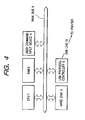
- Figs. 4 to 6 show the block diagrams showing the internal structures of the host computers respectively shown in Figs. 1 to 3.
- Reference numeral 1 represents a CPU
- 2 represents a RAM as a working area of CPU 1
- 3 represents a hard disk (or floppy disk, CD-ROM, MO, ROM, etc.) for storing programs
- 5 represents a Centronics port
- 51 represents a Centronics line to be connected to a printer
- 61 represents a USB line to be connected to a printer
- 71 represents an IEEE 1394 line to be connected to a printer
- 8 represents a main bus.
- CPU 1 of the host computer controls RAM 2, hard disk 3, Centronics port 5, a USB protocol controller 6, and an IEEE 1394 controller 7 respectively connected to the main bus 8.
- CPU 1 In executing each program, CPU 1 reads the program from the hard disk 3 and writes it in RAM 2, and CPU 1 reads the program from RAM 2 to execute it. Each time a process stage is changed, a different program is used.
- an application transmits data to a printer driver” and "a printer driver converts the data” are used. These sentences strictly mean that "CPU 1 processes data by using an application, and processes it thereafter by using the printer driver” and "CPU 1 converts data by using the printer driver".
- the program itself does not process, but the program used for processing is an application or a printer driver.
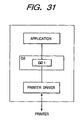
- the application As the application generates data, it inquires about the printer performance from GDI in order to determine the data format. GDI then inquires about the printer performance from the printer driver. When the printer performance is acquired, it is returned back to the application in the format of GDI function. This data is called a device context (DC). The application sends a transmission start signal to GDI, and GDI sends a transmission start signal to the printer driver.
- DC device context
- the application transmits data in the format of GDI function to GDI.
- GDI converts it in the format of DDI function and transmits the data to the printer driver.
- the printer driver converts the received data in the format of DDI function into PDL or image data in accordance with the connected interface type and printer type, and sends the converted data to the printer.
- the details thereof will be given in the following.
- the printer connection table is stored in RAM 2 and dynamically updated. Each time a new printer driver is installed, a printer name item is added. When the printer driver is installed, a line type is discriminated and stored in RAM 2.
- the line type can be discriminated through detection by the USB protocol controller 6 shown in Fig. 4, by the Centronics port 5 shown in Fig. 5 or by the IEEE 1394 controller 7 shown in Fig. 6. Specifically, the line type is discriminated by a user designation, by a Plug and Play function, or by an operating system.
- rasterization table shown in Fig. 8 will be described. This table is stationary present in the program of the invention, and developed on RAM 2 when the program is loaded.
- a user generates image data, character data or the like by using the application (S101).
- the description of this selection method is omitted because it is not directly relevant to the invention.
- the selection information (printer name and the like) of the printer is stored in RAM 2 (S103).
- the user notifies the application of a print start instruction, by using the user command input device 4 (S104).
- the printer selection information is read from RAM 2 (S105) and a corresponding printer driver is loaded in RAM 2 (S106).
- a rasterization level is determined with reference to the rasterization table shown in Fig. 8 (S109).
- This rasterization level is determined by referring to the rasterization table by using as parameters the printer name and line type stored in RAM 2.
- the determined rasterization level is stored in RAM 2 (S110).
- the received print command is stored in the hard disk 3 (S112).
- the print command is converted into print data (S113).
- Print data has a format which the printer can understand.
- a method of converting the print command into the print data by using the rasterization level will be described by taking graphical patterns such as shown in Fig. 10 as an example.
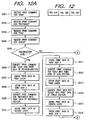
- the processes of printing four graphical patterns shown in Fig. 11, divided from the graphical patterns shown in Fig. 10 in response to the print command from the application, will be described with reference to the flow charts of Figs. 12A to 12C.
- the printer driver receives a print command for the rectangle graphical pattern from the application via GDI (S202), and stores it in the hard disk 3.
- the printer driver receives a print command for the oval graphical pattern from the application via GDI (S203), and stores it in the hard disk 3.
- the print command for the star graphical pattern is read from the hard disk 3, and converted into print data in a vector mode representing a polygon having apex coordinates (S206).
- the print data is defined as the first layer (lowest layer) (S207).
- the print data is stored in the hard disk 3 (S208).
- the print command for the rectangle graphical pattern is read from the hard disk 3, and converted into print data in a vector mode representing a rectangle (S209).
- the print data is stored in the hard disk 3 (S211)
- the print command for the oval graphical pattern is read from the hard disk 3, and converted into print data in a vector mode representing an oval (S212).
- the print data is defined as the third layer (S213).
- the print data is stored in the hard disk 3.
- the print command for the circle graphical pattern is read from the hard disk 3, and converted into print data in a vector mode representing a circle (S214).
- the print data is defined as the fourth layer (S215).
- the print data is stored in the hard disk 3 (S216).
- the print command for the star graphical pattern is read from the hard disk 3, and converted into print data of image data representing the star whose black/white of each bit is represented by binary or multi values (S218).
- the print data is defined as the first layer (lowest layer) (S219).
- the print command for the rectangle graphical pattern is read from the hard disk 3, and converted into print data in a vector mode representing a rectangle (S221).
- the print data is defined as the second layer (S222).
- the print data is stored in the hard disk 3 (S223).
- the print data is stored in the hard disk 3.
- the print command for the circle graphical pattern is read from the hard disk 3, and converted into print data in a vector mode representing a circle (S226).
- the print data is defined as the fourth layer (S227).
- the print data is stored in the hard disk 3 (S228).
- the print command for the star graphical pattern is read from the hard disk 3, and converted into print data of image data representing the star whose black/white of each bit is represented by binary or multi values (S230).
- the print data is stored in the hard disk 3 (S231).
- the print command for the rectangle graphical pattern is read from the hard disk 3, and converted into print data of image data representing the rectangle whose the black/white of each bit is represented by binary or multi values (S232).
- the print data is stored in the hard disk 3 (S233).
- the print command for the circle graphical pattern is read from the hard disk 3, and converted into print data of image data representing the circle whose black/white of each bit is represented by binary or multi values (S236).
- the print data is stored in the hard disk 3 (S237).
- the four image data are read from the hard disk 3 and superposed one upon another while considering the layers and transparency to form a single frame of image data (S238).
- the superposed image data is stored in the hard disk (S239).
- the line controllers 5 to 7 corresponding to the line type stored in RAM 2 is requested to transmit the print data to the printer (S115).
- the line controller 5 to 7 reads the print data from the hard disk 3 (S116), and transmits it via the designated line 19 to the printer (S117) to thereafter terminate the procedure (S118).
- the character data is all converted into print data of image data by the host computer, whereas if the level is lower than the predetermined value, for the character to be transmitted at the second time or later, only the data identifier is transmitted to the printer.
- This control method may be applied.
- host computers and printers are connected by RS-232C or so called Centronics.
- the transmission rate of such a line is often too low as compared to the processing capacity of a printer. It is therefore possible that a host computer generates print data, compresses it and transmits it and the printer expands the received compressed print data, and if necessary, performs a data conversion process and prints it out.
- the rasterization level may be used in determining from the line type whether the print data is to be compressed, and if compressed, what compression method is to be used. Namely, a plurality of compression methods are prepared in a printer, and the compression method is determined in accordance with the rasterization level.
- the transmission rate is predicted in accordance with the line type, and the rasterization level matching the predicted transmission rate is determined.
- isochronous transmission lines such as IEEE 1394
- the isochronous transmission bandwidth may be acquired before the print data is generated, and the rasterization level is determined in accordance with the acquired bandwidth (transmission rate).
- the bandwidth of isochronous transmission will be later described. The process of acquiring the bandwidth will be described with reference to Fig. 6.
- CPU 1 inquires about a bandwidth from the IEEE 1394 controller 7.
- the bandwidth is managed by RAM 2. Therefore, in response to the inquiry, the bandwidth is acquired from RAM 2.
- the IEEE 1394 controller 7 inquires about a bandwidth from the root. In response to this inquiry, the bandwidth information is returned back.
- the rasterization level is determined.
- the rasterization level is set to "3"
- the rasterization level is set to "2”
- the rasterization level is set to "3"
- the rasterization level can be determined from the bandwidth by referring to the judgement table.
- the print command is converted into print data similar to the first embodiment, and transmitted to the printer.
- the data transmission rate of IEEE 1394 can be changed and acquired in the similar manner to the bandwidth.
- the rasterization level may be determined therefore in accordance with the data transmission rate.
- the data transmission rates of IEEE 1394 include three rates of 100/200/400 bps as will be later described. If the transmission rate is 100 bps, the rasterization level is set to "1", if the transmission rate is 200 bps, the rasterization level is set to "2", and if the transmission rate is 400 bps, the rasterization level is set to "3". In this manner, the rasterization level may be determined.
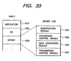
- a program realizing the functions of the first to fourth embodiments may be externally supplied to RAM 2 to embody the present invention by reading the program from RAM 2.
- This system configuration is shown in Fig. 33.
- RAM 2 stores an application 1010, an OS 1020, and an externally supplied printer driver 1030.
- the application 1010 is a module for generating original data based on which the print data is supplied to the printer, and supplying the original data to OS 1020.
- the format of this data supplied to OS 1020 is the GDI format described previously.
- OS processes this data at that time.
- OS 1020 is a module for converting the data of GDI formation supplied from the application into data of DDI format.
- the data of DDI format converted by the GDI 1020 is processed by the printer driver 1030.
- the printer driver 1030 is a module for converting the data of DDI format into PDL or image data and transmitting it to the printer. The details of the printer driver will be given in the following.
- the printer driver 1030 is constituted of an identification module 1031, a conversion control module 1032, a data conversion module 1033 and a transmission control module 1034.
- the identification module 1031 is a module for identifying the type of a line, the type of a printer, and if the connected line is IEEE 1394, a data transmission rate and a bandwidth usable for isochronous data transmission.
- the identification module 1031 executes S103 to S108 in the flow chart shown in Fig. 9.
- the process is passed to the next conversion control module 1032.
- the conversion control module 1032 is a module for determining a rasterization level in accordance with the type of a line, the type of a printer, the data transmission rate and bandwidth usable for isochronous data transmission.
- the conversion control module 1032 executes S109 to S110 in the flow chart shown in Fig. 9.
- the data conversion module 1033 is a module for converting the data of DDI format supplied from OS 1020 into image data or data of PDL format, in accordance with the designated rasterization level.
- the data conversion module 1033 executes S111 to S114 in the flow chart shown in Fig. 9.
- the transmission control module 1034 is a module for transmitting the converted image data or data of PDL format to the printer via the line controller 5 to 7.
- the transmission control module 1034 executes S115 to S117 in the flow chart shown in Fig. 9.
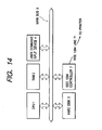
- Fig. 14 is a block diagram showing the internal structure of a host computer embodying the invention. Like elements to those shown in Fig. 6 are represented by identical reference numerals.
- Reference numeral 1 represents a CPU
- 2 represents a RAM as a working area of CPU 1
- 3 represents a hard disk (or floppy disk, CD-ROM, MO, ROM, magnetic tape, etc.) for storing programs
- 4 represents a user command input device
- 7 represents a line controller (in this example, IEEE 1394)
- 71 represents a line to be connected to a printer, the line being capable of isochronous data transmission (in this example, IEEE 1394)
- 8 represents a main bus.
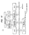
- Fig. 15 is a block diagram showing the internal structure of a printer embodying the invention.
- Reference numeral 17 represents a line controller (in this example, IEEE 1394).
- Reference numeral 171 represents a line to be connected to a printer, the line being capable of isochronous data transmission (in this example, IEEE 1394).
- Reference numeral 18 represents a main bus and 19 represents a mechanical controller for controlling a print mechanism of the printer.
- Reference numeral 22 represents a print data processor for processing received print data
- 20 represents a video I/F for storing image data converted from the print data
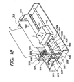
- 21 represents a printer engine for performing actual printing, the details of the printer engine being later given with reference to Figs. 18 and 19.
- Reference numeral 23 represents a processing speed sensor for detecting an operation speed of the printer engine.
- CPU 1 of the host computer controls RAM 2, hard disk 3, user command input device 4, and line controller 7 respectively connected to the main bus 8.
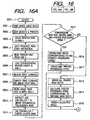
- a user generates image data, character data or the like by using an application or the like (S501).
- the user selects a desired printer by using the user command input device 4 (S502).
- the selection information (printer name and the like) of the printer is stored in RAM 2 (S503).
- the user notifies the application of a print start instruction, by using the user command input device 4 (S504).
- the printer selection information is read from RAM 2 (S505) and a corresponding printer driver is loaded in RAM 2 (S506).
- the application transmits a print command for the user generated image or character data to the printer driver.
- the printer driver Upon reception of the print command (S507), the printer driver converts the data into print data of image data corresponding to the print command (S508).
- the converted print data of image data is stored in the hard disk 3 (S509).
- the line controller 7 Upon reception of the isochronous transmission bandwidth, the line controller 7 confirms the line condition as to an unused bandwidth of the current line (S511).
- the bandwidth is managed by RAM 2. Therefore, in response to the inquiry about the bandwidth, it is acquired from RAM 2. If the host computer is connected in one-to-one correspondence to the printer, the host computer is automatically set to the root.
- the bandwidth is inquired to the root via the line controller 7 and network. In response to this inquiry, the bandwidth information is returned back.
- an expected transmission rate for print data of image data is calculated and compared with a maximum value (a value specific to the printer engine) of the operation speed of the printer engine.
- the maximum value of the printer engine operation speed is stored in RAM 2 in its "speed field" (S517).
- a printer engine operation speed is calculated so as to operate the printer engine at the acquired bandwidth (data transmission rate) (S514), and stored in RAM 2 in its "speed field” (S515).
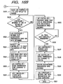
- the value in the "speed field" of RAM 2 is transmitted via the line controller 7 to the printer, in the format of asynchronous packet (S518).
- the print data of image data is transmitted (S526).
- the print data of image data is transmitted in the format of isochronous packet. This format will be later described.
- the line controller 7 After all the print data of image data is transmitted (S527), the line controller 7 transmits a print data transmission end command to the printer (S528).
- the acquired isochronous transmission bandwidth is released (S529).
- the line controller 7 notifies the data transmission end (S530) to terminate the procedure (S531).
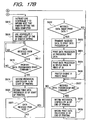
- An initializing process is first executed to make the printer idle (S601).
- the line controller 17 In order to notify the host computer of the print data reception preparation completion, the line controller 17 is instructed to transmit a setting completion notice to the host computer (S615). In response to this, the line controller 17 transmits the setting completion notice to the host computer (S616).
- the contents of data are checked to confirm whether the received data is the print data transmission start command (S618). If so, the mechanical controller 19 is instructed to start the print process (S619). The print data processor is also instructed to start the print process (S620). The line controller 17 waits for data to be transmitted from the host (S621).
- the print data processor executes processes necessary for the print data (S624) and writes the processed data in the video I/F (S625).
- the printer engine controlled by the mechanical controller transfers the image written in the video I/F to a printing sheet to print it out (S626).
- the received data is not print data, it is checked whether the received data is the print data transmission end command (S627). If so, it is judged that the print data reception and print process have been completed, and the mechanical controller 19 is notified of the print process end (S628). The print data processor is also notified of the print process end (S629) to thereafter return to the idle state (S602).
- the operation speed of the printer engine is controlled in accordance with the bandwidth of isochronous data transmission.
- the operation speed of the printer engine may be controlled in accordance with a data transmission rate. The control process thereof will be described in the following.
- the line controller 7 is inquired about a data transmission rate. This process is replaced by S510 to S516 of the fifth embodiment.
- the printer engine operation speed is calculated from the data transmission rate. This process is replaced by S517.
- the processes to follow are the same as those of the fifth embodiment.
- the data transmission rates are only three rates of 100/200/400 bps.
- the printer engine operation speed corresponding to each transmission rate is stored in a table. With reference to this table, the printer engine operation speed is changed with the transmission rate.
- the host computer acquires the bandwidth, and in accordance with this bandwidth, the printer engine operation speed is calculated and informed to the printer.
- the printer engine operation speed may be calculated on the side of the printer.
- the mechanical controller 19 controls the printer engine operation speed in accordance with the calculated operation speed.
- steps S514 and S515 of the fifth embodiment are executed by the printer.
- the printer not the "speed" but the isochronous data transmission bandwidth is transmitted.
- This embodiment can be applied not only to the case where the printer engine operation speed is calculated from the isochronous data transmission bandwidth but also to the case of the sixth embodiment wherein the printer engine operation speed is calculated from the data transmission rate.
- a printer to be applied to the invention embodiments is not limited to a laser beam printer and an ink jet printer, but other printers of different types may also be used obviously.
- Fig. 18 is a schematic cross sectional view of a first output apparatus applicable to the invention, e.g., a laser beam printer (LBP).
- LBP laser beam printer
- reference numeral 1500 represents an LBP which stores print information (character codes and the like), form information, macro instructions and the like supplied from an externally connected host computer, and in accordance with stored information, generates corresponding character patterns, form patterns and the like to print an image on a recording medium such as a recording sheet.
- Reference numeral 1501 represents an operation panel mounted with switches, LED display units and the like for the operation of LBP.
- Reference numeral 1000 represents a print control unit for controlling LBP 1500 and analyzing character information and the like supplied from the host computer. This print control unit 1000 converts mainly character information into video signals of character patterns and outputs them to a laser driver 1502.
- a carriage HC engages with a spiral groove 5004 of a lead screw 5005 which is rotated by drive force transmission gears 5011 and 5009 in association with the normal or reverse rotation of a drive motor 5013.
- the carriage HC has unrepresented pins and is moved reciprocally in arrow a and b directions.
- An ink jet cartridge IJC is mounted on this carriage HC.
- Reference numeral 5002 represents a paper pusher plate which pushes a recording sheet against a platen 5000 over the whole span of carriage motion.
- Reference numerals 5007 and 5008 represent photocouplers for detecting a presence of a carriage lever 5006 in this area and functioning as a home position detecting means used for switching rotation directions of the motor 5013 or for other operations.
- Reference numeral 5016 represents a support for supporting a cap member 5022 which caps the whole surface of a recording head.
- Reference numeral 5015 represents a suction means for sucking the inside of the cap member to perform suction recovery of the recording head via an opening 5023 in the cap member.
- Reference numeral 5017 represents a cleaning blade which is made movable back and forth with a member 5019.
- Reference numeral 5018 represents a support plate for supporting the blade 5017 and member 5019.
- Reference numeral 5012 represents a lever for initiating suction of the suction recovery, the lever being made movable by a cam 5020 engaging with the carriage so that a drive force of the drive motor is controlled by a know transmission means such as a clutch.
- reference numeral 1700 represents an interface for inputting a record signal supplied from a host computer.
- Reference numeral 1701 represents an MPU
- 1702 represents a ROM for storing control programs to be executed by MPU 1701 and host print information or the like
- 1703 represents a DRAM for storing various data such as the above-described record signal, and record data to be supplied to the head.
- Reference numeral 1704 represents a gate array for performing a control of supplying data to a recording head 1708, and also for data transmission control among the interface 1700, MPU 1701 and DRAM 1703.
- Reference numeral 1710 represents a carrier motor for transporting the recording head 1708
- 1709 represents a transport motor for transporting a recording sheet
- 1705 represents a head driver for driving the recording head
- 1706 represents a motor driver for driving the transport motor 1709
- 1707 represents a motor driver for driving the carrier motor 1710.
- the recording apparatus when data is input from a host computer via the interface 1700, the input data is converted into print data by the gate array 1704 and MPU 1701. As the motor drivers 1706 and 1707 are driven, the print data supplied to the head driver 1705 drives the recording head to print it out.
- IEEE 1394 serial busses are used for interconnection of respective apparatuses, an IEEE 1394 serial bus will be described.
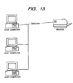
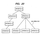
- Fig. 20 shows an example of a network system configured by using 1394 serial busses.
- This system has apparatuses A to H. Twist pair cables of 1394 serial bus are connected between A and B, between A and C, between B and D, between D and E, between C and F, between C and G and between C and H. Examples of these apparatuses are a PC, a digital VTR, a DVD, a digital camera, a hard disk, a monitor and the like.
- daisy chain and node branch are both used so that a high degree of connection freedom is possible.
- Each apparatus has its specific ID, and the apparatuses connected by 1394 serial busses confirm each ID to establish one network.
- the apparatuses are sequentially connected by 1394 serial bus cables, and each apparatus servers as a relay station among the apparatuses to configure a single network.
- each apparatus When each apparatus is connected by a 1394 serial bus, it can be automatically recognized and the connection state thereof can be recognized with the help of the Plug and Play function characteristic to the 1394 serial bus.
- the data transmission rates include 100/200/400 bps.
- the apparatus having a higher transmission rate supports the apparatus having a lower transmission rate to make them compatible.
- the data transmission mode includes an asynchronous transmission mode for transmitting asynchronous data (hereinafter called Async data) such as control signals and an isochronous transmission mode for transmitting isochronous data (hereinafter called Iso data) such as real time video and audio data.
- Async data asynchronous data
- Iso data isochronous data
- the Iso data is transmitted with a priority over the Async data in each cycle (generally 125 ⁇ s), after a cycle start packet (CSP) indicating the start of a cycle is transmitted.
- CSP cycle start packet
- the 1394 serial bus is configured to have a layer (hierarchical) structure. As shown in Fig. 21, the constituent most like hardware is the 1394 serial bus cable which is connected to a 1394 connector port on which a physical layer and a link layer are formed as hardware.
- the hardware portion is substantially an interface chip.
- the physical layer performs coding and connector control
- the link layer performs packet transmission and cycle time control.
- An application layer of the software portion becomes different depending upon software to be used. This layer defines how data is placed on an interface, in accordance with a protocol such as an AV protocol.
- Fig. 22 shows an address space of the 1394 serial bus.
- each apparatus (node) connected to the 1394 serial bus has a 64-bit address specific to its node. This address is stored in ROM so that the node address of its own or a partner node can be recognized always to allow communications with a designated partner.
- Addressing of the 1394 serial bus incorporates a scheme in conformity with IEEE 1212 specifications. In addressing, the first 10 bits are used for designating a bus number, and the next 6 bits are used for designating the node ID. The remaining 48 bits form an address width assigned to the apparatus and can be used as a specific address space. The last 28 bits are used as a specific data area in which information of apparatus discrimination and use condition designation is stored.
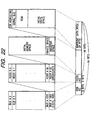
- Fig. 23 is a cross sectional view of a 1394 serial bus cable.
- a power supply voltage at the power line is 8 to 40 V, and a current is DC 1.5 A at a maximum.
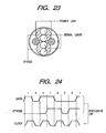
- Fig. 24 illustrates a DS-Link (Data/Strobe Link) coding scheme for a data transmission format adopted by the 1394 serial bus.
- DS-Link Data/Strobe Link
- the 1394 serial bus adopts the DS-Link coding scheme.
- This DS-Link coding scheme is suitable for high speed serial data communications. It is necessary to use two pairs of signal lines. One pair of two twist pair signal lines is used for transmitting main data, and the other of two twist pair signal lines is used for transmitting a strobe signal.
- a clock can be retrieved by an exclusive logical sum of the transmitted data and strobe.
- the merits of the DS-Link coding scheme are as follows. A transmission efficiency is higher than other serial data transmission methods. Since a PLL circuit is not necessary, the scale of a controller LSI can be made small. Since it is not necessary to transmit information representative of an idle state when there is no data to be transmitted, a transceiver circuit of each equipment can enter a sleep state and a power consumption can be lowered.
- the data in a packet format is transmitted.
- the node received the data returns back an ack (reception confirmation return code) after a short ack gap, or returns a response packet to complete the data transmission.
- the ack is constituted of four-bit information and four-bit check sums including information of a success, failure, or pending state, and is returned immediately to the transmission source node.
- Fig. 27 shows an example of the packet format used by the asynchronous transmission.
- the packet includes a header field in addition to a data field and error correction data CRC.
- the header field is written with, as shown in Fig. 27, an object node ID, a source node ID, a transmission data length, and various codes to transmit them.
- the asynchronous transmission is one-to-one communications between its own node and a partner node.
- a packet transmitted from the transmission source node is transmitted to each node of the network. However, the packet transmitted to each node and not having an address of the node is discarded, so that only one node having the object node address can read the packet.
- the isochronous transmission transmits data synchronously.
- the most characteristic feature of the 1394 serial bus is this isochronous transmission. This mode is suitable particularly for real time data transmission required for multi media data such as video and audio data.
- this isochronous transmission can broadcast a packet from one transmission source to all other nodes, by using the broadcast function.
- Fig. 28 shows a time sequential transition during the asynchronous transmission.
- the isochronous transmission is executed on the bus at a predetermined time interval. This time interval is called an isochronous cycle which is 125 ⁇ s.
- a cycle start packet shows a start time of each cycle and has a roll of adjusting time at each node.
- the cycle start packet is transmitted by a node called a cycle master.
- the cycle start packet indicating the start of a cycle is transmitted after a predetermined idle period (subaction gap) after the transmission in the preceding cycle is completed.
- the cycle start packet is transmitted at a time interval of 125 ⁇ s.
- a plurality of packets in channels A, B and C such as shown in Fig. 28 can be transmitted during one cycle in a discriminated manner by assigning each packet with a channel ID. It is therefore possible to transmit a plurality of packets to a plurality of nodes in real time and to receive the data having only a desired channel ID.
- This channel ID does not indicate the object node address, but it is only a logical number of data. Therefore, each packet is transmitted from one source node to all other nodes, i.e., the packet is broadcast.
- arbitration Prior to transmitting a packet through isochronous transmission, arbitration is performed similar to the asynchronous transmission. Since the isochronous transmission is not one-to-one communications like the asynchronous transmission, the ack (reception confirmation return code) is not used for the isochronous transmission.
- An iso gap (isochronous gap) shown in Fig. 28 is an idle period necessary for confirming before the isochronous transmission that the bus is idle. After this predetermined idle period lapses, a node intending to perform isochronous transmission judges that the bus is idle and can perform arbitration before the transmission.
- Fig. 29 shows an example of the format of a packet used by the isochronous transmission.
- Each packet in each channel includes a header field in addition to a data field and error correction data CRC.
- the header field is written with, as shown in Fig. 29, a transmission data length, a channel number, various other codes, and an error correction header CRC to transmit them.
- the isochronous transmission has been described above.
- Fig. 30 shows a time sequential transition of both the isochronous and asynchronous transmissions on the bus.
- the isochronous transmission is performed with a priority over the asynchronous transmission.
- the reason for this is that the isochronous transmission can be performed after the cycle start packet, with a shorter gap length (isochronous gap) than a gap length (subaction gap) of the idle period necessary for performing the asynchronous transmission.
- the isochronous transmission is therefore performed with a priority over the asynchronous transmission.
- a cycle start packet is transmitted from the cycle master to each node.
- Each node performs time adjustment.
- a node intending to perform isochronous transmission carries out arbitration to transmit a packet.
- a channel e, a channel s and a channel k are used in this order for the isochronous transmission.
- the period while the asynchronous transmission can be performed, is limited only when the subaction gap for the asynchronous transmission is obtained until the cycle synch time for transmitting the next cycle start packet.
- the isochronous transmissions for three channels are performed and thereafter the asynchronous transmissions (including ack) for two packets (packets 1 and 2) are performed.
- the asynchronous packet 2 it is the time (cycle synch) when the cycle (m+1) starts so that the transmission in the cycle #m terminates at this time.
- next cycle start packet is transmitted. Namely, if the one cycle continues longer than 125 ⁇ s, the next cycle is made shorter than 125 ⁇ s correspondingly. In this manner, the cycle time can be elongated or shortened relative to 125 ⁇ s.
- the isochronous transmission is always executed in each cycle, if necessary, in order to preserve the real time transmission, whereas the asynchronous transmission may be passed to the next or following cycle if the cycle time is shortened.
- the data transmission rate can be made optimum in accordance with the line capacity.
- the host computer if a line having a high transmission rate is used, the host computer generates data so as to minimize data conversion at the printer. Although the data amount increases, it takes not so long a time to transmit data because the line is high speed, and a load of a data conversion process at the printer is reduced. It is therefore possible for a user to obtain a printed sheet in a short time.
- a load distribution is controlled in accordance with the bandwidth of isochronous transmission.
- the processing capacity of a printer and a line transmission capacity are adjusted properly.
- the line transmission capacity corresponds to the isochronous transmission bandwidth in the case of the fifth embodiment, and to the data transmission rate in the case of the sixth embodiment.
- the line isochronous transmission bandwidth is acquired as small as possible to match the print operation speed, so that the bandwidth is not acquired unnecessarily large. Adverse effects on other communications on the same line can therefore be minimized.
- the reception data amount per unit time at a printer is balanced with a print data amount, it is not necessary to buffer the received print data.
- the printer is not therefore required to have many memories.
- the processing capacity of a printer is higher than the data transmission capacity, all the isochronous transmission bandwidth which can be acquired is used for the data transmission.
- the use efficiency of the isochronous transmission line resource becomes very high. A user can therefore obtain a printed sheet or the like in a shortest time. If the print process is performed at the highest operation speed of the printer, the data transmission lags behind the print operation and overrun occurs. In order to avoid this, the print operation speed is controlled in accordance with the data transmission rate. It is therefore possible to print data at a most proper speed in an allowable range of the processing capacity of a printer and the data transmission rate.
- a rasterization level is determined in accordance with a data transmission capacity of the communications unit, print data is generated at the determined rasterization level, and the generated data is transmitted to the printer.
Landscapes
- Engineering & Computer Science (AREA)
- Theoretical Computer Science (AREA)
- General Engineering & Computer Science (AREA)
- Computer Networks & Wireless Communication (AREA)
- Signal Processing (AREA)
- Business, Economics & Management (AREA)
- General Physics & Mathematics (AREA)
- Physics & Mathematics (AREA)
- Accounting & Taxation (AREA)
- Human Computer Interaction (AREA)
- Strategic Management (AREA)
- Finance (AREA)
- General Business, Economics & Management (AREA)
- Computer Hardware Design (AREA)
- Accessory Devices And Overall Control Thereof (AREA)
- Record Information Processing For Printing (AREA)
- Computer And Data Communications (AREA)
Applications Claiming Priority (3)
| Application Number | Priority Date | Filing Date | Title |
|---|---|---|---|
| JP6815997A JPH10260798A (ja) | 1997-03-21 | 1997-03-21 | 情報処理装置及び方法、出力制御装置及び方法、情報処理システム |
| JP68159/97 | 1997-03-21 | ||
| JP6815997 | 1997-03-21 |
Publications (3)
| Publication Number | Publication Date |
|---|---|
| EP0866398A2 EP0866398A2 (en) | 1998-09-23 |
| EP0866398A3 EP0866398A3 (en) | 2002-04-03 |
| EP0866398B1 true EP0866398B1 (en) | 2006-09-27 |
Family
ID=13365709
Family Applications (1)
| Application Number | Title | Priority Date | Filing Date |
|---|---|---|---|
| EP98105166A Expired - Lifetime EP0866398B1 (en) | 1997-03-21 | 1998-03-21 | Data transmission control in accord with line capacity |
Country Status (4)
| Country | Link |
|---|---|
| US (1) | US6249835B1 (enExample) |
| EP (1) | EP0866398B1 (enExample) |
| JP (1) | JPH10260798A (enExample) |
| DE (1) | DE69835971D1 (enExample) |
Families Citing this family (30)
| Publication number | Priority date | Publication date | Assignee | Title |
|---|---|---|---|---|
| JPH1173488A (ja) * | 1997-08-29 | 1999-03-16 | Fuji Photo Film Co Ltd | 画像印刷システムおよび画像印刷方法 |
| JP3884862B2 (ja) * | 1998-04-30 | 2007-02-21 | キヤノン株式会社 | データ転送装置、データ転送装置の制御方法、記憶媒体 |
| JP2000108468A (ja) * | 1998-10-07 | 2000-04-18 | Fuji Photo Film Co Ltd | プリンター |
| US7203787B2 (en) * | 1999-01-25 | 2007-04-10 | Canon Kabushiki Kaisha | Information processing apparatus and method that utilizes stored information about a mountable device |
| US7437483B1 (en) * | 1999-03-24 | 2008-10-14 | Microsoft Corporation | System and method for transferring a compressed data file to a peripheral device |
| NL1018883C2 (nl) * | 2001-09-04 | 2003-03-05 | Neopost Ind B V | Werkwijze en stelsel van instructies voor het gedoseerd toevoeren van afdrukinstructies aan een printer alsmede systeem voor het toepassen van de werkwijze. |
| JP4235347B2 (ja) * | 1999-06-29 | 2009-03-11 | キヤノン株式会社 | 情報処理装置、情報処理方法、および記憶媒体 |
| JP2001287414A (ja) * | 2000-04-05 | 2001-10-16 | Sony Corp | データ変換装置及び方法、印刷装置及び方法、印刷制御装置及び方法、印刷システム及び印刷方法、データ伝送方法 |
| US6454174B1 (en) | 2000-05-19 | 2002-09-24 | Pitney Bowes Inc. | Method for reading electronic tickets |
| US6538757B1 (en) | 2000-05-19 | 2003-03-25 | Pitney Bowes Inc. | Method for automatically reading electronic tickets |
| JP4337246B2 (ja) * | 2000-08-29 | 2009-09-30 | コニカミノルタビジネステクノロジーズ株式会社 | 印刷オブジェクト変換装置、印刷オブジェクト変換方法、印刷オブジェクト変換方法に関するプログラムを記録するコンピュータ読取り可能な記録媒体 |
| US7315685B1 (en) * | 2000-10-16 | 2008-01-01 | Elbex Video Ltd. | Method and apparatus for continuous feed of disks for recording digital video signals and authenticating the digitally recorded disks |
| US7295751B2 (en) * | 2000-10-16 | 2007-11-13 | Elbex Video Ltd. | Method and apparatus for continuous feed of disks for recording digital video signals and authenticating the digitally recorded disks |
| US11204729B2 (en) | 2000-11-01 | 2021-12-21 | Flexiworld Technologies, Inc. | Internet based digital content services for pervasively providing protected digital content to smart devices based on having subscribed to the digital content service |
| US10860290B2 (en) | 2000-11-01 | 2020-12-08 | Flexiworld Technologies, Inc. | Mobile information apparatuses that include a digital camera, a touch sensitive screen interface, support for voice activated commands, and a wireless communication chip or chipset supporting IEEE 802.11 |
| US10915296B2 (en) | 2000-11-01 | 2021-02-09 | Flexiworld Technologies, Inc. | Information apparatus that includes a touch sensitive screen interface for managing or replying to e-mails |
| US7953818B2 (en) | 2000-11-20 | 2011-05-31 | Flexiworld Technologies, Inc. | Output device and system for rendering digital content |
| US20020097417A1 (en) | 2001-01-19 | 2002-07-25 | Chang William Ho | System for universal data output |
| JP2003196048A (ja) * | 2001-12-26 | 2003-07-11 | Nissei Plastics Ind Co | 射出成形機のデータ印刷方法 |
| US7463376B2 (en) * | 2002-01-30 | 2008-12-09 | Hewlett-Packard Development Company, L.P. | Print finishing method and apparatus |
| US20030174141A1 (en) * | 2002-03-14 | 2003-09-18 | Letellier Nolan Wayne | Sorting image primitives in generation of image page descriptions |
| US20040012797A1 (en) * | 2002-07-16 | 2004-01-22 | Letellier Nolan Wayne | Load balancing in image generation |
| US20040043674A1 (en) * | 2002-08-28 | 2004-03-04 | Dunne Denise E. | DSX jack including contact |
| JP4181881B2 (ja) * | 2003-01-22 | 2008-11-19 | キヤノン株式会社 | 画像処理装置および方法 |
| US7145669B2 (en) * | 2003-01-28 | 2006-12-05 | Hewlett-Packard Development Company, L.P. | Partially pre-rasterizing image data |
| JP4165451B2 (ja) * | 2003-08-11 | 2008-10-15 | セイコーエプソン株式会社 | 印刷システム、印刷要求端末および圧縮アルゴリズム選択プログラム、並びに印刷方法 |
| JP3994984B2 (ja) * | 2004-05-06 | 2007-10-24 | コニカミノルタビジネステクノロジーズ株式会社 | プリント支援モジュール、記録媒体及びプリントジョブ発行方法 |
| US8437020B2 (en) * | 2004-05-13 | 2013-05-07 | Sharp Laboratories Of America, Inc. | System and method for printer emulation |
| US8314961B1 (en) * | 2007-01-18 | 2012-11-20 | Marvell International Ltd. | Method and apparatus for printing raster page |
| JP2011178117A (ja) * | 2010-03-03 | 2011-09-15 | Fuji Xerox Co Ltd | 画像形成装置、及び給紙装置互換判定処理プログラム |
Family Cites Families (11)
| Publication number | Priority date | Publication date | Assignee | Title |
|---|---|---|---|---|
| US4701841A (en) * | 1984-07-25 | 1987-10-20 | Digital Equipment Corporation | System for altering data transmission modes |
| US5179692A (en) * | 1985-08-07 | 1993-01-12 | Seiko Epson Corporation | Emulation device for driving a LCD with signals formatted for a CRT display |
| JPS6391796A (ja) * | 1986-10-06 | 1988-04-22 | シャープ株式会社 | 印字フオ−マツトの変更方式 |
| JP2703914B2 (ja) * | 1988-01-19 | 1998-01-26 | キヤノン株式会社 | 文書画像処理装置 |
| US5845144A (en) * | 1991-12-25 | 1998-12-01 | Canon Kabushiki Kaisha | Information processing apparatus with internal printer |
| US5471563A (en) * | 1992-07-10 | 1995-11-28 | Microsoft Corporation | System and method for automatic resolution reduction |
| US5475686A (en) * | 1992-12-28 | 1995-12-12 | Motorola, Inc. | Method and apparatus for transferring data in a communication system |
| US5524184A (en) * | 1993-08-04 | 1996-06-04 | Monarch Marking Systems, Inc. | On-line barcode printer with automatic communication parameter determining system |
| US5577172A (en) * | 1994-07-01 | 1996-11-19 | Lasermaster Corporation | High-capacity protocol for packet-based networks |
| US5671440A (en) * | 1994-08-08 | 1997-09-23 | Eastman Kodak Company | Color image data reorientation and format conversion system |
| US5966451A (en) * | 1997-02-20 | 1999-10-12 | Kabushiki Kaisha Toshiba | Distributed network computing system, and data exchange apparatus and method and storage medium used in this system |
-
1997
- 1997-03-21 JP JP6815997A patent/JPH10260798A/ja active Pending
-
1998
- 1998-03-19 US US09/044,019 patent/US6249835B1/en not_active Expired - Lifetime
- 1998-03-21 DE DE69835971T patent/DE69835971D1/de not_active Expired - Lifetime
- 1998-03-21 EP EP98105166A patent/EP0866398B1/en not_active Expired - Lifetime
Also Published As
| Publication number | Publication date |
|---|---|
| US6249835B1 (en) | 2001-06-19 |
| JPH10260798A (ja) | 1998-09-29 |
| EP0866398A3 (en) | 2002-04-03 |
| EP0866398A2 (en) | 1998-09-23 |
| DE69835971D1 (de) | 2006-11-09 |
Similar Documents
| Publication | Publication Date | Title |
|---|---|---|
| EP0866398B1 (en) | Data transmission control in accord with line capacity | |
| US7283262B2 (en) | Image forming apparatus and power control method | |
| JP3927647B2 (ja) | 情報処理装置、情報処理方法及び情報処理システム | |
| EP0825552B1 (en) | Image forming apparatus, and control apparatus and method therefor | |
| JP2002120412A (ja) | 画像処理方法、印刷制御装置、プログラム及び記憶媒体 | |
| US6775020B2 (en) | Information processing apparatus and method of processing information | |
| US6359698B1 (en) | Printing apparatus and printing control method for printing the smallest received job first | |
| US6636327B2 (en) | Image processing apparatus and method | |
| US6831753B1 (en) | Printing apparatus, print control method, and recording medium storing print control program therein | |
| US6499069B1 (en) | Interface apparatus and method, and image output apparatus having interface apparatus | |
| US7173723B1 (en) | Printer and print system capable of printing a read image without intervention of host in addition to printing of print data from host | |
| US7352482B2 (en) | Apparatus and method for processing data and printing the same, and recording medium | |
| JP2000187579A (ja) | 印刷システム及び印刷装置、印刷制御方法、記録媒体 | |
| JP2001067193A (ja) | 印刷システム及び印刷装置及びその制御方法 | |
| JPH11143665A (ja) | 印刷制御システム及び方法 | |
| JPH09179809A (ja) | 論理チャネル利用制御方法 | |
| JPH10228364A (ja) | データ転送装置及びその制御方法及び印刷システム | |
| JP2001202208A (ja) | プリントシステム、印刷制御装置、および、プリンタ | |
| JPH11203067A (ja) | プリンタ制御システム、プリンタ、ホストコンピュータ、印刷方法および記憶媒体 | |
| JPH08282064A (ja) | 記録装置及び記録制御方法 | |
| JP2000043345A (ja) | 印刷システム及び印刷方法 | |
| JPH10226138A (ja) | プリンタ制御装置及び方法及びプリントシステム | |
| JPH11221944A (ja) | 印刷装置及び印刷システム | |
| JPH08272559A (ja) | 情報処理装置 | |
| JPH07334321A (ja) | 印刷装置及びその制御装置、及び印刷装置の制御方法 |
Legal Events
| Date | Code | Title | Description |
|---|---|---|---|
| PUAI | Public reference made under article 153(3) epc to a published international application that has entered the european phase |
Free format text: ORIGINAL CODE: 0009012 |
|
| AK | Designated contracting states |
Kind code of ref document: A2 Designated state(s): AT BE CH DE DK ES FI FR GB GR IE IT LI LU MC NL PT SE Kind code of ref document: A2 Designated state(s): DE FR GB IT NL |
|
| AX | Request for extension of the european patent |
Free format text: AL;LT;LV;MK;RO;SI |
|
| PUAL | Search report despatched |
Free format text: ORIGINAL CODE: 0009013 |
|
| AK | Designated contracting states |
Kind code of ref document: A3 Designated state(s): AT BE CH DE DK ES FI FR GB GR IE IT LI LU MC NL PT SE |
|
| AX | Request for extension of the european patent |
Free format text: AL;LT;LV;MK;RO;SI |
|
| 17P | Request for examination filed |
Effective date: 20020814 |
|
| AKX | Designation fees paid |
Free format text: DE FR GB IT NL |
|
| 17Q | First examination report despatched |
Effective date: 20050314 |
|
| GRAP | Despatch of communication of intention to grant a patent |
Free format text: ORIGINAL CODE: EPIDOSNIGR1 |
|
| GRAS | Grant fee paid |
Free format text: ORIGINAL CODE: EPIDOSNIGR3 |
|
| GRAA | (expected) grant |
Free format text: ORIGINAL CODE: 0009210 |
|
| AK | Designated contracting states |
Kind code of ref document: B1 Designated state(s): DE FR GB IT NL |
|
| PG25 | Lapsed in a contracting state [announced via postgrant information from national office to epo] |
Ref country code: NL Free format text: LAPSE BECAUSE OF FAILURE TO SUBMIT A TRANSLATION OF THE DESCRIPTION OR TO PAY THE FEE WITHIN THE PRESCRIBED TIME-LIMIT Effective date: 20060927 Ref country code: IT Free format text: LAPSE BECAUSE OF FAILURE TO SUBMIT A TRANSLATION OF THE DESCRIPTION OR TO PAY THE FEE WITHIN THE PRE;WARNING: LAPSES OF ITALIAN PATENTS WITH EFFECTIVE DATE BEFORE 2007 MAY HAVE OCCURRED AT ANY TIME BEFORE 2007. THE CORRECT EFFECTIVE DATE MAY BE DIFFERENT FROM THE ONE RECORDED.SCRIBED TIME-LIMIT Effective date: 20060927 |
|
| REG | Reference to a national code |
Ref country code: GB Ref legal event code: FG4D |
|
| REF | Corresponds to: |
Ref document number: 69835971 Country of ref document: DE Date of ref document: 20061109 Kind code of ref document: P |
|
| PG25 | Lapsed in a contracting state [announced via postgrant information from national office to epo] |
Ref country code: DE Free format text: LAPSE BECAUSE OF FAILURE TO SUBMIT A TRANSLATION OF THE DESCRIPTION OR TO PAY THE FEE WITHIN THE PRESCRIBED TIME-LIMIT Effective date: 20061228 |
|
| NLV1 | Nl: lapsed or annulled due to failure to fulfill the requirements of art. 29p and 29m of the patents act | ||
| EN | Fr: translation not filed | ||
| PLBE | No opposition filed within time limit |
Free format text: ORIGINAL CODE: 0009261 |
|
| STAA | Information on the status of an ep patent application or granted ep patent |
Free format text: STATUS: NO OPPOSITION FILED WITHIN TIME LIMIT |
|
| 26N | No opposition filed |
Effective date: 20070628 |
|
| PG25 | Lapsed in a contracting state [announced via postgrant information from national office to epo] |
Ref country code: FR Free format text: LAPSE BECAUSE OF FAILURE TO SUBMIT A TRANSLATION OF THE DESCRIPTION OR TO PAY THE FEE WITHIN THE PRESCRIBED TIME-LIMIT Effective date: 20070525 |
|
| PG25 | Lapsed in a contracting state [announced via postgrant information from national office to epo] |
Ref country code: FR Free format text: LAPSE BECAUSE OF FAILURE TO SUBMIT A TRANSLATION OF THE DESCRIPTION OR TO PAY THE FEE WITHIN THE PRESCRIBED TIME-LIMIT Effective date: 20060927 |
|
| PGFP | Annual fee paid to national office [announced via postgrant information from national office to epo] |
Ref country code: GB Payment date: 20140318 Year of fee payment: 17 |
|
| GBPC | Gb: european patent ceased through non-payment of renewal fee |
Effective date: 20150321 |
|
| PG25 | Lapsed in a contracting state [announced via postgrant information from national office to epo] |
Ref country code: GB Free format text: LAPSE BECAUSE OF NON-PAYMENT OF DUE FEES Effective date: 20150321 |