EP0865745A2 - Schublade - Google Patents
Schublade Download PDFInfo
- Publication number
- EP0865745A2 EP0865745A2 EP98104530A EP98104530A EP0865745A2 EP 0865745 A2 EP0865745 A2 EP 0865745A2 EP 98104530 A EP98104530 A EP 98104530A EP 98104530 A EP98104530 A EP 98104530A EP 0865745 A2 EP0865745 A2 EP 0865745A2
- Authority
- EP
- European Patent Office
- Prior art keywords
- drawer
- frames
- parts
- sections
- drawer according
- Prior art date
- Legal status (The legal status is an assumption and is not a legal conclusion. Google has not performed a legal analysis and makes no representation as to the accuracy of the status listed.)
- Granted
Links
- 238000004873 anchoring Methods 0.000 claims description 6
- 239000000463 material Substances 0.000 claims description 4
- 230000000284 resting effect Effects 0.000 abstract 1
- 238000010586 diagram Methods 0.000 description 6
- 101150114468 TUB1 gene Proteins 0.000 description 3
- 230000008878 coupling Effects 0.000 description 1
- 238000010168 coupling process Methods 0.000 description 1
- 238000005859 coupling reaction Methods 0.000 description 1
- 238000002347 injection Methods 0.000 description 1
- 239000007924 injection Substances 0.000 description 1
- 239000002184 metal Substances 0.000 description 1
Images


Classifications
-
- A—HUMAN NECESSITIES
- A47—FURNITURE; DOMESTIC ARTICLES OR APPLIANCES; COFFEE MILLS; SPICE MILLS; SUCTION CLEANERS IN GENERAL
- A47B—TABLES; DESKS; OFFICE FURNITURE; CABINETS; DRAWERS; GENERAL DETAILS OF FURNITURE
- A47B88/00—Drawers for tables, cabinets or like furniture; Guides for drawers
- A47B88/90—Constructional details of drawers
- A47B88/944—Drawers characterised by the front panel
- A47B88/95—Drawers characterised by the front panel characterised by connection means for the front panel
-
- A—HUMAN NECESSITIES
- A47—FURNITURE; DOMESTIC ARTICLES OR APPLIANCES; COFFEE MILLS; SPICE MILLS; SUCTION CLEANERS IN GENERAL
- A47B—TABLES; DESKS; OFFICE FURNITURE; CABINETS; DRAWERS; GENERAL DETAILS OF FURNITURE
- A47B2210/00—General construction of drawers, guides and guide devices
- A47B2210/02—Drawers with hollow lateral walls in two parts
Definitions
- the invention relates to a drawer with two double-walled drawer frames, in which profile parts made of a plastic material are included extend over the entire length of the drawer frames.
- Such a drawer is known from AT 355 756 B.
- the drawer frame made of relatively thin material is stiffened, which contributes significantly to the stability of the drawer frame. It is advantageous the pull-out guide is partially integrated into the profile part or anchored to it. With such a drawer, the anchoring of a front panel is also the Drawer possible on the profile parts.
- the object of the invention is the in a drawer of the type mentioned Hold the profile parts in the drawer frames in the pull-out direction of the drawer improve.
- the object of the invention is achieved in that the profile parts front cover plates have, which rest on the end faces of the drawer frames and that at the rear ends of the profile parts holding elements are provided, which on the Drawer frames are pushed on and anchored in the profile parts.
- the Profile parts consist of separate front and rear sections that make up the front and have rear cover plates with which they are attached to the front and rear Front sides of the drawer frames rest, and the one another by means of hooks or the like can be coupled.
- the rear sections form with the rear cover plates Holding elements.
- the profile parts formed by the sections thus extend over the entire Length of each drawer frame and protrude slightly from the ends out. They are supported on the drawer frames at the front and rear.
- the drawer frames can also be part of a tub that covers the entire receiving space the drawer forms.
- Tub and drawer frames are examples injection molded in one piece from plastic material or deep drawn from a sheet.
- the cover plates grooves have, in which the ends of the drawer frames are received.
- Another embodiment of the invention provides that the rear sections with a hollow chamber open at the top for holding retaining pins for a rear wall increase are trained.
- At least some of the hooks that couple the sections are spring-formed, so that it is sufficient to push the sections into each other in order to close them together connect.
- the sections each advantageously have two hooks arranged one above the other, that point in opposite directions.
- the rear sections with slidable or pivotable in a vertical plane Holding parts are provided, each in a flange of the outer wall Snap the drawer frames into place.
- the holding parts of slides are advantageous or swivel levers formed, the sloping stop surfaces for the front Have sections.
- An embodiment of the invention provides that the holding elements are preferably wedge-shaped sliders are formed between the profile parts and the Drawer frames are inserted.
- Another embodiment of the invention provides that the holding elements of rocker arms are rotatably mounted on the profile parts.
- the drawer according to the invention essentially consists of a tub 1, Metal or plastic on which the drawer frames 8 are molded.
- the drawer frames 8 are hollow chamber profiles with an inner wall 8 'and an outer wall 8 ''. The profile parts are inserted into the drawer frames 8.
- the profile parts consist of two sections 2, 3.
- the sections 2, 3, which are preferably formed by plastic profiles, have front and rear connection plates 19, 20 on the inside are provided with grooves 21 which receive the edges of the drawer frames 8 and thus contribute to a further stiffening of the drawer frames 8 or the tub 1.
- the sections 2, 3 also have vertical struts 22 which have the cross section of the Drawer frames 8 correspond and stiffen the drawer frames 8.
- the sections 2, 3 are provided with hooks 9, 10 and 13, 14, by means of which the sections 2, 3 can be coupled together.
- the hooks 9, 10, 13, 14 are one above the other arranged, the hooks 10, 13 of the front section 2 facing each other are, while the hooks 9, 14 of the rear section 3 in opposite Show directions.
- a pivot lever 15 or a slider 16 is mounted at the rear section 3 at the rear section 3 at the rear section 3 at the rear section 3 is in advantageous embodiments of the invention below of the lower hook 14, a pivot lever 15 or a slider 16 is mounted. Of the Swivel lever 15 or the slider 16 protrudes downward into a flange 23 Outer wall 8 '' of the drawer frame 8. Both the pivot lever 15 and the Sliders 16 are provided with inclined surfaces 24, 24 'on which the hook 13 of the front Part 2 rests with a counter surface 25. This will cause the Parts 2, 3 of the pivot lever 15 and the slider 16 down into the flare 23 pressed.
- a chamber 26 open to the front is formed, in the anchoring means 12 arranged for the brackets 11 of a front panel, not shown are.
- the front section 2 has a side opening that gives access of a screwdriver to the anchoring means 12. This opening will covered by a removable cap 4.
- the rear sections 3 have hollow chambers 5 open at the top, into the anchoring pins 28 a return wall increase 6 can be inserted.
- railings 7 can be fastened in a conventional manner.
- the profile parts 30 are in one piece executed. In both exemplary embodiments, they have cover plates at their front ends 19 on the front side of the drawer frames 8. The cover plates 19 are in turn on their side facing the drawer frame 8 with a Provide groove 21 in which the end of the respective drawer frame 8 is received.
- the profile parts 30 of the embodiment according to the 14 to 16 have a recess 31 which is open towards the rear and upwards.
- a wedge-shaped slide 45 is inserted when the drawer is installed, which has a hook 27 at its front end and at its rear end a base 29 with a slot 32.
- the base 29 surrounds in the mounting position the outer rear end of the drawer frame 8.
- the profile part 30 has a smaller recess 33 and below the recess 31 a hole 34 on.
- the slider 25 engages with its hook 27 in the recess 33.
- the slide 25 is forward, i.e. inserted into the drawer frame 8 until its hook 27 in the hole 34 of the profile part snaps into place.
- the profile part 30 is thus at the front over the cover plate 19 and the groove 21 and fixed in the drawer frame 8 via the slide 45.
- the profile parts 30 is on its rear End provided with a base or projection 18 on which a rocker arm 35 by means an axis 36 supports.
- the rocker arm 35 has an arm 37 pointing upwards, which is provided at its free end with a slot 38 which the groove 32 of the Slider 25 corresponds. In the assembly position, the rear end of the Drawer frame 8 in this slot 38, so that the drawer frame 8 from the rocker arm 35 is held positively.
- An arm 39 projects from the arm 37 and is provided with a hook 40.
- the hook 40 snaps behind a projection 41 on the profile part 30 so that the rocker arm 35 is locked in the position in which it is the drawer frame 8 on the profile part 30 and the profile part 30 on the drawer frame 8 holds.
Landscapes
- Drawers Of Furniture (AREA)
- Valve Device For Special Equipments (AREA)
- Combinations Of Kitchen Furniture (AREA)
Abstract
Description
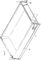
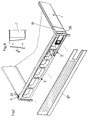
- Die Fig. 1
- ein Schaubild einer erfindungsgemäßen Schublade,
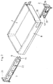
- die Fig. 2
- ein Schaubild einer erfindungsgemäßen Schublade, wobei die einen Profilteil bildenden Teilstücke aus der Schubladenzarge herausgezogen gezeichnet sind,
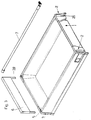
- die Fig. 3
- ein weiteres Schaubild einer erfindungsgemäßen Schublade mit einer Rückwanderhöhung und einer Reling,
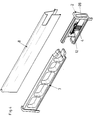
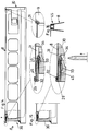
- die Fig. 4
- ein Schaubild einer einzelnen Schubladenzarge und zweier Teilstücke,
- die Fig. 5
- ein Schaubild einer Schubladenzarge mit abgenommener Außenwand,
- die Fig. 6
- schematisch einen Querschnitt der Schubladenzarge gemäß Fig. 5,
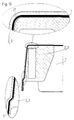
- die Fig. 7
- ein Schaubild zweier Teilstücke und einer Befestigungseinrichtung für eine Frontblende,
- die Fig. 8
- eine Seitenansicht eines Profilteiles,
- die Fig. 9 und 10
- je einen Querschnitt durch eine Schubladenzarge und ein hinteres Teilstück,
- die Fig. 11 und 12
- jeweils eine Seitenansicht des Kupplungsbereiches der Teilstücke,
- die Fig. 13
- einen Querschnitt durch die Teilstücke im Bereich der Abdeckplatten,
- die Fig. 14
- eine Seitenansicht eines weiteren Ausführungsbeispieles einer erfindungsgemäßen Schublade teilweise im Schnitt,
- die Fig. 15
- eine Seitenansicht des hinteren Endes einer erfindungsgemäßen Schublade teilweise im Schnitt,
- die Fig. 16
- eine schematische Stirnansicht des hinteres Endes der Schubladenzarge,
- die Fig. 17 und 18
- analoge Ansichten zu den Fig. 14 und 15 bei einer Schublade gemäß einem weiteren Ausführungsbeispiel der Erfindung und
- die Fig. 19
- einen Querschnitt durch eine Schubladenzarge und den Profilteil gemäß dem Ausführungsbeispiel nach den Fig. 17 und 18.
Claims (16)
- Schublade mit zwei doppelwandigen Schubladenzargen, in denen Profilteile aus einem Kunststoffmaterial aufgenommen sind, die sich über die ganze Länge der Schubladenzargen erstrecken, dadurch gekennzeichnet, daß die Profilteile vordere Abdeckplatten (19) aufweisen, die an den Stirnseiten der Schubladenzargen (8) anliegen und daß an den hinteren Enden der Profilteile Halteelemente vorgesehen sind, die auf die Schubladenzargen (8) aufgeschoben und in den Profilteilen verankert sind.
- Schublade nach Anspruch 1, dadurch gekennzeichnet, daß die Profilteile aus separaten vorderen und hinteren Teilstücken (2, 3) bestehen, die die vorderen und hintere Abdeckplatten (19, 20) aufweisen, mit denen sie an den vorderen und hinteren Stirnseiten der Schubladenzargen (8) anliegen, und die mittels Haken (9, 10, 13, 14) od. dgl. miteinander kuppelbar sind.
- Schublade nach Anspruch 1 oder 2, dadurch gekennzeichnet, daß beide Abdeckplatten (19, 20) Nuten (21) aufweisen, in denen die Enden der Schubladenzargen (8) aufgenommen sind.
- Schublade nach einem der Ansprüche 1 bis 3, dadurch gekennzeichnet, daß in den vorderen Teilstücken (2) Verankerungsmittel (12) für die Halterungen (11) einer Frontblende vorgesehen sind, die durch stirnseitige Öffnungen in die Teilstücke (2) einsteckbar sind.
- Schublade nach Anspruch 2, dadurch gekennzeichnet, daß die hinteren Teilstücke (3) mit einer oben offenen Hohlkammer (5) zur Aufnahme von Haltestiften (28) einer Rückwanderhöhung (6) ausgebildet sind.
- Schublade nach Anspruch 2, dadurch gekennzeichnet, daß zumindestens ein Teil der Haken (9, 10, 13, 14) federn ausgebildet ist.
- Schubladen nach einem der Ansprüche 2 bis 6, dadurch gekennzeichnet, daß jedes Teilstück (2, 3) zwei übereinander angeordnete Haken (9, 10, 13, 14) aufweist, die nach entgegengesetzten Richtungen weisen.
- Schublade nach einem der Ansprüche 2 bis 7, dadurch gekennzeichnet, daß die hinteren Teilstücke (3) mit in einer vertikalen Ebene verschieb- oder verschwenkbaren Halteteilen versehen sind, die jeweils in einer Bördelung (23) der Außenwand (8'') der Schubladenzargen (8) einrasten.
- Schublade nach Anspruch 8, dadurch gekennzeichnet, daß die Halteteile von Schiebern (16) oder schwenkbaren Heben (15) gebildet werden, die schräge Anschlußflächen (24, 24') für Haken (13) oder vorderen Teilstücke (2) aufweisen.
- Schublade nach einem der Ansprüche 1 und 3 bis 9, dadurch gekennzeichnet, daß die Halteelemente von vorzugsweise keilförmigen Schiebern (45) gebildet werden, die zwischen die Profilteile (30) und die Schubladenzargen (8) eingeschoben sind.
- Schublade nach Anspruch 10, dadurch gekennzeichnet, daß die Schieber (45) am Scheitel der Schubladenzargen (8) und der Profilteile (30) angeordnet sind.
- Schublade nach Anspruch 10 oder 11, dadurch gekennzeichnet, daß die Schieber (45) je einen Haken (27) aufweisen, der in einer Öffnung (34) oder hinter einem Vorsprung des Profilteiles (30) einrastet.
- Schublade nach einem der Ansprüche 10 bis 12, dadurch gekennzeichnet, daß der Schieber (45) die äußere obere Ecke der Schubladenzarge (8) abdeckt.
- Schublade nach einem der Ansprüche 1 und 3 bis 9, dadurch gekennzeichnet, daß die Halteelemente von an den Profilteilen (30) drehbar gelagerten Kipphebeln (35) gebildet werden.
- Schublade nach Anspruch 14, dadurch gekennzeichnet, daß jeder Kipphebel (35) einen am Profilteil (30) angelenkten Arm (37) aufweist, der in der Verankerungsstellung an der hinteren Stirnseite der Schubladenzarge (8) anstößt und einen von diesem Arm (37) abstehenden Arm (39), an dem ein Haken (40) ausgebildet ist, der in einer Öffnung oder hinter einem Vorsprung (41) des Profilteiles (30) einrastet.
- Schublade nach Anspruch 15, dadurch gekennzeichnet, daß der am Profilteil (30) angelenkte Arm (37) bei seinem freien Ende einen Schlitz (38) aufweist, in den der hintere Rand der Schubladenzarge (8) eingeschoben ist.
Applications Claiming Priority (3)
| Application Number | Priority Date | Filing Date | Title |
|---|---|---|---|
| AT494/97 | 1997-03-21 | ||
| AT0049497A AT407332B (de) | 1997-03-21 | 1997-03-21 | Schublade |
| AT49497 | 1997-03-21 |
Publications (4)
| Publication Number | Publication Date |
|---|---|
| EP0865745A2 true EP0865745A2 (de) | 1998-09-23 |
| EP0865745A3 EP0865745A3 (de) | 2001-09-26 |
| EP0865745B1 EP0865745B1 (de) | 2004-03-03 |
| EP0865745B9 EP0865745B9 (de) | 2004-10-06 |
Family
ID=3492101
Family Applications (1)
| Application Number | Title | Priority Date | Filing Date |
|---|---|---|---|
| EP98104530A Expired - Lifetime EP0865745B9 (de) | 1997-03-21 | 1998-03-13 | Schublade |
Country Status (6)
| Country | Link |
|---|---|
| US (1) | US6053593A (de) |
| EP (1) | EP0865745B9 (de) |
| JP (1) | JP4296553B2 (de) |
| AT (2) | AT407332B (de) |
| DE (1) | DE59810864D1 (de) |
| ES (1) | ES2217448T3 (de) |
Cited By (6)
| Publication number | Priority date | Publication date | Assignee | Title |
|---|---|---|---|---|
| WO2012169982A1 (en) * | 2011-06-09 | 2012-12-13 | SAMET KALIP VE MADENI EŞYA SANAYI VE TICARET ANONI'M Şl'RKETI | Locking mechanism for a drawer front panel |
| WO2013025181A3 (en) * | 2011-08-16 | 2013-06-13 | SAMET KALIP VE MADENI ESYA SANAYI VE TICARET ΑΝΟΝΪΜ SJRKETi | Locking mechanism for a drawer front panel |
| AT13225U1 (de) * | 2011-05-20 | 2013-08-15 | Blum Gmbh Julius | Doppelwandige Schubladenzarge |
| EP3275339A1 (de) * | 2016-07-26 | 2018-01-31 | Plastimodul, S.L. | Teil und frontverschlusseinheit zur montage von schubladen |
| WO2018095820A1 (de) * | 2016-11-25 | 2018-05-31 | Paul Hettich Gmbh & Co. Kg | Schubkasten |
| WO2020233966A1 (de) * | 2019-05-17 | 2020-11-26 | Paul Hettich Gmbh & Co. Kg | Seitenzarge für einen schubkasten |
Families Citing this family (13)
| Publication number | Priority date | Publication date | Assignee | Title |
|---|---|---|---|---|
| TW200509836A (en) * | 2003-04-23 | 2005-03-16 | Brush & Co John D | Stackable blow molded cabinet |
| ATE463973T1 (de) * | 2006-12-15 | 2010-04-15 | Harn Marketing Sdn Bhd | Eckbeschlag |
| AT510774B1 (de) * | 2010-11-23 | 2014-12-15 | Blum Gmbh Julius | Befestigungsvorrichtung für wandteile |
| ITMI20111628A1 (it) * | 2011-09-08 | 2013-03-09 | Salice Arturo Spa | Dispositivo e metodo per il centraggio laterale di un cassetto o simile su una guida di estrazione e dispositivo di aggancio provvisto dello stesso |
| USD672168S1 (en) * | 2011-12-20 | 2012-12-11 | Tait Towers Inc. | Display module frame |
| USD670936S1 (en) * | 2011-12-20 | 2012-11-20 | Tait Towers Inc. | Display module frame |
| DE202013011425U1 (de) | 2013-12-20 | 2015-03-23 | Grass Gmbh | Schubladenwandelement und Füllelement für eine Schubladenwand sowie Möbel |
| DE202013011421U1 (de) * | 2013-12-20 | 2015-03-23 | Grass Gmbh | Schubladenfrontanbindungselnheit |
| CN108433407A (zh) * | 2017-02-16 | 2018-08-24 | 苏树鹏 | 抽屉面板调整装置 |
| AT520765B1 (de) * | 2017-12-21 | 2023-03-15 | Blum Gmbh Julius | Schubladenseitenwand mit einem Abdeckprofil |
| AT520803B1 (de) * | 2017-12-22 | 2023-05-15 | Blum Gmbh Julius | Schubladenseitenwand |
| AT525777B1 (de) * | 2021-12-21 | 2025-06-15 | Blum Gmbh Julius | Doppelwandige Schubladenzarge |
| TWI843468B (zh) * | 2023-03-06 | 2024-05-21 | 川湖科技股份有限公司 | 傢俱及其傢俱組件 |
Citations (1)
| Publication number | Priority date | Publication date | Assignee | Title |
|---|---|---|---|---|
| AT355756B (de) | 1977-02-25 | 1980-03-25 | Duepree Hans Werner | Schublade aus kunststoff |
Family Cites Families (13)
| Publication number | Priority date | Publication date | Assignee | Title |
|---|---|---|---|---|
| AT382071B (de) * | 1977-05-13 | 1987-01-12 | Blum Gmbh Julius | Schubladenfuehrung |
| EP0030290B1 (de) * | 1979-11-20 | 1984-03-21 | Ninkaplast GmbH | Schublade |
| DE3044471C2 (de) * | 1980-11-26 | 1986-10-30 | Düpree, Hans-Werner, 4830 Gütersloh | Schublade aus Kunststoff |
| DE3537335A1 (de) * | 1985-10-19 | 1987-04-23 | Leicht Einbaukuechen Gmbh | Schubkasten od. dgl. schrankauszug |
| DE3601679A1 (de) * | 1986-01-21 | 1987-07-23 | Grass Alfred Metallwaren | Schublade mit fuehrungsprofil |
| DE3609621A1 (de) * | 1986-03-21 | 1987-09-24 | Bbp Kunststoffwerk | Schubkasten fuer moebel |
| AT398514B (de) * | 1990-07-12 | 1994-12-27 | Alfit Ag | Schublade mit metallischen zargen |
| DE4200581C1 (de) * | 1992-01-11 | 1993-07-29 | Mepla-Werke Lautenschlaeger Gmbh & Co Kg, 6107 Reinheim, De | |
| DE4330919A1 (de) * | 1993-09-11 | 1995-03-16 | Lautenschlaeger Mepla Werke | Eck-Verbindungsbeschlag für Schubladen |
| ES2124437T3 (es) * | 1994-01-17 | 1999-02-01 | Blum Gmbh Julius | Cajon. |
| ES2121485B1 (es) * | 1994-03-30 | 1999-05-16 | Calvo Miguel Angel Rioja | Perfeccionamientos en la constitucion de cajones de muebles. |
| AT402596B (de) * | 1994-08-26 | 1997-06-25 | Blum Gmbh Julius | Möbelbeschlag, insbesondere verbindungsbeschlag möbelbeschlag, insbesondere verbindungsbeschlag |
| DE4433577A1 (de) * | 1994-09-21 | 1996-03-28 | Hettich Paul Gmbh & Co | Möbelauszugsteil |
-
1997
- 1997-03-21 AT AT0049497A patent/AT407332B/de not_active IP Right Cessation
-
1998
- 1998-03-13 EP EP98104530A patent/EP0865745B9/de not_active Expired - Lifetime
- 1998-03-13 ES ES98104530T patent/ES2217448T3/es not_active Expired - Lifetime
- 1998-03-13 DE DE59810864T patent/DE59810864D1/de not_active Expired - Lifetime
- 1998-03-13 AT AT98104530T patent/ATE260587T1/de not_active IP Right Cessation
- 1998-03-19 JP JP07044198A patent/JP4296553B2/ja not_active Expired - Fee Related
- 1998-03-20 US US09/045,368 patent/US6053593A/en not_active Expired - Fee Related
Patent Citations (1)
| Publication number | Priority date | Publication date | Assignee | Title |
|---|---|---|---|---|
| AT355756B (de) | 1977-02-25 | 1980-03-25 | Duepree Hans Werner | Schublade aus kunststoff |
Cited By (10)
| Publication number | Priority date | Publication date | Assignee | Title |
|---|---|---|---|---|
| AT13225U1 (de) * | 2011-05-20 | 2013-08-15 | Blum Gmbh Julius | Doppelwandige Schubladenzarge |
| WO2012169982A1 (en) * | 2011-06-09 | 2012-12-13 | SAMET KALIP VE MADENI EŞYA SANAYI VE TICARET ANONI'M Şl'RKETI | Locking mechanism for a drawer front panel |
| WO2013025181A3 (en) * | 2011-08-16 | 2013-06-13 | SAMET KALIP VE MADENI ESYA SANAYI VE TICARET ΑΝΟΝΪΜ SJRKETi | Locking mechanism for a drawer front panel |
| EP3275339A1 (de) * | 2016-07-26 | 2018-01-31 | Plastimodul, S.L. | Teil und frontverschlusseinheit zur montage von schubladen |
| WO2018095820A1 (de) * | 2016-11-25 | 2018-05-31 | Paul Hettich Gmbh & Co. Kg | Schubkasten |
| KR20190088968A (ko) * | 2016-11-25 | 2019-07-29 | 파울 헤티히 게엠베하 운트 콤파니 카게 | 서랍 |
| US10729242B2 (en) | 2016-11-25 | 2020-08-04 | Paul Hettich Gmbh & Co. Kg | Drawer |
| WO2020233966A1 (de) * | 2019-05-17 | 2020-11-26 | Paul Hettich Gmbh & Co. Kg | Seitenzarge für einen schubkasten |
| CN113645880A (zh) * | 2019-05-17 | 2021-11-12 | 保罗海蒂诗有限及两合公司 | 用于抽屉的侧面板 |
| CN113645880B (zh) * | 2019-05-17 | 2023-07-25 | 保罗海蒂诗有限及两合公司 | 用于抽屉的侧面板 |
Also Published As
| Publication number | Publication date |
|---|---|
| ATA49497A (de) | 2000-07-15 |
| DE59810864D1 (de) | 2004-04-08 |
| EP0865745B1 (de) | 2004-03-03 |
| AT407332B (de) | 2001-02-26 |
| EP0865745A3 (de) | 2001-09-26 |
| EP0865745B9 (de) | 2004-10-06 |
| ES2217448T3 (es) | 2004-11-01 |
| ATE260587T1 (de) | 2004-03-15 |
| US6053593A (en) | 2000-04-25 |
| JP4296553B2 (ja) | 2009-07-15 |
| JPH10262758A (ja) | 1998-10-06 |
Similar Documents
| Publication | Publication Date | Title |
|---|---|---|
| EP0865745A2 (de) | Schublade | |
| EP1084655B1 (de) | Befestigungsanordnung | |
| EP0706012B1 (de) | Gargerät | |
| DE29902174U1 (de) | Auszug mit Relingaufsatz | |
| EP0743035B1 (de) | Stuhl, insbesondere Bürostuhl, mit einer höhenverstellbaren Rückenlehnenkonstruktion | |
| DE19511639C1 (de) | Schaltschrank mit Rahmengestell und Montageplatte | |
| EP1157636A1 (de) | Befestigungsanordnung | |
| EP0096898B1 (de) | Auszug für Schränke | |
| DE69907078T2 (de) | Beleuchtetes Regal | |
| DE2113398A1 (de) | In Form eines Tisches ausgebildetes Moebelstueck | |
| DE19738505C1 (de) | Tür für ein Haushaltsgerät, insbesondere einen Haushaltsgarofen | |
| AT5171U1 (de) | Doppelwandige aufsatzzarge | |
| EP3852579B1 (de) | Schubkasten und einheit aus einer auszugsführung und einem schubkasten | |
| EP1084656A1 (de) | Befestigungsanordnung | |
| DE3119606C2 (de) | Ausziehtisch | |
| EP0774627B1 (de) | Standherd mit Schubkasten | |
| EP0653598A1 (de) | Kühlschrank | |
| EP1228719B1 (de) | Schubkasten mit lösbarer Frontblende | |
| AT522739A2 (de) | Innenschubkasten und Möbel oder Haushaltsgerät | |
| DE3703249C2 (de) | Halte- und Auszieheinrichtung | |
| DE3221926C2 (de) | Auszieheinrichtung für einen mit einem Möbelkorpus versehenen Schrank | |
| DE3445234C2 (de) | ||
| AT398515B (de) | Beschlag zur lösbaren halterung | |
| DE29518606U1 (de) | Abfallsammeleinrichtung | |
| DE2646282A1 (de) | Ausziehbeschlag |
Legal Events
| Date | Code | Title | Description |
|---|---|---|---|
| PUAI | Public reference made under article 153(3) epc to a published international application that has entered the european phase |
Free format text: ORIGINAL CODE: 0009012 |
|
| AK | Designated contracting states |
Kind code of ref document: A2 Designated state(s): AT BE CH DE DK ES FI FR GB GR IE IT LI LU MC NL PT SE Kind code of ref document: A2 Designated state(s): AT DE ES IT |
|
| AX | Request for extension of the european patent |
Free format text: AL;LT;LV;MK;RO;SI |
|
| PUAL | Search report despatched |
Free format text: ORIGINAL CODE: 0009013 |
|
| AK | Designated contracting states |
Kind code of ref document: A3 Designated state(s): AT BE CH DE DK ES FI FR GB GR IE IT LI LU MC NL PT SE |
|
| AX | Request for extension of the european patent |
Free format text: AL;LT;LV;MK;RO;SI |
|
| RIC1 | Information provided on ipc code assigned before grant |
Free format text: 7A 47B 88/00 A, 7A 47B 88/04 B |
|
| 17P | Request for examination filed |
Effective date: 20020311 |
|
| AKX | Designation fees paid |
Free format text: AT DE ES IT |
|
| 17Q | First examination report despatched |
Effective date: 20021219 |
|
| GRAP | Despatch of communication of intention to grant a patent |
Free format text: ORIGINAL CODE: EPIDOSNIGR1 |
|
| GRAS | Grant fee paid |
Free format text: ORIGINAL CODE: EPIDOSNIGR3 |
|
| GRAA | (expected) grant |
Free format text: ORIGINAL CODE: 0009210 |
|
| AK | Designated contracting states |
Kind code of ref document: B1 Designated state(s): AT DE ES IT |
|
| PG25 | Lapsed in a contracting state [announced via postgrant information from national office to epo] |
Ref country code: AT Free format text: LAPSE BECAUSE OF NON-PAYMENT OF DUE FEES Effective date: 20040313 |
|
| REF | Corresponds to: |
Ref document number: 59810864 Country of ref document: DE Date of ref document: 20040408 Kind code of ref document: P |
|
| RAP2 | Party data changed (patent owner data changed or rights of a patent transferred) |
Owner name: JULIUS BLUM GESELLSCHAFT M.B.H. |
|
| REG | Reference to a national code |
Ref country code: ES Ref legal event code: FG2A Ref document number: 2217448 Country of ref document: ES Kind code of ref document: T3 |
|
| PLBE | No opposition filed within time limit |
Free format text: ORIGINAL CODE: 0009261 |
|
| STAA | Information on the status of an ep patent application or granted ep patent |
Free format text: STATUS: NO OPPOSITION FILED WITHIN TIME LIMIT |
|
| 26N | No opposition filed |
Effective date: 20041206 |
|
| PGFP | Annual fee paid to national office [announced via postgrant information from national office to epo] |
Ref country code: IT Payment date: 20110326 Year of fee payment: 14 |
|
| PGFP | Annual fee paid to national office [announced via postgrant information from national office to epo] |
Ref country code: ES Payment date: 20110322 Year of fee payment: 14 |
|
| PGFP | Annual fee paid to national office [announced via postgrant information from national office to epo] |
Ref country code: DE Payment date: 20120526 Year of fee payment: 15 |
|
| PG25 | Lapsed in a contracting state [announced via postgrant information from national office to epo] |
Ref country code: IT Free format text: LAPSE BECAUSE OF NON-PAYMENT OF DUE FEES Effective date: 20120313 |
|
| REG | Reference to a national code |
Ref country code: ES Ref legal event code: FD2A Effective date: 20130711 |
|
| PG25 | Lapsed in a contracting state [announced via postgrant information from national office to epo] |
Ref country code: ES Free format text: LAPSE BECAUSE OF NON-PAYMENT OF DUE FEES Effective date: 20120314 |
|
| REG | Reference to a national code |
Ref country code: DE Ref legal event code: R119 Ref document number: 59810864 Country of ref document: DE Effective date: 20131001 |
|
| PG25 | Lapsed in a contracting state [announced via postgrant information from national office to epo] |
Ref country code: DE Free format text: LAPSE BECAUSE OF NON-PAYMENT OF DUE FEES Effective date: 20131001 |