EP0864365A1 - Mehrwalzenbrecher - Google Patents
Mehrwalzenbrecher Download PDFInfo
- Publication number
- EP0864365A1 EP0864365A1 EP97305921A EP97305921A EP0864365A1 EP 0864365 A1 EP0864365 A1 EP 0864365A1 EP 97305921 A EP97305921 A EP 97305921A EP 97305921 A EP97305921 A EP 97305921A EP 0864365 A1 EP0864365 A1 EP 0864365A1
- Authority
- EP
- European Patent Office
- Prior art keywords
- role
- crushing
- roles
- teeth
- crusher
- Prior art date
- Legal status (The legal status is an assumption and is not a legal conclusion. Google has not performed a legal analysis and makes no representation as to the accuracy of the status listed.)
- Granted
Links
Images


Classifications
-
- B—PERFORMING OPERATIONS; TRANSPORTING
- B02—CRUSHING, PULVERISING, OR DISINTEGRATING; PREPARATORY TREATMENT OF GRAIN FOR MILLING
- B02C—CRUSHING, PULVERISING, OR DISINTEGRATING IN GENERAL; MILLING GRAIN
- B02C13/00—Disintegrating by mills having rotary beater elements ; Hammer mills
- B02C13/20—Disintegrating by mills having rotary beater elements ; Hammer mills with two or more co-operating rotors
-
- B—PERFORMING OPERATIONS; TRANSPORTING
- B02—CRUSHING, PULVERISING, OR DISINTEGRATING; PREPARATORY TREATMENT OF GRAIN FOR MILLING
- B02C—CRUSHING, PULVERISING, OR DISINTEGRATING IN GENERAL; MILLING GRAIN
- B02C4/00—Crushing or disintegrating by roller mills
- B02C4/02—Crushing or disintegrating by roller mills with two or more rollers
- B02C4/08—Crushing or disintegrating by roller mills with two or more rollers with co-operating corrugated or toothed crushing-rollers
Definitions
- the present invention relates to a multiaxes role type of crusher, and in particular relates to a multiaxes role type of crusher for efficiently crushing hard raw materials such as stone or concrete.
- 2-axes role types of crushers for crushing raw stones are known.
- One 2-axes role type of crusher has one pair of roles. The roles have the respective teeth on the respective cylindrical surfaces thereof. Stones are crushed between the teeth of the role on the one side and the teeth on the other side, both sets of teeth being continually oncoming during the rotation.
- An object of the present invention is to provide a multiaxes role type of crusher which has a high crushing efficiency.
- Another object of the present invention is to provide a multiaxes role type of crusher which can crush twice the conventional amount of raw materials per unit time.
- a further object of the present invention is to provide a multiaxes role type of crusher which can crush more than twice the conventional amount of raw materials per unit time.
- a still further object of the present invention is to provide a multiaxes role type of crusher which has a high crushing efficiency, and facilitates discharging heterogeneous materials.
- a multiaxes role type of crusher comprises four roles. Each of the four roles respectively has teeth for directly crushing materials. Materials are introduced or inserted between a pairs of roles. There would be virtually 6 pairs of roles mathematically. One pair of roles includes two roles. At least 3 pairs are actually used by the crusher. That is, there are 3 crushing-relations given. The respective pairs correspond to the respective relations where materials can be crushed. Such relations are called crushing-relations in the specification. There are at least 3 crushing-relations given for a crusher according to the present invention.
- the first crushing-relation is the relation of the first role to the second role.
- the second crushing-relation is the relation of the first role to the third role.
- the third crushing-relation is the relation of the second role to the fourth role.
- Raw materials such as stones, concrete, asphalt and so on are crushed to a smaller size in diameter with the first crushing-relation. That is, raw materials are crushed between the first role and the second role.
- the crushed materials crushed in the first crushing-relation which are named the first crushed materials, are secondly crushed in the second crushing-relation or the third crushing-relation between the first role and the third role or between the second role and the fourth role.
- the secondly crushed materials which are named the second crushed materials, are still smaller in size of diameter than the first crushed materials.
- the first crushing-relation has the first role rotating in the counterclockwise direction, while the second role rotates in the clockwise direction.
- the second crushing-relation has the first role rotating in the counterclockwise direction, while the third role rotates in the clockwise direction.
- the third crushing-relation is in that the second role rotates in the clockwise direction, while the fourth role rotates in the counterclockwise direction.
- the first role and the second role rotate in opposite directions and in reversely opposite directions.
- the third role and the fourth role rotate in opposite directions and in reversely opposite directions.
- the second role is located relative to the first role so that raw materials are crushed between the first role and the second role.
- the third role is located relative to the first role so that the first crushed materials are crushed between the first role and the third role.
- the fourth role is located relative to the second role so that the first crushed materials are crushed between the second role and the fourth role.
- Such locations are defined as follows.
- the cylindrical surface which includes the locus of rotation of the outer end of the first crushing teeth does not overlap with the cylindrical surface including the locus of rotation of the outer end of the second crushing teeth, while the cylindrical surface including the locus of rotation of the outer end of the first crushing teeth overlaps with the cylindrical surface including the locus of rotation of the outer end of the third crushing teeth, and the cylindrical surface including the locus of rotation of the outer end of the second crushing teeth overlaps with the cylindrical surface including the locus of rotation of the outer end of the fourth crushing teeth.
- One pair of roles may simultaneously rotate in the respective reverse directions.
- Another pair of roles may simultaneously rotate in the respective reverse directions.
- the further pair of roles, those of the second role and the fourth role may simultaneously rotate in the respective reverse directions. It is desirable that one role may rotate in the clockwise direction and in the counterclockwise direction independently of the other roles.
- a multiaxes role type of crusher further comprises a controlling means.
- the controlling means may be located among the four roles or may be located between the third role and the fourth role. It is desirable that the controlling means is located under the plane including the center line of the rotating axis of the third role and the center line of the rotating axis of the fourth role.
- the controlling means is movable in the upward direction and an the downward direction.
- the fluid of the second crushed materials are restricted by the controlling means, which moves in the upward direction and is at rest in the bottom position. Under the condition of restriction, the first crushed materials are secondly and effectively crushed.
- the controlling means at the top position facilitates the flow of the first crushed materials so that they are led between the first role and the third role, and led between the second role and the fourth role. With heterogeneous or alloyed materials such as iron, the controlling means retracts in the downward direction. Under the condition of retraction, the first crushing-relation, the second crushing-relation and the third crushing-relation are simultaneously cancelled.
- Fig. 1 is a front view showing a first embodiment of a multiaxes role type of crusher according to the present invention.
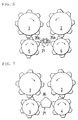
- Fig. 2 is a front view showing another position of rotation of the roles of the embodiment.
- Fig. 3 is a front view showing a further different position of rotation of the roles of the embodiment.
- Fig. 4 is a front view showing another state of operation of the embodiment.
- Fig. 5 is a front view showing an improved fluid controlling body.
- Fig. 6 is a front view showing a further improved fluid controlling body.
- Fig. 7 is a front view showing a further improved fluid controlling body.
- Fig. 8 is a front view showing a further improved fluid controlling body.
- Fig. 9 is a front view showing a driving system for driving the roles of Fig. 1.
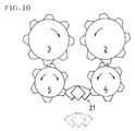
- Fig. 10 is a front view showing a further improved fluid controlling body.
- Fig. 11 is a front sectional view showing one condition of crushing according to the embodiment of Fig. 1.
- Fig. 12 is a front sectional view showing another condition of crushing according to the embodiment of Fig. 1.
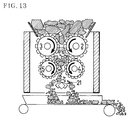
- Fig. 13 is a front sectional view showing a further condition of crushing according to the embodiment of Fig. 1.
- Fig. 1 illustrates an embodiment of a multiaxes role type of crusher according to the present invention.
- the crusher comprises four roles.
- the first crushing teeth 7 are provided with a first role 2.
- the first rotating center line J1 of the rotating axis of first role 2 is abstractly denoted by a point.
- the second crushing teeth 9 are provided with a second role 3.
- the second rotating center line J2 of the rotating axis of second role 3 is abstractly denoted by a point.
- the third crushing teeth 12 are provided with a third role 4.
- the third rotating center line J3 of the rotating axis of third role 4 is abstractly denoted by a point.
- the fourth crushing teeth 14 are provided with a fourth role 5.
- the fourth rotating center line J4 of the rotating axis of fourth role 5 is abstractly denoted by a point.
- the first, second, third and fourth rotating center lines J1,J2,J3 and J4 are substantially or generally parallel with one another.
- the first and second rotating center lines J1,J2 are desirably contained on one horizontal plane.
- the third and fourth rotating center lines are desirably included in another horizontal plane.
- First role 2 comprises a first rotating drum 6.
- First crushing teeth 7 are fixed with first rotating drum 6.
- First crushing teeth 7 respectively protrude from the cylindrical surface of first rotating drum 6 in the radial direction.
- a first quartet of teeth are positioned at the equal intervals in the circumferential direction.
- Second role 3 comprises a second rotating drum 8.
- Second crushing teeth 9 are fixed with second rotating drum 8.
- Second crushing teeth 9 respectively protrude from the cylindrical surface of second rotating drum 8 in the radial direction.
- a second quartet of second crushing teeth 9 are positioned at equal intervals in the circumferential direction.
- Third role 4 comprises a third rotating drum 11.
- Third crushing teeth 12 are fixed with third rotating drum 11.
- Third crushing teeth 12 respectively protrude from the cylindrical surface of third rotating drum 11 in the radial direction.
- a third quartet of teeth are positioned at the equal intervals in the circumferential direction.
- Fourth role 5 comprises a fourth rotating drum 13.
- Fourth crushing teeth 14 are fixed with fourth rotating drum 13.
- Fourth crushing teeth 14 respectively protrude from the cylindrical surface of fourth rotating drum 13 in the radial direction.
- a fourth quartet of teeth are positioned at equal intervals in the circumferential direction.
- the respective sets of teeth are positioned on the respective surfaces of the respective drums, and line up in the respective axial directions.
- the second set of second crushing teeth 9 lining in the axial direction have the respective differences of 180 degrees in phases with respect to the first set of first crushing teeth 7 lining in the axial direction.
- the third set of third crushing teeth 12 lining in the axial direction have respective differences of 180 degrees in phases with respect to the first set of first crushing teeth 7 lining in the axial direction.
- the fourth set of fourth crushing teeth 14 lining in the axial direction have respective differences of 180 degrees in phases with respect to the third set of second crushing teeth 9 lining in the axial direction.
- the four roles may not be equal in size.
- the position of first rotating center line J1 is equal in height to the position of second rotating center line J2.
- the position of third rotating center line J3 is equal in height to the position of fourth rotating center line J4.
- the position of first rotating center line J1 is higher than the position of fourth rotating center line J4.
- the distance between first rotating center line J1 and second rotating center line J2 is longer than the distance between third rotating center line J3 and fourth rotating center line J4.
- first crushing-relation between first role 2 and second role 3 in that first role 2 rotates in the counterclockwise direction while second role 3 rotates in the clockwise direction.
- second crushing-relation between first role 2 and third role 4 in that first role 2 rotates in the counterclockwise direction while third role 4 rotates in the clockwise direction.
- third crushing-relation between second role 3 and fourth role 5 in that second role 3 rotates in the clockwise direction, while fourth role 5 rotates in the counterclockwise direction.
- third crushing-relation between third role 4 and fourth role 5 in that third role 2 rotates in the clockwise direction, while fourth role 5 rotates in the counterclockwise direction.
- third crushing-relation between third role 4 and fourth role 5 in that third role 2 rotates in the clockwise direction, while fourth role 5 rotates in the counterclockwise direction.
- the first cylindrical surface including the locus of rotation of the outer end of first crushing teeth 7 does not overlap with the second cylindrical surface including the locus of rotation of the outer end of second crushing teeth 9.
- the first cylindrical surface including the locus of rotation of the outer end of first crushing teeth 7 overlaps with the third cylindrical surface including the locus of rotation of the outer end of third crushing teeth 12.
- the cylindrical surface including the locus of rotation of the outer end of second crushing teeth 9 overlaps with the fourth cylindrical surface including the locus of rotation of the outer end of fourth crushing teeth 14.
- Raw materials are crushed in the first crushing-relation to be made of smaller size.
- the first crushed materials crushed between first role 2 and second role 3 are secondly crushed in the second crushing-relation between first role 2 and third role 4 to be made yet smaller in size than the first crushed materials.
- the first crushed materials are secondly crushed in the third crushing-relation between second role 3 and fourth role 5 to be made still smaller in size than the first crushed materials. It is possible that one more crushing-relation is given between third role 4 and fourth role 5.
- Fig. 2 illustrates one state in that the respective roles 2,3,4,5 advance in the respective phases of 30 degrees with respect to the roles shown in Fig. 1.
- Fig. 3 illustrates another state in that the respective roles 2,3,4,5 further advance in the respective phases of 30 degrees with respect to the roles shown in Fig. 2.
- Figs. 1,2,3, the four roles synchronously rotate.
- Fig. 1 illustrates a fluid controlling means 21 for controlling the fluid produced between the four roles.
- the fluid controlling means 21 includes a supporting axis 22 and a pair of wings 23. Wings 23 are supported by supporting axis 22. Pair of wings 23 opens or closes the fluid passage formed between third role 4 and fourth role 5.
- the first fluid of the first crushed materials is not restricted by opened fluid controlling means 21.
- the first fluid from the space between first role 2 and second role 3 towards the space between third role 4 and fourth role 5 is restricted by closed fluid controlling means 21.
- fluid controlling means 21 facilitates the second fluid from the space between first role 2 and second role 3 towards the space between first role 2 and third role 4, and fluid controlling means 21 facilitates the third fluid from the space between first role 2 and second role 3 towards the space between second role 3 and fourth role 5.
- Fig. 4 illustrates a method for controlling fluids.
- First role 2 rotates in the counterclockwise direction, while second role 3 rotates in the clockwise direction. There is a crushing-relation between first role 2 and second role 3.
- Third role 4 rotates in the counterclockwise direction, while fourth role 5 rotates in the clockwise direction. There is no crushing-relation between first role 2 and third role 4, and there is no crushing-relation between second role 3 and fourth role 5. That is, the second and third crushing-relations are cancelled by the reverse of the respective rotations of the third role and the fourth role.
- fluid controlling means 21 facilitates the first fluid from the space between first role 2 and second role 3 towards the space between third role 4 and fourth role 5.
- the above mentioned overlappings of two pairs of roles facilitate making the second crushed materials smaller in size than the first crushed materials.
- the shorter the distance between a pair of roles the smaller the materials are crushed in size.
- the shorter the distance between a pair of drums of a pair of roles the smaller the materials are crushed in size.
- the quantity of materials to be crushed by a 4-axes crusher according to the present invention is defined by twice the quantity of materials to be crushed between first role 2 and third role 4. This means that a crusher according to the present invention corresponds in crushing capacity to the three 2-axes crushers of the conventional type.
- Fig . 5 illustrates a second embodiment of a 4-axes role type of crusher according to the present invention.
- This embodiment is not different from the first embodiment in respect to the fact that a second crusher according to the second embodiment comprises 4 roles, and there are three crushing-relations given thereto.
- the first, second, third and fourth rotating center lines J1,J2,J3,J4 pass four apexes of a rectangle.
- the distance between first rotating center line J1 and second rotating center line J2 is equal to the distance between third rotating center line J3 and fourth rotating center line J4.
- the distance between first rotating center line J1 and third rotating center line J3 is equal to the distance between second rotating center line J2 and fourth rotating center line J4.
- first rotating center line J1 and second rotating center line J2 is longer than the distance between first rotating center line J1 and third rotating center line J3.
- the diameter of the first cylindrical surface including the locus of rotation of the outer end of first crushing teeth 7 is equal to the diameter of the second cylindrical surface including the locus of rotation of the outer end of second crushing teeth 9, but the diameter of the first cylindrical surface including the locus of rotation of the outer end of first crushing teeth 7 is longer than the diameter of the third cylindrical surface including the locus of rotation of the outer end of third crushing teeth 12.
- Second role 3 is not different in size from first role 2.
- Fourth role 5 is not different in size from third role 4.
- Fourth role 5 is smaller in size than first role 2.
- Fig. 5 illustrates a revision of fluid controlling means 21.
- the revision comprises a pair of fluid controlling protrusions 21a and 21b positioned on one diameter line. Pair of fluid controlling protrusions 21a, 21b rotates by 90 degrees to open the path between third role 4 and fourth role 5 so that heterogeneous materials such as iron can pass through the path.
- the four roles are located on the inside of a casing 31.
- a products container 33 and a foreign materials container 32 are formed by casing 31.
- the second crushed materials between first role 2 and third role 4 or between second role 3 and fourth role 5 are led into products container 33 when fluid controlling means 21 is closed, and the foreign materials pass without obstruction by the pair of fluid controlling protrusions 21a,being led into foreign materials container 32 when fluid controlling means 21 is opened.
- Fig. 6 illustrates another revision of fluid controlling means 21.
- the fluid controlling means 21 comprises a pair of two rotatable plates 35a, 35b. Two rotatable plates respectively rotate by 45 degrees in opposite directions respectively.
- Fig. 7 illustrates a further revision of fluid controlling means 21.
- the fluid controlling means 21 comprises single rod 36, which is formed pentagonally in sectional form. Single rod 36 advances and retracts in the axial direction. Advancing single rod 36 appears into the space among the roles, while retracting rod 36 disappears from the space.
- Fig. 8 illustrates a further revision of fluid controlling means 21.
- the fluid controlling means 21 comprises single column 37.
- Single column 37 advances and retracts in the axial direction. Advancing single column 37 appears into the space among the roles, while retracting column 37 disappears from the space.
- Column 37 may be made of a pipe.
- Fig. 9 illustrates a further revision of fluid controlling means 21.
- the fluid controlling means 21 comprises single elevating pipe 51.
- Single elevating pipe 51 is located among the four roles.
- Single elevating pipe 51 is supported and driven by a driving cylinder 52.
- Single elevating pipe 51 moves in the upward direction and in the downward direction.
- Single elevating pipe 51a at the upper portion opens the path formed between third role 4 and fourth role 5, while single elevating pipe 51 at the lower portion closes the path formed between third role 4 and fourth role 5.
- Single elevating pipe 51a at the upper portion does not prevent the flow of foreign materials passing between third role 4 and fourth role 5.
- Both first role 2 and second role 3 are respectively(simultaneously) and reversely driven when the load of first role 2 and second role 3 is excessive. It is desirable that both third role 4 and fourth role 5 are respectively (simultaneously) and reversely driven when the load is excessive. Both first role 2 and third role 4 are respectively (simultaneously) and reversely driven when the load of first role 2 and third role 4 is excessive. It is desirable that both second role 3 and fourth role 5 are respectively (simultaneously) and reversely driven when the load is excessive. Such reverse rotation together with the driving of fluid controlling means 21 soon facilitates the cancellation of the obstruction of the flow(s).
- Fig. 10 illustrates an effective revision of fluid controlling means 21.
- This revision is not different from the above mentioned embodiments or revisions illustrated in Figs. 1,5,6,7,8,and 9.
- the three crushing-relations are not different from the above mentioned crushing-relations.
- this revision is not different from the above revisions in respect to the fact that the first flow is divided by fluid controlling means 21 into the second flow and the third flow. That is, fluid controlling means 21 of the above mentioned revisions is located on the inside of the space among the four roles.
- fluid controlling means 21 is located on the outside of the space among the four roles. Fluid controlling means 21 is located under the plane that includes third rotating center line J3 and fourth rotating center line J4. Fluid controlling means 21 moves in the upward direction and in the downward direction. Fluid controlling means 21 at the lower position perfectly opens the space between third role 4 and fourth role 5.
- FIG. 11 shows one condition of crushing where the crusher has the three crushing-relations, and the fluid between third role 4 and fourth role 5 is obstructed by fluid controlling means 21 at the upper position.
- the greater part of the second crushed materials pass through the path formed between second role 3 and fourth role 5 or the path formed between first role 2 and third role 4 to be discharged outside the respective spaces therebetween.
- the remaining part of the second crushed materials, which are smaller in size than the greater part pass through the narrower path formed between fluid controlling means 21 and third role 4 or between fluid controlling means 21 and fourth role 5.
- Fig. 12 shows another condition of crushing where the crusher substantially has no crushing-relation, and the fluid between third role 4 and fourth role 5 is not obstructed by fluid controlling means 21 at the lower position. Under this condition, the small quantity of the first crushed materials and the foreign materials are discharged through the path formed between third role 4 and fourth role 5. Materials such as iron are magnetically detected by a detector(not shown). Upon detecting fluid controlling means 21 moves in the downward direction.
- Fig. 13 shows the further condition of crushing where the first crushing-relation is not cancelled, but both second crushing-relation and third crushing-relation are cancelled.
- the first crushed materials are maintained in the size which they have when crushed between first role 2 and second role 3. Such crushed materials are discharged between third role 4 nd fourth role 5 without obstruction of fluid controlling means 21.
Landscapes
- Engineering & Computer Science (AREA)
- Food Science & Technology (AREA)
- Crushing And Grinding (AREA)
- Crushing And Pulverization Processes (AREA)
Applications Claiming Priority (6)
| Application Number | Priority Date | Filing Date | Title |
|---|---|---|---|
| JP7664697 | 1997-03-12 | ||
| JP76646/97 | 1997-03-12 | ||
| JP7664697 | 1997-03-12 | ||
| JP14476397 | 1997-05-19 | ||
| JP144763/97 | 1997-05-19 | ||
| JP14476397A JP3751712B2 (ja) | 1997-03-12 | 1997-05-19 | 多軸ロールクラッシャ |
Publications (2)
| Publication Number | Publication Date |
|---|---|
| EP0864365A1 true EP0864365A1 (de) | 1998-09-16 |
| EP0864365B1 EP0864365B1 (de) | 2002-11-13 |
Family
ID=26417780
Family Applications (1)
| Application Number | Title | Priority Date | Filing Date |
|---|---|---|---|
| EP97305921A Expired - Lifetime EP0864365B1 (de) | 1997-03-12 | 1997-08-05 | Mehrwalzenbrecher |
Country Status (4)
| Country | Link |
|---|---|
| US (1) | US5984214A (de) |
| EP (1) | EP0864365B1 (de) |
| JP (1) | JP3751712B2 (de) |
| DE (1) | DE69717068T2 (de) |
Families Citing this family (10)
| Publication number | Priority date | Publication date | Assignee | Title |
|---|---|---|---|---|
| JP2003071314A (ja) * | 2001-08-31 | 2003-03-11 | Kobe Steel Ltd | 水熱養生設備および水熱養生造粒物の製造方法 |
| WO2006026863A1 (en) * | 2004-09-10 | 2006-03-16 | Iogen Energy Corporation | Process for producing a pretreated feedstock |
| DE102006005017B3 (de) * | 2006-02-03 | 2007-10-18 | ThyssenKrupp Fördertechnik GmbH | Mehrwalzenbrecher |
| KR100758579B1 (ko) | 2006-10-18 | 2007-09-13 | 주식회사 대호에코텍 | 축 대칭형 다단샤프트를 장착한 거터타입 롤링 임팩트크러셔 |
| JP4599471B1 (ja) * | 2010-04-27 | 2010-12-15 | 株式会社シンコーサービス | 凹凸ローラを備えた破砕装置 |
| CN101912799A (zh) * | 2010-09-15 | 2010-12-15 | 薛梅艳 | 少辊多次破碎机 |
| RU2471561C2 (ru) * | 2011-03-17 | 2013-01-10 | Учреждение Российской академии наук Институт горного дела Севера им. Н.В. Черского Сибирского отделения РАН | Способ ударного действия и дробилка для его осуществления |
| CN103480449A (zh) * | 2013-10-16 | 2014-01-01 | 太仓市高泰机械有限公司 | 一种新型破碎机 |
| CN104475189A (zh) * | 2014-12-12 | 2015-04-01 | 苏州青青生态种植园 | 一种秸秆粉碎生产线中用粉碎设备 |
| CN107570292B (zh) * | 2017-10-24 | 2019-08-02 | 西华大学 | 双层凹土粉碎机 |
Citations (8)
| Publication number | Priority date | Publication date | Assignee | Title |
|---|---|---|---|---|
| DE14021C (de) * | F. L. HERMSdorf in Chemnitz, Thurnstrafse 600 F | Walzenstuhlung | ||
| FR353750A (fr) * | 1905-04-29 | 1905-09-19 | Ughetto Corradi | Broyeur triturateur |
| GB191119235A (en) * | 1910-11-29 | 1912-06-27 | Drouard Freres Soc | Improvements in Stone-breaking Machines. |
| US1847859A (en) * | 1929-08-15 | 1932-03-01 | Robert H Beaumont | Double roll crusher |
| GB576326A (en) * | 1944-08-14 | 1946-03-28 | Edward Taylor | Improvements in and relating to coal crushers |
| US2879950A (en) * | 1954-08-24 | 1959-03-31 | Iowa Mfg Co Cedar Rapids | Multi-stage roll crusher |
| AU479687B2 (en) * | 1974-07-11 | 1976-01-15 | Whytock Hally And Thomas Pate William Jr | Mobile stone crushing machine |
| JPH01284341A (ja) * | 1988-05-09 | 1989-11-15 | Nippon Cement Co Ltd | 粉砕機 |
Family Cites Families (9)
| Publication number | Priority date | Publication date | Assignee | Title |
|---|---|---|---|---|
| US2366619A (en) * | 1943-02-02 | 1945-01-02 | Jabez Burns & Sons Inc | Granulating apparatus |
| US3502276A (en) * | 1967-06-01 | 1970-03-24 | Martin H Panning | Shredding machine |
| US3656697A (en) * | 1970-06-11 | 1972-04-18 | David J Nelson | Tire pulverizer |
| DE2730188A1 (de) * | 1977-07-04 | 1979-01-25 | Moco Masch & Apparatebau | Zerkleinerungsmaschine |
| US4374573A (en) * | 1979-05-08 | 1983-02-22 | Rouse Michael W | Apparatus for shredding rubber tires and other waste materials |
| DE3234485A1 (de) * | 1982-09-17 | 1984-03-22 | Karl 8332 Massing Ackermann | Zerkleinerungsvorrichtung fuer abfall |
| US4607800A (en) * | 1983-10-24 | 1986-08-26 | Barclay Randel L | Solid waste comminution machine |
| SU1360790A1 (ru) * | 1986-03-06 | 1987-12-23 | Государственный Научно-Исследовательский И Проектный Институт Силикатного Бетона Автоклавного Твердения | Валкова дробилка |
| SU1581377A1 (ru) * | 1988-10-10 | 1990-07-30 | Минский научно-исследовательский институт строительных материалов | Дробилка |
-
1997
- 1997-05-19 JP JP14476397A patent/JP3751712B2/ja not_active Expired - Fee Related
- 1997-08-05 DE DE69717068T patent/DE69717068T2/de not_active Expired - Fee Related
- 1997-08-05 EP EP97305921A patent/EP0864365B1/de not_active Expired - Lifetime
- 1997-08-13 US US08/910,250 patent/US5984214A/en not_active Expired - Fee Related
Patent Citations (8)
| Publication number | Priority date | Publication date | Assignee | Title |
|---|---|---|---|---|
| DE14021C (de) * | F. L. HERMSdorf in Chemnitz, Thurnstrafse 600 F | Walzenstuhlung | ||
| FR353750A (fr) * | 1905-04-29 | 1905-09-19 | Ughetto Corradi | Broyeur triturateur |
| GB191119235A (en) * | 1910-11-29 | 1912-06-27 | Drouard Freres Soc | Improvements in Stone-breaking Machines. |
| US1847859A (en) * | 1929-08-15 | 1932-03-01 | Robert H Beaumont | Double roll crusher |
| GB576326A (en) * | 1944-08-14 | 1946-03-28 | Edward Taylor | Improvements in and relating to coal crushers |
| US2879950A (en) * | 1954-08-24 | 1959-03-31 | Iowa Mfg Co Cedar Rapids | Multi-stage roll crusher |
| AU479687B2 (en) * | 1974-07-11 | 1976-01-15 | Whytock Hally And Thomas Pate William Jr | Mobile stone crushing machine |
| JPH01284341A (ja) * | 1988-05-09 | 1989-11-15 | Nippon Cement Co Ltd | 粉砕機 |
Non-Patent Citations (1)
| Title |
|---|
| PATENT ABSTRACTS OF JAPAN vol. 014, no. 057 (C - 0684) 2 February 1990 (1990-02-02) * |
Also Published As
| Publication number | Publication date |
|---|---|
| JP3751712B2 (ja) | 2006-03-01 |
| DE69717068T2 (de) | 2003-10-02 |
| EP0864365B1 (de) | 2002-11-13 |
| US5984214A (en) | 1999-11-16 |
| JPH10309483A (ja) | 1998-11-24 |
| DE69717068D1 (de) | 2002-12-19 |
Similar Documents
| Publication | Publication Date | Title |
|---|---|---|
| EP0864365B1 (de) | Mehrwalzenbrecher | |
| AU2007214087B2 (en) | Multiroller crusher | |
| US5516051A (en) | Lifting element for rotary mill and mill equipped with such elements | |
| WO1999022869A1 (en) | Crusher | |
| JPH0568305B2 (de) | ||
| CN113164965A (zh) | 用于圆锥破碎机的轴承组件 | |
| US3739993A (en) | Grinding mills | |
| US20110240775A1 (en) | Shredding Mill and Relative Shredding Method | |
| US1807034A (en) | Universal rod mill | |
| US5390866A (en) | Mill drum | |
| US6494393B1 (en) | Mill for grinding loose materials | |
| AU744469B2 (en) | Shaft furnace | |
| EP2389249B1 (de) | Zerkleinerungsmühle und entsprechendes zerkleinerungsverfahren | |
| KR100782721B1 (ko) | 불출파일의 낙하방지가 용이한 리크레이머 버켓장치 | |
| JP2832698B2 (ja) | 窯業原料粉砕用ボールミルへの原料供給方法及び原料供給構造 | |
| WO2024150468A1 (ja) | 粉砕機 | |
| JP2004298835A (ja) | ボールミル | |
| US4116391A (en) | Ball discharger for grinding mill | |
| RU2773035C1 (ru) | Подшипниковый узел для конусной дробилки | |
| DE29515419U1 (de) | Drehschurre zum Beschicken eines Schachtofens | |
| KR100940713B1 (ko) | 언로더의 원형호퍼 게이트장치 | |
| CN206046116U (zh) | 一种新型圆锥破碎机的动锥体 | |
| US20230372946A1 (en) | Gyratory crusher spider bushing | |
| JP3071823U (ja) | 円筒形ミル | |
| JP2021159823A (ja) | 旋動式破砕機 |
Legal Events
| Date | Code | Title | Description |
|---|---|---|---|
| PUAI | Public reference made under article 153(3) epc to a published international application that has entered the european phase |
Free format text: ORIGINAL CODE: 0009012 |
|
| 17P | Request for examination filed |
Effective date: 19970814 |
|
| AK | Designated contracting states |
Kind code of ref document: A1 Designated state(s): CH DE FR GB IT LI SE |
|
| AKX | Designation fees paid |
Free format text: CH DE FR GB IT LI SE |
|
| RBV | Designated contracting states (corrected) |
Designated state(s): CH DE FR GB IT LI SE |
|
| 17Q | First examination report despatched |
Effective date: 20010418 |
|
| GRAG | Despatch of communication of intention to grant |
Free format text: ORIGINAL CODE: EPIDOS AGRA |
|
| GRAG | Despatch of communication of intention to grant |
Free format text: ORIGINAL CODE: EPIDOS AGRA |
|
| GRAH | Despatch of communication of intention to grant a patent |
Free format text: ORIGINAL CODE: EPIDOS IGRA |
|
| GRAH | Despatch of communication of intention to grant a patent |
Free format text: ORIGINAL CODE: EPIDOS IGRA |
|
| GRAA | (expected) grant |
Free format text: ORIGINAL CODE: 0009210 |
|
| AK | Designated contracting states |
Kind code of ref document: B1 Designated state(s): CH DE FR GB IT LI SE |
|
| REG | Reference to a national code |
Ref country code: GB Ref legal event code: FG4D |
|
| REG | Reference to a national code |
Ref country code: CH Ref legal event code: EP |
|
| REF | Corresponds to: |
Ref document number: 69717068 Country of ref document: DE Date of ref document: 20021219 |
|
| REG | Reference to a national code |
Ref country code: CH Ref legal event code: NV Representative=s name: ISLER & PEDRAZZINI AG |
|
| ET | Fr: translation filed | ||
| PLBE | No opposition filed within time limit |
Free format text: ORIGINAL CODE: 0009261 |
|
| STAA | Information on the status of an ep patent application or granted ep patent |
Free format text: STATUS: NO OPPOSITION FILED WITHIN TIME LIMIT |
|
| 26N | No opposition filed |
Effective date: 20030814 |
|
| PGFP | Annual fee paid to national office [announced via postgrant information from national office to epo] |
Ref country code: FR Payment date: 20050711 Year of fee payment: 9 |
|
| PGFP | Annual fee paid to national office [announced via postgrant information from national office to epo] |
Ref country code: GB Payment date: 20050714 Year of fee payment: 9 |
|
| PGFP | Annual fee paid to national office [announced via postgrant information from national office to epo] |
Ref country code: DE Payment date: 20050715 Year of fee payment: 9 Ref country code: CH Payment date: 20050715 Year of fee payment: 9 |
|
| PGFP | Annual fee paid to national office [announced via postgrant information from national office to epo] |
Ref country code: SE Payment date: 20050719 Year of fee payment: 9 |
|
| PG25 | Lapsed in a contracting state [announced via postgrant information from national office to epo] |
Ref country code: SE Free format text: LAPSE BECAUSE OF NON-PAYMENT OF DUE FEES Effective date: 20060806 |
|
| PG25 | Lapsed in a contracting state [announced via postgrant information from national office to epo] |
Ref country code: LI Free format text: LAPSE BECAUSE OF NON-PAYMENT OF DUE FEES Effective date: 20060831 Ref country code: CH Free format text: LAPSE BECAUSE OF NON-PAYMENT OF DUE FEES Effective date: 20060831 |
|
| PGFP | Annual fee paid to national office [announced via postgrant information from national office to epo] |
Ref country code: IT Payment date: 20060831 Year of fee payment: 10 |
|
| PG25 | Lapsed in a contracting state [announced via postgrant information from national office to epo] |
Ref country code: DE Free format text: LAPSE BECAUSE OF NON-PAYMENT OF DUE FEES Effective date: 20070301 |
|
| REG | Reference to a national code |
Ref country code: CH Ref legal event code: PL |
|
| EUG | Se: european patent has lapsed | ||
| GBPC | Gb: european patent ceased through non-payment of renewal fee |
Effective date: 20060805 |
|
| REG | Reference to a national code |
Ref country code: FR Ref legal event code: ST Effective date: 20070430 |
|
| PG25 | Lapsed in a contracting state [announced via postgrant information from national office to epo] |
Ref country code: GB Free format text: LAPSE BECAUSE OF NON-PAYMENT OF DUE FEES Effective date: 20060805 |
|
| PG25 | Lapsed in a contracting state [announced via postgrant information from national office to epo] |
Ref country code: FR Free format text: LAPSE BECAUSE OF NON-PAYMENT OF DUE FEES Effective date: 20060831 |
|
| PG25 | Lapsed in a contracting state [announced via postgrant information from national office to epo] |
Ref country code: IT Free format text: LAPSE BECAUSE OF NON-PAYMENT OF DUE FEES Effective date: 20070805 |