EP0863577A2 - Borne pour conducteur de protection - Google Patents
Borne pour conducteur de protection Download PDFInfo
- Publication number
- EP0863577A2 EP0863577A2 EP98102189A EP98102189A EP0863577A2 EP 0863577 A2 EP0863577 A2 EP 0863577A2 EP 98102189 A EP98102189 A EP 98102189A EP 98102189 A EP98102189 A EP 98102189A EP 0863577 A2 EP0863577 A2 EP 0863577A2
- Authority
- EP
- European Patent Office
- Prior art keywords
- protective conductor
- mounting rail
- busbar
- spring
- clamping spring
- Prior art date
- Legal status (The legal status is an assumption and is not a legal conclusion. Google has not performed a legal analysis and makes no representation as to the accuracy of the status listed.)
- Granted
Links
- 230000001681 protective effect Effects 0.000 title claims description 39
- 239000004020 conductor Substances 0.000 claims abstract description 50
- 239000002184 metal Substances 0.000 claims abstract description 13
- 239000011810 insulating material Substances 0.000 claims abstract description 7
- 230000000694 effects Effects 0.000 description 5
- 238000012423 maintenance Methods 0.000 description 3
- 238000004519 manufacturing process Methods 0.000 description 3
- 239000000463 material Substances 0.000 description 2
- 230000005540 biological transmission Effects 0.000 description 1
- 238000010276 construction Methods 0.000 description 1
- 230000007423 decrease Effects 0.000 description 1
- 230000003247 decreasing effect Effects 0.000 description 1
- 238000006073 displacement reaction Methods 0.000 description 1
- 230000002349 favourable effect Effects 0.000 description 1
- 238000009434 installation Methods 0.000 description 1
- 230000014759 maintenance of location Effects 0.000 description 1
- 238000012986 modification Methods 0.000 description 1
- 230000004048 modification Effects 0.000 description 1
- 230000000284 resting effect Effects 0.000 description 1
Images


Classifications
-
- H—ELECTRICITY
- H01—ELECTRIC ELEMENTS
- H01R—ELECTRICALLY-CONDUCTIVE CONNECTIONS; STRUCTURAL ASSOCIATIONS OF A PLURALITY OF MUTUALLY-INSULATED ELECTRICAL CONNECTING ELEMENTS; COUPLING DEVICES; CURRENT COLLECTORS
- H01R9/00—Structural associations of a plurality of mutually-insulated electrical connecting elements, e.g. terminal strips or terminal blocks; Terminals or binding posts mounted upon a base or in a case; Bases therefor
- H01R9/22—Bases, e.g. strip, block, panel
- H01R9/24—Terminal blocks
- H01R9/26—Clip-on terminal blocks for side-by-side rail- or strip-mounting
- H01R9/2691—Clip-on terminal blocks for side-by-side rail- or strip-mounting with ground wire connection to the rail
-
- H—ELECTRICITY
- H01—ELECTRIC ELEMENTS
- H01R—ELECTRICALLY-CONDUCTIVE CONNECTIONS; STRUCTURAL ASSOCIATIONS OF A PLURALITY OF MUTUALLY-INSULATED ELECTRICAL CONNECTING ELEMENTS; COUPLING DEVICES; CURRENT COLLECTORS
- H01R4/00—Electrically-conductive connections between two or more conductive members in direct contact, i.e. touching one another; Means for effecting or maintaining such contact; Electrically-conductive connections having two or more spaced connecting locations for conductors and using contact members penetrating insulation
- H01R4/28—Clamped connections, spring connections
- H01R4/48—Clamped connections, spring connections utilising a spring, clip, or other resilient member
- H01R4/4809—Clamped connections, spring connections utilising a spring, clip, or other resilient member using a leaf spring to bias the conductor toward the busbar
- H01R4/48185—Clamped connections, spring connections utilising a spring, clip, or other resilient member using a leaf spring to bias the conductor toward the busbar adapted for axial insertion of a wire end
- H01R4/4819—Clamped connections, spring connections utilising a spring, clip, or other resilient member using a leaf spring to bias the conductor toward the busbar adapted for axial insertion of a wire end the spring shape allowing insertion of the conductor end when the spring is unbiased
- H01R4/4821—Single-blade spring
-
- H—ELECTRICITY
- H01—ELECTRIC ELEMENTS
- H01R—ELECTRICALLY-CONDUCTIVE CONNECTIONS; STRUCTURAL ASSOCIATIONS OF A PLURALITY OF MUTUALLY-INSULATED ELECTRICAL CONNECTING ELEMENTS; COUPLING DEVICES; CURRENT COLLECTORS
- H01R4/00—Electrically-conductive connections between two or more conductive members in direct contact, i.e. touching one another; Means for effecting or maintaining such contact; Electrically-conductive connections having two or more spaced connecting locations for conductors and using contact members penetrating insulation
- H01R4/28—Clamped connections, spring connections
- H01R4/48—Clamped connections, spring connections utilising a spring, clip, or other resilient member
- H01R4/4809—Clamped connections, spring connections utilising a spring, clip, or other resilient member using a leaf spring to bias the conductor toward the busbar
- H01R4/4846—Busbar details
Definitions
- the invention relates to a protective conductor connection for by means of a latching arrangement according to their insulating material housing with a mounting rail that can be locked in place Generic term of claim 1.
- Protective conductor connections have to perform a safety function in switchgear, because the protective conductor contact when detecting impermissible voltages and Performs a central safety function. Therefore must Protective conductor connections also with regard to their operating behavior in impermissible Operating situations, for example in the event of a fire, may be able to function even then at least for a certain time.
- Protective conductor connections are also known which have a fastening foot and a contact foot completely made of metal (DE 42 03 184 C3), the potential leading parts, for example, a conductor rail on this fastening and Contact foot are set. Furthermore, this metal mounting and contact foot the maintenance of the protective conductor function even over a longer period of time for example in the event of a fire, but such protective conductor connections are required a high cost of materials with numerous manufacturing steps. This contact and and mounting feet also have a high volume, so that valuable installation space is lost in the small-volume switchgear.
- EP 0 556 560 A1 also discloses a protective conductor terminal with a metallic fastening and contact foot, in which the foot is in the connection area to the mounting rail rests with plate-shaped elements on the two mounting rail legs and a substantially U-shaped spring is integrated in the foot, which the grips around and under both carrier rail legs.
- the spring also has the contact function in normal operation how to perform the holding function and must be based on it in their overall strength be interpreted.
- the spring force depends on the width of the mounting rail. It decreases with decreasing mounting rail widths, though one does not correspondingly in a particularly disadvantageous manner for each mounting rail width wants to provide separate springs.
- the present invention has for its object a protective conductor connection the generic type in that its protective conductor function even in non-operational conditions such as in the event of a fire reasonable period of time remains guaranteed without the locking and holding devices of the protective conductor connection must consist entirely of metal and at the same time a safe guarantee of the pressing of the potential leading parts to the mounting rail is guaranteed.
- the clamping spring with its two resiliently connected Spring legs a section of the track piece after snapping on Terminal block by means of its housing-side locking contour on the mounting rail on the assigned area presses one of the legs of the mounting rail, results from the spring action of such a clamping spring an extremely safe contact this section of the conductor rail piece on the surface of the leg the mounting rail.
- the spring force can be tailored to the requirements, regardless of the dimensions of the mounting rail. In normal operation the holding function of the locking of the insulating material housing on the mounting rail accepted.
- the clamping spring consists of an essential U-shaped sheet metal strip.
- a spring clip is very simply constructed and can be selected by appropriate choice of materials and dimensions designed in a technically simple manner to the desired spring forces will. This also applies to the realization of a point or line Contact between the clamping spring and the mounting rail leg or section of the Track piece. As a result, the position of the clamping force is relative to the Contact partners can be specified precisely. Otherwise possible displacement forces can also occur for example due to insufficiently bent clamping springs be avoided so that the contact partners do not move to each other inadmissibly.
- the clamping spring is essentially of one like the Greek letter ⁇ formed sheet metal strip, where hereby an even further influence on the spring properties of the clamping spring is achievable in relation to the U-shaped design.
- Favorable pre-tensioning of the clamping spring is realized by additional webs on the ⁇ -shape will.
- this ⁇ -shaped clamping spring this is in the area the clamping point between the leg of the mounting rail and the section of the busbar piece shaped so that between the clamping spring and the Conductor rail section a flat contact and a point or line-shaped Contact between the clamping spring and the leg of the mounting rail is achieved. This allows a particularly safe support of the clamping forces with a defined force transmission of the clamping spring into the contact partner.
- the clamping spring on assigned functional surfaces in the insulating housing to store, the relaxed distance between the spring legs of the clamping spring is less than the assigned dimensions of the leg of the mounting rail and the section of the busbar piece. This can be achieved that when the protective conductor connection is snapped on, insert the clamping spring of the leg of the mounting rail is biased and this the holding force of the self-holding Specifies the clamping spring in the operating state.
- the fixing of the conductor rail piece on only one leg of the mounting rail basically enables the creation of a universal design for mounting rails different dimensions, always using the same clamping spring, whereby the manufacture and storage of such protective conductor connections improved.
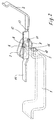
- FIG. 1 to 3 is a first embodiment of the invention Protective conductor connection shown, in which an essentially ⁇ -like clamping spring 3 the leg 5 of the mounting rail 1 non-positively on the section 6 of the Specifies busbar 2.
- FIG. 2 is an exploded view in FIG shown as a whole with 4 terminal block, the busbar 2 and the clamping spring 6 receives in a receiving space 7 and their further function basically known and of no further importance for the present invention is. Therefore, the designation as a whole is denoted by 4 Terminal block only received insofar as the fixing of the busbar 2 and the clamping spring 3 are affected.
- the mounting rail 1 is in the form of a hat-shaped design represented with symmetrical legs 5, as they are as a DIN mounting rail is widely used. Also in exploded view are approximate the later determination position the busbar 2 and the spring 3 shown.
- the busbar 2 is formed from a flat sheet metal section, which by different Bends and cutouts as well as bends an electrical connection between a connection point in the terminal block that is not important here 4 and the mounting rail 1 forms.
- the busbar 2 In the area of section 6 of the busbar 2, the intended to lie on the leg 5 of the mounting rail 1 comes, the busbar 2 is flat to provide the fullest possible support to effect on the bar 5 of the mounting rail 1.
- this section 6 on the one hand a support surface 14 by extending the Busbar 2 formed, on the other hand an extension of the busbar 2 in Direction to a connection point designed, for example, as a tension spring connection available.
- a side web 12 which is a connection forms between the two opposite ends of the busbar 2, because for the passage of the clamping spring 3 in the intended position, a recess 11 is formed in the busbar 2 so that the clamping spring 3 transversely to the extent of Carrier rail 1 can be plugged onto the leg 5 when snapping on.
- a side web 12 for the manufacture of the side web 12 Undercut 13 arranged.
- the ⁇ -shaped clamping spring consists of an essentially flat spring leg 8, another spring leg 9 with a linear support area in the area of the contact point 6, the spring legs 8 and 9 with one another by an essentially ⁇ -like curve, in one piece with the spring legs 8 and 9 formed sheet metal strip is connected. Still is at the end of the clamping spring 3, the line-like contact in the area of Contact point 16 is assigned, a support tab 10 is formed, with which the Clamping spring 3 bears against the corresponding housing contours of the terminal block 4 and can support.
- FIG. 2 in which the important parts of the clamping effect of the Protective conductor connection are shown, is in the intended position of Clamping spring 3, busbar 2 and leg 5 of the mounting rail 1 of the leg 5 and the busbar 2 in the area of section 6 between the spring legs 8 and 9 inserted, whereby the spring force between the spring legs 8 and 9 exclusively in the direction perpendicular to the leg 5 and thus in FIG. 2 in the vertical acts on the contact partners 2 and 5.
- the clamp spring 3 is regarding the assignment of the spring legs 8 and 9 designed so that the distance between the spring legs 8 and 9 in the unloaded state, d. H. that is, before snapping on the terminal block 4 on the mounting rail 1 take a smaller distance than the Form the thickness of the stacked contact partner legs 5 and 2 busbar.
- Figure 3 is the properly installed state of the terminal block 4 with the inserted busbar 2 and the clamping spring 3, the Leg 5 of the mounting rail 1 after snapping on the terminal block 4 in the area the contact point 16 is arranged. You can clearly see the effect again the support elements 15, the clamping spring 3 and the busbar 2 in the receiving space 7 hold on securely.
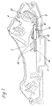
- FIGS. 4 and 5 show a further embodiment of the invention
- Protective conductor connection shown differing from the embodiment 1 to 3 an essentially U-shaped clamping spring 3, more precisely a spring clip angled in the shape of the large Greek letter ⁇ 3 is used.
- an essentially U-shaped clamping spring 3 more precisely a spring clip angled in the shape of the large Greek letter ⁇ 3 is used.
- the two spring legs 8 and 9 has opposite, by a connecting, U-shaped curved area are fixed to each other in one piece, can be a particularly simple embodiment the clamping spring 3 can be reached.
- it is essentially U-shaped curved clamping spring 3 a little ⁇ -shaped, so that in the area of Contact point 16 of the spring legs 8 and 9 has a linear contact on both sides with the contact partners tavern 5 and busbar 2 in the area of the section 6 results.
- the spring force is very precisely in the contact partner initiated, by the position not shown in Figures 4 and 5 of the Clamping spring 3 in the housing of the terminal block 4 close to the clamp Edge of the leg 5 or further in the inner region of the leg 5 can take place.
- the clamping spring 3 again passes through the busbar 2 in the region of the recess 11, for which purpose in a manner analogous to Figures 1 to 3, a side web 12 Connection of the two parts of the busbar 2 is formed.
Applications Claiming Priority (2)
| Application Number | Priority Date | Filing Date | Title |
|---|---|---|---|
| DE19708911A DE19708911C1 (de) | 1997-03-05 | 1997-03-05 | Schutzleiteranschluß |
| DE19708911 | 1997-03-05 |
Publications (3)
| Publication Number | Publication Date |
|---|---|
| EP0863577A2 true EP0863577A2 (fr) | 1998-09-09 |
| EP0863577A3 EP0863577A3 (fr) | 1999-06-23 |
| EP0863577B1 EP0863577B1 (fr) | 2001-11-28 |
Family
ID=7822275
Family Applications (1)
| Application Number | Title | Priority Date | Filing Date |
|---|---|---|---|
| EP98102189A Expired - Lifetime EP0863577B1 (fr) | 1997-03-05 | 1998-02-09 | Borne pour conducteur de protection |
Country Status (3)
| Country | Link |
|---|---|
| EP (1) | EP0863577B1 (fr) |
| AT (1) | ATE209829T1 (fr) |
| DE (2) | DE19708911C1 (fr) |
Cited By (2)
| Publication number | Priority date | Publication date | Assignee | Title |
|---|---|---|---|---|
| FR2803440A1 (fr) * | 2000-01-04 | 2001-07-06 | Entrelec Sa | Ressort de fixation d'un bloc de jonction ou similaire sur un rail |
| KR101370255B1 (ko) * | 2010-11-15 | 2014-03-05 | 야자키 소교 가부시키가이샤 | 단자 접속 구조 |
Families Citing this family (3)
| Publication number | Priority date | Publication date | Assignee | Title |
|---|---|---|---|---|
| DE19818704C1 (de) * | 1998-04-19 | 1999-11-04 | Wago Verwaltungs Gmbh | Montagefuß mit Schutzleiterfunktion für elektr. Klemmen |
| DE10041279C2 (de) * | 2000-08-22 | 2002-11-21 | Phoenix Contact Gmbh & Co | Elektrische Reihenklemme |
| DE10218567C5 (de) * | 2002-04-26 | 2010-08-05 | Wieland Electric Gmbh | Anschlusssystem |
Citations (3)
| Publication number | Priority date | Publication date | Assignee | Title |
|---|---|---|---|---|
| DE7613429U1 (de) * | 1976-04-28 | 1976-12-02 | Phoenix Elektrizitaetsgesellschaft H. Knuemann & Co., 4933 Blomberg | Elektrische Reihenklemme |
| EP0556560A1 (fr) * | 1992-02-18 | 1993-08-25 | Woertz Ag | Borne à fil de terre |
| US5480310A (en) * | 1993-10-28 | 1996-01-02 | Raychem Corporation | Connector ground clip |
Family Cites Families (2)
| Publication number | Priority date | Publication date | Assignee | Title |
|---|---|---|---|---|
| DE4203184C3 (de) * | 1992-02-05 | 1996-11-21 | Weidmueller Interface | Schutzleiterklemme |
| DE19631436C1 (de) * | 1996-08-03 | 1997-10-09 | Weidmueller Interface | Schutzleiteranschluß insbesondere für Reihenklemmen |
-
1997
- 1997-03-05 DE DE19708911A patent/DE19708911C1/de not_active Expired - Fee Related
-
1998
- 1998-02-09 DE DE59802195T patent/DE59802195D1/de not_active Expired - Lifetime
- 1998-02-09 EP EP98102189A patent/EP0863577B1/fr not_active Expired - Lifetime
- 1998-02-09 AT AT98102189T patent/ATE209829T1/de not_active IP Right Cessation
Patent Citations (3)
| Publication number | Priority date | Publication date | Assignee | Title |
|---|---|---|---|---|
| DE7613429U1 (de) * | 1976-04-28 | 1976-12-02 | Phoenix Elektrizitaetsgesellschaft H. Knuemann & Co., 4933 Blomberg | Elektrische Reihenklemme |
| EP0556560A1 (fr) * | 1992-02-18 | 1993-08-25 | Woertz Ag | Borne à fil de terre |
| US5480310A (en) * | 1993-10-28 | 1996-01-02 | Raychem Corporation | Connector ground clip |
Cited By (4)
| Publication number | Priority date | Publication date | Assignee | Title |
|---|---|---|---|---|
| FR2803440A1 (fr) * | 2000-01-04 | 2001-07-06 | Entrelec Sa | Ressort de fixation d'un bloc de jonction ou similaire sur un rail |
| US6471552B2 (en) | 2000-01-04 | 2002-10-29 | Entrelec S.A. | Spring for securing a terminal block or the like to a rail |
| DE10100182B4 (de) * | 2000-01-04 | 2006-12-14 | Entrelec Sa | Feder zur Befestigung einer Reihenklemme an einer Schiene |
| KR101370255B1 (ko) * | 2010-11-15 | 2014-03-05 | 야자키 소교 가부시키가이샤 | 단자 접속 구조 |
Also Published As
| Publication number | Publication date |
|---|---|
| EP0863577B1 (fr) | 2001-11-28 |
| DE59802195D1 (de) | 2002-01-10 |
| ATE209829T1 (de) | 2001-12-15 |
| EP0863577A3 (fr) | 1999-06-23 |
| DE19708911C1 (de) | 1998-07-30 |
Similar Documents
| Publication | Publication Date | Title |
|---|---|---|
| DE10315668B4 (de) | Anschlußklemme | |
| EP0806811A2 (fr) | Connecteur à ressort ayant un élément de butée enfichable | |
| DE102004030085A1 (de) | Klemme zum Anschluß elektrischer Leiter | |
| EP1536519A1 (fr) | Borne de raccordement pour conducteur | |
| DE102016208291B4 (de) | Federklammer, Montagewerkzeug sowie Verfahren zum Fixieren von Kontaktpartnern und Verbindungssystem zum Herstellen einer elektrischen und mechanischen Verbindung zwischen Kontaktpartnern | |
| DE102013109640A1 (de) | Federkraftanschlussklemme und Klemmenbauelement | |
| DE3828277C2 (de) | An einer Tragschiene anbringbare Schalteinheit mit zwei elektromagnetischen Kontakteinrichtungen | |
| EP0875084B1 (fr) | Dispositif de connexion electrique du bati ou du corps d'une armoire de distribution avec la porte | |
| EP1763109B1 (fr) | Support d'agraffe de contact pour le montage sur une barre électrique et dispositif du support sur celle-ci | |
| DE102019125675A1 (de) | Elektrische Anschlussanordnung umfassend eine Stromschiene mit einer daran angeschlossenen Leiteranordnung und einem Klammerelement | |
| EP1394902B1 (fr) | Borne de connection | |
| DE2619035C2 (de) | Schraubenlose Anschluß- und/oder Verbindungsklemme | |
| EP0086316B1 (fr) | Dispositif à contact enfichable pour la réalisation d'une connexion électrique entre deux barres omnibus | |
| EP0863577B1 (fr) | Borne pour conducteur de protection | |
| DE2854850A1 (de) | Schraubenlose anschlussklemme | |
| EP1710863A1 (fr) | Elément de contact avec un ressort de protection du fil | |
| EP1523069A1 (fr) | Ressort de contact pour amplificateur d'antenne | |
| EP0928504B1 (fr) | Organe de contact par raccord a double dispositif perce-isolant | |
| DE2852829A1 (de) | Schnellmontagesockel aus kunststoff | |
| EP1182735B1 (fr) | Réglette d'interconnexion électrique | |
| DE3126535C2 (de) | Elektrische Reihenklemme | |
| DE19539958B4 (de) | Kontakt | |
| DE102006041803A1 (de) | Vorrichtung zur Befestigung eines Gerätes an einer Tragschiene | |
| EP0806812A2 (fr) | Connecteur à ressort pour conducteur électrique ayant des nervures de butée | |
| EP0456984B1 (fr) | Interrupteur à fiches |
Legal Events
| Date | Code | Title | Description |
|---|---|---|---|
| PUAI | Public reference made under article 153(3) epc to a published international application that has entered the european phase |
Free format text: ORIGINAL CODE: 0009012 |
|
| 17P | Request for examination filed |
Effective date: 19980214 |
|
| AK | Designated contracting states |
Kind code of ref document: A2 Designated state(s): AT CH DE FR GB IT LI |
|
| AX | Request for extension of the european patent |
Free format text: AL;LT;LV;MK;RO;SI |
|
| PUAL | Search report despatched |
Free format text: ORIGINAL CODE: 0009013 |
|
| AK | Designated contracting states |
Kind code of ref document: A3 Designated state(s): AT BE CH DE DK ES FI FR GB GR IE IT LI LU MC NL PT SE |
|
| AX | Request for extension of the european patent |
Free format text: AL;LT;LV;MK;RO;SI |
|
| RIC1 | Information provided on ipc code assigned before grant |
Free format text: 6H 01R 9/26 A, 6H 01R 4/48 B |
|
| AKX | Designation fees paid |
Free format text: AT CH DE FR GB IT LI |
|
| 17Q | First examination report despatched |
Effective date: 20000202 |
|
| GRAG | Despatch of communication of intention to grant |
Free format text: ORIGINAL CODE: EPIDOS AGRA |
|
| GRAG | Despatch of communication of intention to grant |
Free format text: ORIGINAL CODE: EPIDOS AGRA |
|
| GRAH | Despatch of communication of intention to grant a patent |
Free format text: ORIGINAL CODE: EPIDOS IGRA |
|
| GRAH | Despatch of communication of intention to grant a patent |
Free format text: ORIGINAL CODE: EPIDOS IGRA |
|
| GRAA | (expected) grant |
Free format text: ORIGINAL CODE: 0009210 |
|
| AK | Designated contracting states |
Kind code of ref document: B1 Designated state(s): AT CH DE FR GB IT LI |
|
| REF | Corresponds to: |
Ref document number: 209829 Country of ref document: AT Date of ref document: 20011215 Kind code of ref document: T |
|
| REG | Reference to a national code |
Ref country code: CH Ref legal event code: NV Representative=s name: ISLER & PEDRAZZINI AG Ref country code: CH Ref legal event code: EP |
|
| REG | Reference to a national code |
Ref country code: GB Ref legal event code: IF02 |
|
| REF | Corresponds to: |
Ref document number: 59802195 Country of ref document: DE Date of ref document: 20020110 |
|
| GBT | Gb: translation of ep patent filed (gb section 77(6)(a)/1977) |
Effective date: 20020306 |
|
| ET | Fr: translation filed | ||
| PLBE | No opposition filed within time limit |
Free format text: ORIGINAL CODE: 0009261 |
|
| STAA | Information on the status of an ep patent application or granted ep patent |
Free format text: STATUS: NO OPPOSITION FILED WITHIN TIME LIMIT |
|
| 26N | No opposition filed | ||
| PGFP | Annual fee paid to national office [announced via postgrant information from national office to epo] |
Ref country code: GB Payment date: 20040130 Year of fee payment: 7 |
|
| PGFP | Annual fee paid to national office [announced via postgrant information from national office to epo] |
Ref country code: CH Payment date: 20040203 Year of fee payment: 7 |
|
| PGFP | Annual fee paid to national office [announced via postgrant information from national office to epo] |
Ref country code: AT Payment date: 20040204 Year of fee payment: 7 |
|
| PG25 | Lapsed in a contracting state [announced via postgrant information from national office to epo] |
Ref country code: GB Free format text: LAPSE BECAUSE OF NON-PAYMENT OF DUE FEES Effective date: 20050209 Ref country code: AT Free format text: LAPSE BECAUSE OF NON-PAYMENT OF DUE FEES Effective date: 20050209 |
|
| PG25 | Lapsed in a contracting state [announced via postgrant information from national office to epo] |
Ref country code: LI Free format text: LAPSE BECAUSE OF NON-PAYMENT OF DUE FEES Effective date: 20050228 Ref country code: CH Free format text: LAPSE BECAUSE OF NON-PAYMENT OF DUE FEES Effective date: 20050228 |
|
| GBPC | Gb: european patent ceased through non-payment of renewal fee |
Effective date: 20050209 |
|
| REG | Reference to a national code |
Ref country code: CH Ref legal event code: PL |
|
| PGFP | Annual fee paid to national office [announced via postgrant information from national office to epo] |
Ref country code: IT Payment date: 20080223 Year of fee payment: 11 |
|
| PGFP | Annual fee paid to national office [announced via postgrant information from national office to epo] |
Ref country code: FR Payment date: 20080214 Year of fee payment: 11 |
|
| REG | Reference to a national code |
Ref country code: FR Ref legal event code: ST Effective date: 20091030 |
|
| PG25 | Lapsed in a contracting state [announced via postgrant information from national office to epo] |
Ref country code: FR Free format text: LAPSE BECAUSE OF NON-PAYMENT OF DUE FEES Effective date: 20090302 |
|
| PG25 | Lapsed in a contracting state [announced via postgrant information from national office to epo] |
Ref country code: IT Free format text: LAPSE BECAUSE OF NON-PAYMENT OF DUE FEES Effective date: 20090209 |
|
| PGFP | Annual fee paid to national office [announced via postgrant information from national office to epo] |
Ref country code: DE Payment date: 20150219 Year of fee payment: 18 |
|
| REG | Reference to a national code |
Ref country code: DE Ref legal event code: R119 Ref document number: 59802195 Country of ref document: DE |
|
| PG25 | Lapsed in a contracting state [announced via postgrant information from national office to epo] |
Ref country code: DE Free format text: LAPSE BECAUSE OF NON-PAYMENT OF DUE FEES Effective date: 20160901 |