EP0863577A2 - Protective wire connection for motor - Google Patents
Protective wire connection for motor Download PDFInfo
- Publication number
- EP0863577A2 EP0863577A2 EP98102189A EP98102189A EP0863577A2 EP 0863577 A2 EP0863577 A2 EP 0863577A2 EP 98102189 A EP98102189 A EP 98102189A EP 98102189 A EP98102189 A EP 98102189A EP 0863577 A2 EP0863577 A2 EP 0863577A2
- Authority
- EP
- European Patent Office
- Prior art keywords
- protective conductor
- mounting rail
- busbar
- spring
- clamping spring
- Prior art date
- Legal status (The legal status is an assumption and is not a legal conclusion. Google has not performed a legal analysis and makes no representation as to the accuracy of the status listed.)
- Granted
Links
- 230000001681 protective effect Effects 0.000 title claims description 39
- 239000004020 conductor Substances 0.000 claims abstract description 50
- 239000002184 metal Substances 0.000 claims abstract description 13
- 239000011810 insulating material Substances 0.000 claims abstract description 7
- 230000000694 effects Effects 0.000 description 5
- 238000012423 maintenance Methods 0.000 description 3
- 238000004519 manufacturing process Methods 0.000 description 3
- 239000000463 material Substances 0.000 description 2
- 230000005540 biological transmission Effects 0.000 description 1
- 238000010276 construction Methods 0.000 description 1
- 230000007423 decrease Effects 0.000 description 1
- 230000003247 decreasing effect Effects 0.000 description 1
- 238000006073 displacement reaction Methods 0.000 description 1
- 230000002349 favourable effect Effects 0.000 description 1
- 238000009434 installation Methods 0.000 description 1
- 230000014759 maintenance of location Effects 0.000 description 1
- 238000012986 modification Methods 0.000 description 1
- 230000004048 modification Effects 0.000 description 1
- 230000000284 resting effect Effects 0.000 description 1
Images


Classifications
-
- H—ELECTRICITY
- H01—ELECTRIC ELEMENTS
- H01R—ELECTRICALLY-CONDUCTIVE CONNECTIONS; STRUCTURAL ASSOCIATIONS OF A PLURALITY OF MUTUALLY-INSULATED ELECTRICAL CONNECTING ELEMENTS; COUPLING DEVICES; CURRENT COLLECTORS
- H01R9/00—Structural associations of a plurality of mutually-insulated electrical connecting elements, e.g. terminal strips or terminal blocks; Terminals or binding posts mounted upon a base or in a case; Bases therefor
- H01R9/22—Bases, e.g. strip, block, panel
- H01R9/24—Terminal blocks
- H01R9/26—Clip-on terminal blocks for side-by-side rail- or strip-mounting
- H01R9/2691—Clip-on terminal blocks for side-by-side rail- or strip-mounting with ground wire connection to the rail
-
- H—ELECTRICITY
- H01—ELECTRIC ELEMENTS
- H01R—ELECTRICALLY-CONDUCTIVE CONNECTIONS; STRUCTURAL ASSOCIATIONS OF A PLURALITY OF MUTUALLY-INSULATED ELECTRICAL CONNECTING ELEMENTS; COUPLING DEVICES; CURRENT COLLECTORS
- H01R4/00—Electrically-conductive connections between two or more conductive members in direct contact, i.e. touching one another; Means for effecting or maintaining such contact; Electrically-conductive connections having two or more spaced connecting locations for conductors and using contact members penetrating insulation
- H01R4/28—Clamped connections, spring connections
- H01R4/48—Clamped connections, spring connections utilising a spring, clip, or other resilient member
- H01R4/4809—Clamped connections, spring connections utilising a spring, clip, or other resilient member using a leaf spring to bias the conductor toward the busbar
Definitions
- the invention relates to a protective conductor connection for by means of a latching arrangement according to their insulating material housing with a mounting rail that can be locked in place Generic term of claim 1.
- Protective conductor connections have to perform a safety function in switchgear, because the protective conductor contact when detecting impermissible voltages and Performs a central safety function. Therefore must Protective conductor connections also with regard to their operating behavior in impermissible Operating situations, for example in the event of a fire, may be able to function even then at least for a certain time.
- Protective conductor connections are also known which have a fastening foot and a contact foot completely made of metal (DE 42 03 184 C3), the potential leading parts, for example, a conductor rail on this fastening and Contact foot are set. Furthermore, this metal mounting and contact foot the maintenance of the protective conductor function even over a longer period of time for example in the event of a fire, but such protective conductor connections are required a high cost of materials with numerous manufacturing steps. This contact and and mounting feet also have a high volume, so that valuable installation space is lost in the small-volume switchgear.
- EP 0 556 560 A1 also discloses a protective conductor terminal with a metallic fastening and contact foot, in which the foot is in the connection area to the mounting rail rests with plate-shaped elements on the two mounting rail legs and a substantially U-shaped spring is integrated in the foot, which the grips around and under both carrier rail legs.
- the spring also has the contact function in normal operation how to perform the holding function and must be based on it in their overall strength be interpreted.
- the spring force depends on the width of the mounting rail. It decreases with decreasing mounting rail widths, though one does not correspondingly in a particularly disadvantageous manner for each mounting rail width wants to provide separate springs.
- the present invention has for its object a protective conductor connection the generic type in that its protective conductor function even in non-operational conditions such as in the event of a fire reasonable period of time remains guaranteed without the locking and holding devices of the protective conductor connection must consist entirely of metal and at the same time a safe guarantee of the pressing of the potential leading parts to the mounting rail is guaranteed.
- the clamping spring with its two resiliently connected Spring legs a section of the track piece after snapping on Terminal block by means of its housing-side locking contour on the mounting rail on the assigned area presses one of the legs of the mounting rail, results from the spring action of such a clamping spring an extremely safe contact this section of the conductor rail piece on the surface of the leg the mounting rail.
- the spring force can be tailored to the requirements, regardless of the dimensions of the mounting rail. In normal operation the holding function of the locking of the insulating material housing on the mounting rail accepted.
- the clamping spring consists of an essential U-shaped sheet metal strip.
- a spring clip is very simply constructed and can be selected by appropriate choice of materials and dimensions designed in a technically simple manner to the desired spring forces will. This also applies to the realization of a point or line Contact between the clamping spring and the mounting rail leg or section of the Track piece. As a result, the position of the clamping force is relative to the Contact partners can be specified precisely. Otherwise possible displacement forces can also occur for example due to insufficiently bent clamping springs be avoided so that the contact partners do not move to each other inadmissibly.
- the clamping spring is essentially of one like the Greek letter ⁇ formed sheet metal strip, where hereby an even further influence on the spring properties of the clamping spring is achievable in relation to the U-shaped design.
- Favorable pre-tensioning of the clamping spring is realized by additional webs on the ⁇ -shape will.
- this ⁇ -shaped clamping spring this is in the area the clamping point between the leg of the mounting rail and the section of the busbar piece shaped so that between the clamping spring and the Conductor rail section a flat contact and a point or line-shaped Contact between the clamping spring and the leg of the mounting rail is achieved. This allows a particularly safe support of the clamping forces with a defined force transmission of the clamping spring into the contact partner.
- the clamping spring on assigned functional surfaces in the insulating housing to store, the relaxed distance between the spring legs of the clamping spring is less than the assigned dimensions of the leg of the mounting rail and the section of the busbar piece. This can be achieved that when the protective conductor connection is snapped on, insert the clamping spring of the leg of the mounting rail is biased and this the holding force of the self-holding Specifies the clamping spring in the operating state.
- the fixing of the conductor rail piece on only one leg of the mounting rail basically enables the creation of a universal design for mounting rails different dimensions, always using the same clamping spring, whereby the manufacture and storage of such protective conductor connections improved.
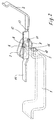
- FIG. 1 to 3 is a first embodiment of the invention Protective conductor connection shown, in which an essentially ⁇ -like clamping spring 3 the leg 5 of the mounting rail 1 non-positively on the section 6 of the Specifies busbar 2.
- FIG. 2 is an exploded view in FIG shown as a whole with 4 terminal block, the busbar 2 and the clamping spring 6 receives in a receiving space 7 and their further function basically known and of no further importance for the present invention is. Therefore, the designation as a whole is denoted by 4 Terminal block only received insofar as the fixing of the busbar 2 and the clamping spring 3 are affected.
- the mounting rail 1 is in the form of a hat-shaped design represented with symmetrical legs 5, as they are as a DIN mounting rail is widely used. Also in exploded view are approximate the later determination position the busbar 2 and the spring 3 shown.
- the busbar 2 is formed from a flat sheet metal section, which by different Bends and cutouts as well as bends an electrical connection between a connection point in the terminal block that is not important here 4 and the mounting rail 1 forms.
- the busbar 2 In the area of section 6 of the busbar 2, the intended to lie on the leg 5 of the mounting rail 1 comes, the busbar 2 is flat to provide the fullest possible support to effect on the bar 5 of the mounting rail 1.
- this section 6 on the one hand a support surface 14 by extending the Busbar 2 formed, on the other hand an extension of the busbar 2 in Direction to a connection point designed, for example, as a tension spring connection available.
- a side web 12 which is a connection forms between the two opposite ends of the busbar 2, because for the passage of the clamping spring 3 in the intended position, a recess 11 is formed in the busbar 2 so that the clamping spring 3 transversely to the extent of Carrier rail 1 can be plugged onto the leg 5 when snapping on.
- a side web 12 for the manufacture of the side web 12 Undercut 13 arranged.
- the ⁇ -shaped clamping spring consists of an essentially flat spring leg 8, another spring leg 9 with a linear support area in the area of the contact point 6, the spring legs 8 and 9 with one another by an essentially ⁇ -like curve, in one piece with the spring legs 8 and 9 formed sheet metal strip is connected. Still is at the end of the clamping spring 3, the line-like contact in the area of Contact point 16 is assigned, a support tab 10 is formed, with which the Clamping spring 3 bears against the corresponding housing contours of the terminal block 4 and can support.
- FIG. 2 in which the important parts of the clamping effect of the Protective conductor connection are shown, is in the intended position of Clamping spring 3, busbar 2 and leg 5 of the mounting rail 1 of the leg 5 and the busbar 2 in the area of section 6 between the spring legs 8 and 9 inserted, whereby the spring force between the spring legs 8 and 9 exclusively in the direction perpendicular to the leg 5 and thus in FIG. 2 in the vertical acts on the contact partners 2 and 5.
- the clamp spring 3 is regarding the assignment of the spring legs 8 and 9 designed so that the distance between the spring legs 8 and 9 in the unloaded state, d. H. that is, before snapping on the terminal block 4 on the mounting rail 1 take a smaller distance than the Form the thickness of the stacked contact partner legs 5 and 2 busbar.
- Figure 3 is the properly installed state of the terminal block 4 with the inserted busbar 2 and the clamping spring 3, the Leg 5 of the mounting rail 1 after snapping on the terminal block 4 in the area the contact point 16 is arranged. You can clearly see the effect again the support elements 15, the clamping spring 3 and the busbar 2 in the receiving space 7 hold on securely.
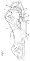
- FIGS. 4 and 5 show a further embodiment of the invention
- Protective conductor connection shown differing from the embodiment 1 to 3 an essentially U-shaped clamping spring 3, more precisely a spring clip angled in the shape of the large Greek letter ⁇ 3 is used.
- an essentially U-shaped clamping spring 3 more precisely a spring clip angled in the shape of the large Greek letter ⁇ 3 is used.
- the two spring legs 8 and 9 has opposite, by a connecting, U-shaped curved area are fixed to each other in one piece, can be a particularly simple embodiment the clamping spring 3 can be reached.
- it is essentially U-shaped curved clamping spring 3 a little ⁇ -shaped, so that in the area of Contact point 16 of the spring legs 8 and 9 has a linear contact on both sides with the contact partners tavern 5 and busbar 2 in the area of the section 6 results.
- the spring force is very precisely in the contact partner initiated, by the position not shown in Figures 4 and 5 of the Clamping spring 3 in the housing of the terminal block 4 close to the clamp Edge of the leg 5 or further in the inner region of the leg 5 can take place.
- the clamping spring 3 again passes through the busbar 2 in the region of the recess 11, for which purpose in a manner analogous to Figures 1 to 3, a side web 12 Connection of the two parts of the busbar 2 is formed.
Abstract
Description
Die Erfindung betrifft einen Schutzleiteranschluß für mittels einer Rastanordnung ihres Isolierstoff-Gehäuses mit einer Tragschiene verrastbarem Einklemmen gemäß Gattungsbegriff des Anspruches 1.The invention relates to a protective conductor connection for by means of a latching arrangement according to their insulating material housing with a mounting rail that can be locked in place Generic term of claim 1.
Schutzleiteranschlüsse haben in Schaltanlagen eine Sicherheitsfunktion zu erfüllen, da der Schutzleiterkontakt bei der Erkennung von unzulässigen Spannungen und Signalzuständen eine zentrale Sicherheitsfunktion wahrnimmt. Daher müssen Schutzleiteranschlüsse auch hinsichtlich ihres Betriebsverhaltens in unzulässigen Betriebssituationen, beispielsweise auch im Brandfall, in der Lage sein, ihre Funktion auch dann zumindest eine gewisse Zeitlang zu gewährleisten.Protective conductor connections have to perform a safety function in switchgear, because the protective conductor contact when detecting impermissible voltages and Performs a central safety function. Therefore must Protective conductor connections also with regard to their operating behavior in impermissible Operating situations, for example in the event of a fire, may be able to function even then at least for a certain time.
Es sind Schutzleiteranschlüsse bekannt (DE-GM 76 13 429), bei denen die Haltefunktion des Schutzleiteranschlusses in der Ausführung als Reihenklemmenanschluß auf einer Tragschiene durch aus Isolierstoff bestehende Gehäuseteile der Reihenklemme gewährleistet wird. Die Stromschiene des Schutzleiteranschlusses kontaktiert die Tragschiene unmittelbar. Die konstruktive Ausgestaltung ist dabei so getroffen, daß im Notfall eine gewisse Aufrechterhaltung der Schutzleiterfunktion bei Ausfall der Haltefunktion des Gehäuses nicht gewährleistet ist, zumal auch insoweit noch gehäuseseitige Abstützungen für die Kontaktfunktion herangezogen werden.There are protective conductor connections known (DE-GM 76 13 429) in which the holding function of the protective conductor connection in the version as a terminal block connection on a mounting rail through housing parts of the terminal block made of insulating material is guaranteed. The conductor rail of the protective conductor connection makes contact the mounting rail immediately. The structural design is so met that in an emergency some maintenance of the protective conductor function Failure of the holding function of the housing is not guaranteed, especially since supports on the housing side can still be used for the contact function.
Es sind ferner Schutzleiteranschlüsse bekannt, die einen Befestigungs- und Kontaktfuß vollständig aus Metall aufweisen (DE 42 03 184 C3), wobei die Potential führenden Teile beispielsweise einer Stromschiene an diesem Befestigungs- und Kontaktfuß festgelegt sind. Ferner leistet dieser metallische Befestigungs- und Kontaktfuß die Aufrechterhaltung der Schutzleiterfunktion auch über einen längeren Zeitraum beispielsweise im Brandfall, doch benötigen derartige Schutzleiteranschlüsse einen hohen Materialaufwand mit zahlreichen Fertigungsschritten. Diese Kontakt- und und Befestigungsfüße haben auch ein hohes Bauvolumen, so daß wertvoller Einbauraum in den kleinvolumigen Schaltanlagen verlorengeht. Dabei ist auch ein derartiger Schutzleiteranschluß in der DE 196 31 436 vorgeschlagen worden, bei dem der metallische Befestigungs- und Kontaktfuß mit einer zusätzlichen Feder versehen ist, die einen seiner Abschnitte unter Vorspannung an die Tragschiene einer Schaltanlage andrückt und bewirkt, daß auch bei maßlichen Abweichungen zwischen den Rastkonturen und zugeordneten Tragschienenkonturen eine sichere Festlegung erfolgen kann.Protective conductor connections are also known which have a fastening foot and a contact foot completely made of metal (DE 42 03 184 C3), the potential leading parts, for example, a conductor rail on this fastening and Contact foot are set. Furthermore, this metal mounting and contact foot the maintenance of the protective conductor function even over a longer period of time for example in the event of a fire, but such protective conductor connections are required a high cost of materials with numerous manufacturing steps. This contact and and mounting feet also have a high volume, so that valuable installation space is lost in the small-volume switchgear. There is also one Protective conductor connection in DE 196 31 436 has been proposed, in which the metallic Fastening and contact foot is provided with an additional spring that one of its sections under tension on the mounting rail of a switchgear presses and causes that even with dimensional deviations between the locking contours and assigned carrier rail contours are securely fixed can.
Aus der EP 0 556 560 A1 ist ferner eine Schutzleiterklemme mit metallischem Befestigungs- und Kontaktfuß bekannt, bei dem der Fuß im Anschlußbereich zur Tragschiene mit plattenförmigen Elementen auf den beiden Tragschienenschenkeln aufliegt und in dem Fuß eine im wesentlichen U-förmige Feder integriert ist, die die beiden Tragschienenschenkel um- und untergreift. Auch hier liegt eine komplizierte und teure Konstruktion im Bereich des metallischen Befestigungs- und Kontaktfußes vor. Die Feder hat dabei darüber in aus im Normalbetrieb sowohl die Kontaktfunktion wie die Haltefunktion zu erfüllen und muß in ihrer Gesamtkraft entsprechend darauf ausgelegt werden. Darüber hinaus ist hier die Federkraft abhängig von der Tragschienenbreite. Sie verringert sich mit abnehmenden Tragschienenbreiten, wenn man nicht in besonders nachteiliger Weise für jede Tragschienenbreite entsprechend gesonderte Federn vorsehen will.EP 0 556 560 A1 also discloses a protective conductor terminal with a metallic fastening and contact foot, in which the foot is in the connection area to the mounting rail rests with plate-shaped elements on the two mounting rail legs and a substantially U-shaped spring is integrated in the foot, which the grips around and under both carrier rail legs. There is also a complicated one here and expensive construction in the area of the metal mounting and contact foot in front. The spring also has the contact function in normal operation how to perform the holding function and must be based on it in their overall strength be interpreted. In addition, the spring force depends on the width of the mounting rail. It decreases with decreasing mounting rail widths, though one does not correspondingly in a particularly disadvantageous manner for each mounting rail width wants to provide separate springs.
Der vorliegenden Erfindung liegt die Aufgabe zugrunde, einen Schutzleiteranschluß der gattungsgemäßen Art dahingehend weiterzubilden, daß seine Schutzleiterfunktion auch in betriebsunüblichen Zuständen wie beispielweise im Brandfall über einen angemessene Zeitraum gewährleistet bleibt, ohne daß die Verrastungs- und Halteeinrichtungen des Schutzleiteranschlusses vollständig aus Metall bestehen müssen und bei dem gleichzeitig eine sichere Gewährleistung der Anpressung der Potential führenden Teile an die Tragschiene gewährleistet ist. The present invention has for its object a protective conductor connection the generic type in that its protective conductor function even in non-operational conditions such as in the event of a fire reasonable period of time remains guaranteed without the locking and holding devices of the protective conductor connection must consist entirely of metal and at the same time a safe guarantee of the pressing of the potential leading parts to the mounting rail is guaranteed.
Die erfindungsgemäße Lösung ergibt sich aus dem Anspruch 1.The solution according to the invention results from claim 1.
Dadurch, daß die Klemmfeder mit ihren zwei federnd miteinander verbundenen Federschenkeln einen Abschnitt des Stromschienenstückes nach dem Aufrasten der Reihenklemme mittels ihrer gehäuseseitigen Rastkontur auf die Tragschiene auf die zugeordnete Fläche eines der Schenkels der Tragschiene preßt, ergibt sich aufgrund der Federwirkung einer derartigen Klemmfeder eine außerordentlich sichere Kontaktierung dieses Abschnittes des Stromschienenstückes auf der Fläche des Schenkels der Tragschiene. Die Federkraft kann exakt auf die Erfordernisse, und zwar unabhängig von den Dimensionen der Tragschiene, ausgelegt werden. Im Normalbetrieb wird die Haltefunktion von der Verrastung des Isolierstoffgehäuses auf der Tragschiene übernommen. Dank der erfindungsgemäßen Ausgestaltung ist jedoch eine so zuverlässige Anpressung und damit nicht nur Kontaktierung, sondern auch Festhaltung des Stromschienenabschnittes an der Tragschiene erreicht, daß auch für den Fall, daß beispielsweise im Brandfall die Rastkontur des Isolierstoffgehäuses ihre Wirkung verliert, für eine ausreichende Zeit die Stromschiene kontaktierend an den Tragschienenschenkel angepreßt bleibt und damit auch dann die Schutzleiterfunktion noch über einen ausreichenden Zeitraum gewährleistet bleibt. Darüber hinaus ergibt sich ein einfacher konstruktiver Aufbau, der auch kleinvolumig baut. Durch die flächige Anpressung des Abschnittes des Stromschienenstückes an den Tragschienenschenkel ergibt sich hier auch nur ein geringer Übergangswiderstand. Die Funktionsaufrechterhaltung ist bei dieser Ausgestaltung auch deswegen so sicher, weil die Klemmfeder als solche aus sich heraus die Federkraft aufbringt, ohne daß sie beispielsweise an Gehäuseabschnitten des Isolierstoffgehäuses als Gegenlager abgestützt werden müßte.Characterized in that the clamping spring with its two resiliently connected Spring legs a section of the track piece after snapping on Terminal block by means of its housing-side locking contour on the mounting rail on the assigned area presses one of the legs of the mounting rail, results from the spring action of such a clamping spring an extremely safe contact this section of the conductor rail piece on the surface of the leg the mounting rail. The spring force can be tailored to the requirements, regardless of the dimensions of the mounting rail. In normal operation the holding function of the locking of the insulating material housing on the mounting rail accepted. Thanks to the design according to the invention, however, so reliable contact and not only contacting, but also retention of the busbar section on the mounting rail achieved that also for the Case that, for example, in the event of fire, the locking contour of the insulating housing Loses effect by contacting the busbar for a sufficient time Carrier rail leg remains pressed and thus also the protective conductor function remains guaranteed for a sufficient period of time. Furthermore results a simple constructive structure that also builds small volumes. Through the flat Pressing the section of the conductor rail piece onto the mounting rail leg there is only a small contact resistance here. Function maintenance is so safe with this configuration also because the Clamp spring as such applies the spring force without it, for example supported on housing sections of the insulating material housing as a counter bearing should be.
Gemäß einer bevorzugten Ausführungsform besteht die Klemmfeder aus einem im wesentlichen U-förmig gebogenen Blechstreifen. Eine derartige Klemmfeder ist sehr einfach aufgebaut und kann durch entsprechende Materialwahl und Dimensionierung in fertigungstechnisch einfacher Weise auf die gewünschten Federkräfte ausgelegt werden. Das gilt auch für die Verwirklichung einer punkt- oder linienförmigen Berührung zwischen Klemmfeder und Tragschienenschenkel bzw. Abschnitt des Stromschienenstückes. Hierdurch ist auch die Lage der Klemmkraft relativ zu den Kontaktpartnern genau vorgebbar. Auch können ansonsten mögliche Verschiebungskräfte beispielsweise aufgrund nicht ausreichend gebogener Klemmfedern vermieden werden, so daß die Kontaktpartner sich nicht unzulässig zueinander verschieben. According to a preferred embodiment, the clamping spring consists of an essential U-shaped sheet metal strip. Such a spring clip is very simply constructed and can be selected by appropriate choice of materials and dimensions designed in a technically simple manner to the desired spring forces will. This also applies to the realization of a point or line Contact between the clamping spring and the mounting rail leg or section of the Track piece. As a result, the position of the clamping force is relative to the Contact partners can be specified precisely. Otherwise possible displacement forces can also occur for example due to insufficiently bent clamping springs be avoided so that the contact partners do not move to each other inadmissibly.
In einer weiteren bevorzugten Ausgestaltung ist die Klemmfeder aus einem im wesentlichen wie der griechische Buchstabe σ gebogenen Blechstreifen gebildet, wobei hierdurch eine noch weitere Beeinflußbarkeit der Federeigenschaften der Klemmfeder im Verhältnis zu der U-förmigen Ausführung erreichbar ist. Insbesondere können durch Zusatzstege an der σ-Form günstige Vorspannungen der Klemmfeder realisiert werden. Im weiterer Ausgestaltung dieser σ-förmigen Klemmfeder ist diese im Bereich der Klemmstelle zwischen dem Schenkel der Tragschiene und dem Abschnitt des Stromschienenstückes so geformt, daß zwischen der Klemmfeder und dem Stromschienenstück-Abschnitt eine flächige Berührung und eine punkt- oder linienförmige Berührung zwischen der Klemmfeder und dem Schenke der Tragschiene erreicht wird. Hierdurch läßt sich eine besonders sichere Abstützung der Klemmkräfte bei gleichzeitig definierter Krafteinleitung der Klemmfeder in die Kontaktpartner erreichen.In a further preferred embodiment, the clamping spring is essentially of one like the Greek letter σ formed sheet metal strip, where hereby an even further influence on the spring properties of the clamping spring is achievable in relation to the U-shaped design. In particular can Favorable pre-tensioning of the clamping spring is realized by additional webs on the σ-shape will. In a further embodiment of this σ-shaped clamping spring, this is in the area the clamping point between the leg of the mounting rail and the section of the busbar piece shaped so that between the clamping spring and the Conductor rail section a flat contact and a point or line-shaped Contact between the clamping spring and the leg of the mounting rail is achieved. This allows a particularly safe support of the clamping forces with a defined force transmission of the clamping spring into the contact partner.
In einer Abwandlung des erfindungsgemäßen Schutzleiteranschlusses ist es im Bedarfsfall möglich, die Klemmfeder an zugeordneten Funktionsflächen im Isolierstoffgehäuse zu lagern, wobei der entspannte Abstand der Federschenkel der Klemmfeder geringer ist als die zugeordneten Abmessungen des Schenkels der Tragschiene und des Abschnittes des Stromschienenstückes. Hierdurch kann erreicht werden, daß beim Aufrasten des Schutzleiteranschlusses die Klemmfeder durch Einstecken des Schenkels der Tragschiene vorgespannt wird und dies die Haltekraft der selbsthaltenden Klemmfeder im Betriebszustand vorgibt.If necessary, it is a modification of the protective conductor connection according to the invention possible, the clamping spring on assigned functional surfaces in the insulating housing to store, the relaxed distance between the spring legs of the clamping spring is less than the assigned dimensions of the leg of the mounting rail and the section of the busbar piece. This can be achieved that when the protective conductor connection is snapped on, insert the clamping spring of the leg of the mounting rail is biased and this the holding force of the self-holding Specifies the clamping spring in the operating state.
Die Festlegung des Stromschienenstückes an nur einem Schenkel der Tragschiene ermöglicht grundsätzlich die Schaffung einer Universalausgestaltung für Tragschienen unterschiedlicher Abmessungen unter Verwendung immer der gleichen Klemmfeder, wodurch sich die Fertigung und die Lagerhaltung derartiger Schutzleiteranschlüsse verbessert.The fixing of the conductor rail piece on only one leg of the mounting rail basically enables the creation of a universal design for mounting rails different dimensions, always using the same clamping spring, whereby the manufacture and storage of such protective conductor connections improved.
Bevorzugte Ausführungsformen des erfindungsgemäßen Schutzleiteranschlusses werden nachstehend unter Bezugnahme auf die Zeichnung näher beschrieben.Preferred embodiments of the protective conductor connection according to the invention are described in more detail below with reference to the drawing.
Es zeigen:
- Figur 1
- in einer Explosionsdarstellung eine erste Ausführungsform des erfindungsgemäßen Schutzleiteranschlusses mit σ-artiger Klemmfeder für die Aufrastung auf einer Tragschiene;
Figur 2- die für die Klemmfunktion wichtigen Bauteile gemäß Figur 1 im montierten Zustand;
Figur 3- der komplette Schutzleiteranschluß gemäß Figur 1 im montierten Zustand;
Figur 4- eine andere Ausführungsform des erfindungsgemäßen Schutzleiteranschlusses mit einer Ω-artigen Klemmfeder in einer Explosionsdarstellung, wobei nur die für die Klemmwirkung wichtigen Bauteile dargestellt sind;
Figur 5- die bestimmungsgemäß zugeordneten Bauteile gemäß
Figur 4.
- Figure 1
- in an exploded view a first embodiment of the protective conductor connection according to the invention with a σ-like clamping spring for snapping onto a mounting rail;
- Figure 2
- the components important for the clamping function according to Figure 1 in the assembled state;
- Figure 3
- the complete protective conductor connection according to Figure 1 in the assembled state;
- Figure 4
- another embodiment of the protective conductor connection according to the invention with an Ω-like clamping spring in an exploded view, only the components important for the clamping effect being shown;
- Figure 5
- the components assigned as intended according to FIG. 4.
In den Figuren 1 bis 3 ist eine erste Ausführungsform des erfindungsgemäßen
Schutzleiteranschlusses dargestellt, in dem eine im wesentlichen σ-artige Klemmfeder
3 den Schenkel 5 der Tragschiene 1 kraftschlüssig an dem Abschnitt 6 der
Stromschiene 2 festlegt. Hierbei ist in der Figur 1 in einer Explosionsdarstellung eine
als Ganzes mit 4 bezeichnete Reihenklemme dargestellt, die die Stromschiene 2 und
die Klemmfeder 6 in einem Aufnahmeraum 7 aufnimmt und deren weitere Funktion
grundsätzlich bekannt und für die hier vorliegende Erfindung nicht weiter von Bedeutung
ist. Daher wird auf die Ausgestaltung der als Ganzes mit 4 bezeichneten
Reihenklemme nur insoweit eingegangen, als die Festlegung der Stromschiene 2
und der Klemmfeder 3 davon betroffen sind.1 to 3 is a first embodiment of the invention
Protective conductor connection shown, in which an essentially σ-like clamping
Unterhalb der Reihenklemme 4 ist die Tragschiene 1 in Form einer hutförmigen Ausbildung
mit symmetrischen Schenkeln 5 dargestellt, wie sie als DIN-Tragschiene
weite Verwendung findet. Ebenfalls in Explosionsdarstellung sind in Annäherung an
die spätere Bestimmungslage die Stromschiene 2 sowie die Feder 3 dargestellt.Below the
Die Stromschiene 2 wird gebildet aus einem ebenen Blechabschnitt, der durch verschiedene
Abwinklungen und Ausschnitte sowie Abbiegungen eine elektrische Verbindung
zwischen einer hier nicht weiter wichtigen Anschlußstelle in der Reihenklemme
4 und der Tragschiene 1 bildet. Im Bereich des Abschnittes 6 der Stromschiene
2, die bestimmungsgemäß auf dem Schenkel 5 der Tragschiene 1 zu liegen
kommt, ist die Stromschiene 2 eben ausgebildet, um eine möglichst vollflächige Auflage
auf dem Schenke 5 der Tragschiene 1 zu bewirken. Darüberhinaus sind beidseitig
dieses Abschnittes 6 zum einen eine Abstützfläche 14 durch Verlängerung der
Stromschiene 2 gebildet, zum anderen eine Verlängerung der Stromschiene 2 in
Richtung auf eine beispielsweise als Zugfederanschluß ausgebildete Anschlußstelle
vorhanden. Seitlich des ebenen Stromschienenabschnittes 6 zur Auflage auf dem
Schenkel 5 ist in einer Abwinklung ein Seitensteg 12 gebildet, der eine Verbindung
zwischen den beiden gegenüberliegenden Enden der Stromschiene 2 bildet, da für
den Durchtritt der Klemmfeder 3 in bestimmungsgemäßer Lage eine Ausnehmung 11
in der Stromschiene 2 gebildet ist, damit die Klemmfeder 3 quer zur Erstreckung der
Tragschiene 1 auf den Schenke 5 beim Aufrasten aufgesteckt werden kann. Hierzu
ist im Seitenbereich des Seitensteges 12 für die Fertigung des Seitensteges 12 ein
Freistich 13 angeordnet.The
Die σ-förmige Klemmfeder besteht aus einem im wesentlichen ebenen Federschenkel
8, dem ein weiterer Federschenkel 9 mit einem linienförmig ausgebildeten Auflagebereich
im Bereich der Kontaktstelle 6 gegenüberliegt, wobei die Federschenkel 8
und 9 miteinander durch einen im wesentlichen σ-artig gebogenen, einstückig mit
den Federschenkeln 8 und 9 ausgebildeten Blechstreifen verbunden ist. Weiterhin ist
an dem Ende der Klemmfeder 3, die der linienartigen Berührung im Bereich der
Kontaktstelle 16 zugeordnet ist, eine Abstützlasche 10 angeformt, mit dem die
Klemmfeder 3 an entsprechende Gehäusekonturen der Reihenklemme 4 sich anlegt
und abstützen kann.The σ-shaped clamping spring consists of an essentially
In dem Gehäuse der Reihenklemme 4 ist im Bereich des als Ganzes mit 7 bezeichneten
Aufnahmeraumes der Klemmfeder 3 und der Stromschiene 2 eine Anzahl von
Abstützelementen 15 angeordnet, an die sich zum einen die Abstützlasche 10 der
Klemmfeder 3 und zum anderen die zugeordneten Abschnitte der Stromschiene 2
anlegen können und definierte Auflageflächen bei Belastung der Stromschiene 2 bilden.
Dieser Aufnahmeraum 7 mit den Abstützelementen 15 ist in grundsätzlich bekannter
Weise gebildet und soll daher hier nicht weiter erläutert werden.In the housing of the
Wie man in der Figur 2 erkennt, in der die für die Klemmwirkung wichtigen Teile des
Schutzleiteranschlusses dargestellt sind, ist in bestimmungsgemäßer Lage von
Klemmfeder 3, Stromschiene 2 und Schenkel 5 der Tragschiene 1 der Schenkel 5
sowie die Stromschiene 2 im Bereich des Abschnittes 6 zwischen die Federschenkel
8 und 9 eingesteckt, wodurch die Federkraft zwischen den Federschenkeln 8 und 9
ausschließlich in zu dem Schenkel 5 senkrechter Richtung und damit in der Figur 2 in
der Vertikalen auf die Kontaktpartner 2 und 5 einwirkt. Die Klemmfeder 3 ist hinsichtlich
der Zuordnung der Federschenkel 8 und 9 so gestaltet, daß der Abstand der Federschenkel
8 und 9 in unbelastetem Zustand, d. h. also vor dem Aufrasten der Reihenklemme
4 auf die Tragschiene 1 einen geringeren Abstand einnehmen, als die
Dicke der übereinandergelegten Kontaktpartner-Schenkel 5 und Stromschiene 2 bilden.
Hierdurch wird beim Aufrasten, mit dem das Einstecken des Schenkels 5 in dem
Bereich der Kontaktstelle 16 erfolgt, die Klemmfeder 6 gespannt und damit die Kontaktkraft
aufgebracht. Hierdurch ist gewährleistet, daß auch unabhängig von den üblicherweise
aus Isolierstoff gebildeten sonstigen Konturen der Reihenklemme 4 eine
selbsthaltende Funktion des Schutzleiteranschlusses gewährleistet ist, so daß beispielsweise
auch im Brandfall allein durch die metallisch ausgebildeten Teile 2, 3 und
5 die Schutzleiterfunktion gewährleistet ist.As can be seen in Figure 2, in which the important parts of the clamping effect of the
Protective conductor connection are shown, is in the intended position of
Clamping
In der Figur 3 ist nun der bestimmungsgemäß montierte Zustand der Reihenklemme
4 mit der eingelegten Stromschiene 2 sowie der Klemmfeder 3 dargestellt, wobei der
Schenkel 5 der Tragschiene 1 nach dem Aufrasten der Reihenklemme 4 im Bereich
der Kontaktstelle 16 angeordnet ist. Man erkennt noch einmal deutlich die Wirkung
der Abstützelemente 15, die die Klemmfeder 3 und die Stromschiene 2 in dem Aufnahmeraum
7 sicher festhalten.In Figure 3 is the properly installed state of the
In den Figuren 4 und 5 ist eine weitere Ausführungsform des erfindungsgemäßen
Schutzleiteranschlusses dargestellt, wobei abweichend von der Ausführungsform
gemäß Figuren 1 bis 3 eine im wesentlichen U-förmige Klemmfeder 3, genauer gesagt
eine in Form des großen griechischen Buchstabens Ω abgewinkelte Klemmfeder
3 zum Einsatz kommt. Hinsichtlich der Funktion und der Ausbildung der sonstigen für
die Klemmung notwendigen Bauteile, die in der Figur 4 in einer Explosionsdarstellung
abgebildet sind, kann auf die Figuren 1 bis 3 und die dazu geltende Beschreibung
verwiesen werden.FIGS. 4 and 5 show a further embodiment of the invention
Protective conductor connection shown, differing from the embodiment
1 to 3 an essentially
Durch die Ω-förmige Ausbildung der Klemmfeder 3, die zwei Federschenkel 8 und 9
gegenüberliegend aufweist, die durch einen verbindenden, U-förmig gebogenen Bereich
aneinander einstückig festgelegt sind, kann eine besonders einfache Ausführungsform
der Klemmfeder 3 erreicht werden. Hierzu ist die im wesentlichen U-förmig
gebogene Klemmfeder 3 ein wenig Ω-förmig überbogen, so daß sich im Bereich der
Kontaktstelle 16 der Federschenkel 8 und 9 beidseitig eine linienförmige Berührung
mit den Kontaktpartnern Schenke 5 und Stromschiene 2 im Bereich des Abschnittes
6 ergibt. Hierdurch wird die Federkraft punktuell sehr genau in die Kontaktpartner
eingeleitet, wobei durch die in den Figuren 4 und 5 nicht weiter dargestellte Lage der
Klemmfeder 3 in dem Gehäuse der Reihenklemme 4 die Klemmung nahe an der
Kante des Schenkels 5 oder weiter im Innenbereich des Schenkels 5 erfolgen kann.
Die Klemmfeder 3 durchtritt ebenfalls wieder die Stromschiene 2 im Bereich der Ausnehmung
11, wozu in analoger Weise zu den Figuren 1 bis 3 ein Seitensteg 12 zur
Verbindung der beiden Teile der Stromschiene 2 gebildet ist.Due to the Ω-shaped design of the
Claims (8)
Applications Claiming Priority (2)
| Application Number | Priority Date | Filing Date | Title |
|---|---|---|---|
| DE19708911 | 1997-03-05 | ||
| DE19708911A DE19708911C1 (en) | 1997-03-05 | 1997-03-05 | Protective conductor connection |
Publications (3)
| Publication Number | Publication Date |
|---|---|
| EP0863577A2 true EP0863577A2 (en) | 1998-09-09 |
| EP0863577A3 EP0863577A3 (en) | 1999-06-23 |
| EP0863577B1 EP0863577B1 (en) | 2001-11-28 |
Family
ID=7822275
Family Applications (1)
| Application Number | Title | Priority Date | Filing Date |
|---|---|---|---|
| EP98102189A Expired - Lifetime EP0863577B1 (en) | 1997-03-05 | 1998-02-09 | Protective wire connection for motor |
Country Status (3)
| Country | Link |
|---|---|
| EP (1) | EP0863577B1 (en) |
| AT (1) | ATE209829T1 (en) |
| DE (2) | DE19708911C1 (en) |
Cited By (2)
| Publication number | Priority date | Publication date | Assignee | Title |
|---|---|---|---|---|
| FR2803440A1 (en) * | 2000-01-04 | 2001-07-06 | Entrelec Sa | SPRING FOR FIXING A TERMINAL BLOCK OR THE LIKE ON A RAIL |
| KR101370255B1 (en) * | 2010-11-15 | 2014-03-05 | 야자키 소교 가부시키가이샤 | Terminal connection structure |
Families Citing this family (3)
| Publication number | Priority date | Publication date | Assignee | Title |
|---|---|---|---|---|
| DE19818704C1 (en) * | 1998-04-19 | 1999-11-04 | Wago Verwaltungs Gmbh | Mounting foot with protective conductor function for electrical connector block |
| DE10041279C2 (en) * | 2000-08-22 | 2002-11-21 | Phoenix Contact Gmbh & Co | Electrical terminal block |
| DE10218567C5 (en) | 2002-04-26 | 2010-08-05 | Wieland Electric Gmbh | connection system |
Citations (3)
| Publication number | Priority date | Publication date | Assignee | Title |
|---|---|---|---|---|
| DE7613429U1 (en) * | 1976-04-28 | 1976-12-02 | Phoenix Elektrizitaetsgesellschaft H. Knuemann & Co., 4933 Blomberg | Electrical terminal block |
| EP0556560A1 (en) * | 1992-02-18 | 1993-08-25 | Woertz Ag | Earth conductor terminal |
| US5480310A (en) * | 1993-10-28 | 1996-01-02 | Raychem Corporation | Connector ground clip |
Family Cites Families (2)
| Publication number | Priority date | Publication date | Assignee | Title |
|---|---|---|---|---|
| DE4203184C3 (en) * | 1992-02-05 | 1996-11-21 | Weidmueller Interface | Protective conductor terminal |
| DE19631436C1 (en) * | 1996-08-03 | 1997-10-09 | Weidmueller Interface | Earthing conductor connection esp for terminal block |
-
1997
- 1997-03-05 DE DE19708911A patent/DE19708911C1/en not_active Expired - Fee Related
-
1998
- 1998-02-09 AT AT98102189T patent/ATE209829T1/en not_active IP Right Cessation
- 1998-02-09 EP EP98102189A patent/EP0863577B1/en not_active Expired - Lifetime
- 1998-02-09 DE DE59802195T patent/DE59802195D1/en not_active Expired - Lifetime
Patent Citations (3)
| Publication number | Priority date | Publication date | Assignee | Title |
|---|---|---|---|---|
| DE7613429U1 (en) * | 1976-04-28 | 1976-12-02 | Phoenix Elektrizitaetsgesellschaft H. Knuemann & Co., 4933 Blomberg | Electrical terminal block |
| EP0556560A1 (en) * | 1992-02-18 | 1993-08-25 | Woertz Ag | Earth conductor terminal |
| US5480310A (en) * | 1993-10-28 | 1996-01-02 | Raychem Corporation | Connector ground clip |
Cited By (4)
| Publication number | Priority date | Publication date | Assignee | Title |
|---|---|---|---|---|
| FR2803440A1 (en) * | 2000-01-04 | 2001-07-06 | Entrelec Sa | SPRING FOR FIXING A TERMINAL BLOCK OR THE LIKE ON A RAIL |
| US6471552B2 (en) | 2000-01-04 | 2002-10-29 | Entrelec S.A. | Spring for securing a terminal block or the like to a rail |
| DE10100182B4 (en) * | 2000-01-04 | 2006-12-14 | Entrelec Sa | Spring for attaching a terminal block to a rail |
| KR101370255B1 (en) * | 2010-11-15 | 2014-03-05 | 야자키 소교 가부시키가이샤 | Terminal connection structure |
Also Published As
| Publication number | Publication date |
|---|---|
| ATE209829T1 (en) | 2001-12-15 |
| DE19708911C1 (en) | 1998-07-30 |
| DE59802195D1 (en) | 2002-01-10 |
| EP0863577A3 (en) | 1999-06-23 |
| EP0863577B1 (en) | 2001-11-28 |
Similar Documents
| Publication | Publication Date | Title |
|---|---|---|
| DE10315668B4 (en) | terminal | |
| EP0806811A2 (en) | Spring connector having a plug-in abutment element | |
| DE102004030085A1 (en) | Terminal for connecting electrical conductors | |
| EP1536519A1 (en) | Conductor terminal | |
| DE102016208291B4 (en) | Spring clip, assembly tool and method for fixing contact partners and connection system for producing an electrical and mechanical connection between contact partners | |
| DE102013109640A1 (en) | Spring-cage terminal and terminal component | |
| DE3828277C2 (en) | Switching unit attachable to a mounting rail with two electromagnetic contact devices | |
| EP0875084B1 (en) | Device for electrically connecting the frame or cabinet housing of a switching cabinet with the door | |
| EP1763109B1 (en) | Holding and contacting clip for assembling for a bus bar and holding such contacting clip arrangement | |
| DE102019125675A1 (en) | Electrical connection arrangement comprising a busbar with a conductor arrangement connected thereto and a clamp element | |
| EP1394902B1 (en) | Connection terminal | |
| DE2619035C2 (en) | Screwless connection and / or connecting clamp | |
| EP0086316B1 (en) | Plug-in contact device for the establishment of an electrical connection between two bus-bars | |
| EP0863577B1 (en) | Protective wire connection for motor | |
| DE202008010347U1 (en) | Plug-in PE protective contact | |
| DE2854850A1 (en) | SCREWLESS TERMINAL CLAMP | |
| EP1710863A1 (en) | Electrical contact element having wire protection spring | |
| EP1523069A1 (en) | Contact spring for an antenna amplifier | |
| EP0928504B1 (en) | Contact member with double insulation-piercing device | |
| DE2852829A1 (en) | QUICK-MOUNTED PLASTIC BASE | |
| EP1182735B1 (en) | Electrical terminal block | |
| DE3126535C2 (en) | Electrical terminal block | |
| DE19539958B4 (en) | Contact | |
| DE102006041803A1 (en) | Electrical device e.g. relay or non-electrical device fixing device, for holding groove of e.g. top hat rail, has compression spring unit acting in mounting end position on contact surface of mounting rail | |
| EP0806812A2 (en) | Spring connector for an electrical conductor having abutment ribs |
Legal Events
| Date | Code | Title | Description |
|---|---|---|---|
| PUAI | Public reference made under article 153(3) epc to a published international application that has entered the european phase |
Free format text: ORIGINAL CODE: 0009012 |
|
| 17P | Request for examination filed |
Effective date: 19980214 |
|
| AK | Designated contracting states |
Kind code of ref document: A2 Designated state(s): AT CH DE FR GB IT LI |
|
| AX | Request for extension of the european patent |
Free format text: AL;LT;LV;MK;RO;SI |
|
| PUAL | Search report despatched |
Free format text: ORIGINAL CODE: 0009013 |
|
| AK | Designated contracting states |
Kind code of ref document: A3 Designated state(s): AT BE CH DE DK ES FI FR GB GR IE IT LI LU MC NL PT SE |
|
| AX | Request for extension of the european patent |
Free format text: AL;LT;LV;MK;RO;SI |
|
| RIC1 | Information provided on ipc code assigned before grant |
Free format text: 6H 01R 9/26 A, 6H 01R 4/48 B |
|
| AKX | Designation fees paid |
Free format text: AT CH DE FR GB IT LI |
|
| 17Q | First examination report despatched |
Effective date: 20000202 |
|
| GRAG | Despatch of communication of intention to grant |
Free format text: ORIGINAL CODE: EPIDOS AGRA |
|
| GRAG | Despatch of communication of intention to grant |
Free format text: ORIGINAL CODE: EPIDOS AGRA |
|
| GRAH | Despatch of communication of intention to grant a patent |
Free format text: ORIGINAL CODE: EPIDOS IGRA |
|
| GRAH | Despatch of communication of intention to grant a patent |
Free format text: ORIGINAL CODE: EPIDOS IGRA |
|
| GRAA | (expected) grant |
Free format text: ORIGINAL CODE: 0009210 |
|
| AK | Designated contracting states |
Kind code of ref document: B1 Designated state(s): AT CH DE FR GB IT LI |
|
| REF | Corresponds to: |
Ref document number: 209829 Country of ref document: AT Date of ref document: 20011215 Kind code of ref document: T |
|
| REG | Reference to a national code |
Ref country code: CH Ref legal event code: NV Representative=s name: ISLER & PEDRAZZINI AG Ref country code: CH Ref legal event code: EP |
|
| REG | Reference to a national code |
Ref country code: GB Ref legal event code: IF02 |
|
| REF | Corresponds to: |
Ref document number: 59802195 Country of ref document: DE Date of ref document: 20020110 |
|
| GBT | Gb: translation of ep patent filed (gb section 77(6)(a)/1977) |
Effective date: 20020306 |
|
| ET | Fr: translation filed | ||
| PLBE | No opposition filed within time limit |
Free format text: ORIGINAL CODE: 0009261 |
|
| STAA | Information on the status of an ep patent application or granted ep patent |
Free format text: STATUS: NO OPPOSITION FILED WITHIN TIME LIMIT |
|
| 26N | No opposition filed | ||
| PGFP | Annual fee paid to national office [announced via postgrant information from national office to epo] |
Ref country code: GB Payment date: 20040130 Year of fee payment: 7 |
|
| PGFP | Annual fee paid to national office [announced via postgrant information from national office to epo] |
Ref country code: CH Payment date: 20040203 Year of fee payment: 7 |
|
| PGFP | Annual fee paid to national office [announced via postgrant information from national office to epo] |
Ref country code: AT Payment date: 20040204 Year of fee payment: 7 |
|
| PG25 | Lapsed in a contracting state [announced via postgrant information from national office to epo] |
Ref country code: GB Free format text: LAPSE BECAUSE OF NON-PAYMENT OF DUE FEES Effective date: 20050209 Ref country code: AT Free format text: LAPSE BECAUSE OF NON-PAYMENT OF DUE FEES Effective date: 20050209 |
|
| PG25 | Lapsed in a contracting state [announced via postgrant information from national office to epo] |
Ref country code: LI Free format text: LAPSE BECAUSE OF NON-PAYMENT OF DUE FEES Effective date: 20050228 Ref country code: CH Free format text: LAPSE BECAUSE OF NON-PAYMENT OF DUE FEES Effective date: 20050228 |
|
| GBPC | Gb: european patent ceased through non-payment of renewal fee |
Effective date: 20050209 |
|
| REG | Reference to a national code |
Ref country code: CH Ref legal event code: PL |
|
| PGFP | Annual fee paid to national office [announced via postgrant information from national office to epo] |
Ref country code: IT Payment date: 20080223 Year of fee payment: 11 |
|
| PGFP | Annual fee paid to national office [announced via postgrant information from national office to epo] |
Ref country code: FR Payment date: 20080214 Year of fee payment: 11 |
|
| REG | Reference to a national code |
Ref country code: FR Ref legal event code: ST Effective date: 20091030 |
|
| PG25 | Lapsed in a contracting state [announced via postgrant information from national office to epo] |
Ref country code: FR Free format text: LAPSE BECAUSE OF NON-PAYMENT OF DUE FEES Effective date: 20090302 |
|
| PG25 | Lapsed in a contracting state [announced via postgrant information from national office to epo] |
Ref country code: IT Free format text: LAPSE BECAUSE OF NON-PAYMENT OF DUE FEES Effective date: 20090209 |
|
| PGFP | Annual fee paid to national office [announced via postgrant information from national office to epo] |
Ref country code: DE Payment date: 20150219 Year of fee payment: 18 |
|
| REG | Reference to a national code |
Ref country code: DE Ref legal event code: R119 Ref document number: 59802195 Country of ref document: DE |
|
| PG25 | Lapsed in a contracting state [announced via postgrant information from national office to epo] |
Ref country code: DE Free format text: LAPSE BECAUSE OF NON-PAYMENT OF DUE FEES Effective date: 20160901 |