EP0086316B1 - Plug-in contact device for the establishment of an electrical connection between two bus-bars - Google Patents
Plug-in contact device for the establishment of an electrical connection between two bus-bars Download PDFInfo
- Publication number
- EP0086316B1 EP0086316B1 EP82710058A EP82710058A EP0086316B1 EP 0086316 B1 EP0086316 B1 EP 0086316B1 EP 82710058 A EP82710058 A EP 82710058A EP 82710058 A EP82710058 A EP 82710058A EP 0086316 B1 EP0086316 B1 EP 0086316B1
- Authority
- EP
- European Patent Office
- Prior art keywords
- contact
- contact device
- members
- bars
- studs
- Prior art date
- Legal status (The legal status is an assumption and is not a legal conclusion. Google has not performed a legal analysis and makes no representation as to the accuracy of the status listed.)
- Expired
Links
Images
Classifications
-
- H—ELECTRICITY
- H01—ELECTRIC ELEMENTS
- H01H—ELECTRIC SWITCHES; RELAYS; SELECTORS; EMERGENCY PROTECTIVE DEVICES
- H01H1/00—Contacts
- H01H1/50—Means for increasing contact pressure, preventing vibration of contacts, holding contacts together after engagement, or biasing contacts to the open position
- H01H1/54—Means for increasing contact pressure, preventing vibration of contacts, holding contacts together after engagement, or biasing contacts to the open position by magnetic force
-
- H—ELECTRICITY
- H01—ELECTRIC ELEMENTS
- H01R—ELECTRICALLY-CONDUCTIVE CONNECTIONS; STRUCTURAL ASSOCIATIONS OF A PLURALITY OF MUTUALLY-INSULATED ELECTRICAL CONNECTING ELEMENTS; COUPLING DEVICES; CURRENT COLLECTORS
- H01R25/00—Coupling parts adapted for simultaneous co-operation with two or more identical counterparts, e.g. for distributing energy to two or more circuits
- H01R25/16—Rails or bus-bars provided with a plurality of discrete connecting locations for counterparts
- H01R25/161—Details
- H01R25/162—Electrical connections between or with rails or bus-bars
-
- H—ELECTRICITY
- H02—GENERATION; CONVERSION OR DISTRIBUTION OF ELECTRIC POWER
- H02G—INSTALLATION OF ELECTRIC CABLES OR LINES, OR OF COMBINED OPTICAL AND ELECTRIC CABLES OR LINES
- H02G5/00—Installations of bus-bars
- H02G5/02—Open installations
Definitions
- the invention relates to a plug contact device according to the preamble of claim 1.
- a plug contact device is known from US-A-4 227 596.
- the contact device is particularly suitable for connecting such devices and device groups in low-voltage switchgear assemblies which are designed to be inserted or withdrawn in order to establish or remove the electrical connection.
- Such pull-out devices must be provided with a plug-in contact device for connecting the main current paths to the busbars of the switchgear.
- these plug-in contact devices should be narrow so that they can be passed through slots in an insulating screen arranged in front of the busbars.
- the plug contact devices should be very reliable, have a low contact resistance, have a contact system and be short-circuit proof.
- the invention has for its object to develop a plug contact device of the type mentioned, which is simpler, more reliable, cheaper and easier to control and maintain compared to the known plug devices.
- a contact device according to the invention can be easily attached to the pull-out device without tools, and since the contact device follows the device, it need not be surrounded by an insulating housing. It can be easily checked without the switchgear being switched off. are needed.
- both end sections are designed such that the two current paths intersect in the end sections. The long middle parts of the two contact parts run relatively close to each other.
- the contact parts are designed so that each contact part rests in three points on the two contact rails that it connects. This makes the contact device relatively insensitive to rotation.
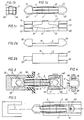
- the plug-in contact device shown in FIGS. 1a-1c consists of two elongated contact parts 1 and 2 and of an encompassing spring 3.
- the structure of the two contact parts, of which the contact part 1 is shown separately in FIGS. 2a and 2b, is identical.
- Each contact part 1, 2 consists of a flat, rectangular middle part 11 or 21 and two end sections which protrude from the plane of the middle part in the same direction and are designed as contact tongues.
- One end section consists of a center contact tongue 12 or 22, which lies in the middle of the narrow side of the middle part 11.
- the other end section consists of two side contact tongues 13, 14 and 23, 24, respectively, which are arranged on the sides of the narrow side of the middle part 11 and 21, respectively.
- the distance between the side contact tongues is greater than the thickness of the center contact tongues.
- the contact parts are expediently produced by cutting off a profile rod made of copper or another suitable contact material, the contact tongues being formed by subsequent milling of the ends. It is also possible to produce the contact parts directly in their final form by pressing or to produce them by sintering powdery material.
- the two contact parts 1 and 2 are placed one on top of the other with the opposite longitudinal orientation, so that the center contact tongue 12 of the contact part 1 lies between the side contact tongues 23, 24 of the contact part 2, and the center contact tongue 22 of the contact part 2 between the side contact tongues 13, 14 of the contact part 1 is located.
- the spring 3 is a substantially U-shaped leaf spring which engages around the contact parts, the legs of the spring being provided with spring arms 31, 32 (FIG. 1c) which extend in opposite directions in the longitudinal direction of the contact parts. This ensures that the contact points of the spring on the contact parts are close to the contact tongues, so that effective suspension is obtained at both ends of the contact device.
- the outwardly facing surfaces of the contact parts 1, 2 can be provided with embossments or recesses into which the ends of the spring arms 31, 32 engage.
- Figure 3 shows a contact device of the embodiment shown in Figures 1a-1c in the inserted position.
- the contact device is inserted into a longitudinal groove 41 of a device rail 4, which belongs to a pull-out device or a pull-out device group.
- the device rail is provided with locking edges 44 which are arranged so that the contact device can be pressed into the correct position, after which the locking edges hold the contact device in the rail.
- the two opposite groove walls 42, 43 form contact surfaces against which the contact tongues of one end section of the contact device bear under pressure by the spring 3.
- the other end section of the contact device rests under spring pressure against the two mutually opposite groove walls 52 and 53 of a groove 51 which belongs to the busbar 5 and has its opening in the direction of the rail 4.
- a busbar consisting of two parallel rails can be used.
- An insulating screen 55 provided with a slot 56 is arranged in front of the rail 5 as protection against contact.
- a major advantage of the contact device shown in Fig. 1a-1c c is that each contact part 1, 2 rests in three points on the contact surfaces of the rails 4, 5 (three-point system). This results in a good guidance of the contact parts in relation to each other and a good contact of the contacts in defined contact points, which u. a. contributes to the fact that the contact resistance is small.
- the short-circuit forces attempt to press the slot walls of the busbar (or the two rails when using a busbar consisting of two parallel rails), which could lead to permanent deformation of the contact device if another contact device is used.
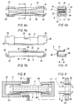
- Figure 4 shows how the one end portion of the contact device can be modified so that the contact device can be fixed in a device rail 45 which is provided with a rectangular hole 46, the dimensions of which are adapted to the cross-sectional dimension of the contact device.
- a device rail 45 which is provided with a rectangular hole 46, the dimensions of which are adapted to the cross-sectional dimension of the contact device.
- one has milled in the contact tongue 12 of the contact part 1 and in the contact tongues 23 and 24 transverse grooves 15 and 25 in such a way that the contact device engages in the hole 26 and can be held therein.
- FIG. 5 shows how the separation between a busbar 5 and a contact chamber 6 in a switchgear can be carried out with a contact device according to the invention.
- the contact tongues are provided at one end of the contact device with a through hole 61 in which a contact slide 62 is attached, the diameter or cross section of which is noticeably smaller than that of the hole 61. Due to their special structure, there is enough space for the contact device in the narrow space between the contacting surfaces of the contact chamber 6.
- FIGs 6a. and Figures 6b show another embodiment of a contact device according to the invention.
- This contact device consists of stamped and bent metal sheets, which means that their production costs are relatively low.
- the contact fingers of this contact device are not designed to form a contact system based on the three-point principle, and the support effect explained in the embodiment described above is not available.
- this simple embodiment of the contact device can be used to the full satisfaction in many applications in which no high demands are made.
- the contact device shown in FIGS. 6a and 6b consists of two contact parts 7 and 8 and two curved leaf springs 35 and 36.
- the contact parts are in engagement with one another and are connected to one another by means of the leaf springs, which also bring about the required contact pressure.
- the two contact parts. the contact part 7 of which is shown separately in FIGS. 7a-7c are exactly the same in their construction.
- Each contact part 7 and 8 has a flat rectangular base part 71 or 81 with a stiffening edge 72 or 82 running at right angles to the base part in the longitudinal direction.
- Each contact part has two contact tongues 73, 74 and 83, 84, respectively, which are attached to the ends of the contact part.
- the contact tongues are bent at right angles to the stiffening edge, so that the contact tongues lie essentially parallel to the plane of the base part.
- FIG. 8 shows a contact device of the embodiment shown in FIGS. 6a and 6b, which is fixed in a device rail 4 of a pull-out device provided with a longitudinal groove 41 and locking edges 44.
- the device with the contact device present on it is in contact with a busbar 5 which is fixedly mounted in the switchgear assembly and has opposite contact surfaces 52, 53, between which the contact device is inserted.
- FIG. 9 shows a modified embodiment of the one end section of the contact device according to FIGS. 6a and 6b.
- Can be in this execution run g sForm are pressed into the Kunststoffzun g s 74, 84 of the contact parts 7, 8, barrier strips 77, 78 and 87, 88, so that the Kontäktvorplatz snap into a rectangular hole in a mounting rail 45 and held therein .
- each contact part of the contact device shown in FIGS. 1a-1c c can also be produced by stamping and bending sheet metal.
- Each contact part consists of a flat, rectangular middle part and upright contact tongues lying perpendicular to the plane of the middle part.
- the middle contact tongue forming the end section is formed from two pressed metal strips.
- the contact parts are produced in that an elongated, essentially rectangular hole is punched into an elongated, essentially rectangular piece of sheet metal and then the contact part is shaped by bending such that its central part consists of two elongated, spaced apart and consists of arms lying side by side in different planes, while its end sections consist of essentially U-shaped contact brackets which connect the ends of the arms.
- the distance between the outer surfaces of the stirrup legs of the contact clip at one end section is made smaller than the distance between the inner surfaces of the contact clip at the other end section, so that the end sections of the two contact parts of the contact device fit together when the contact parts are placed against one another on opposite sides.
- the contact pressure spring can expediently be a wire spring which is arranged in the plane of symmetry of the contact device between the four arms of the two contact parts and which extends between the end sections of the contact device and is supported on the base parts of the contact bracket.
Landscapes
- Contacts (AREA)
- Coupling Device And Connection With Printed Circuit (AREA)
- Connections Arranged To Contact A Plurality Of Conductors (AREA)
- Auxiliary Devices For And Details Of Packaging Control (AREA)
- Details Of Connecting Devices For Male And Female Coupling (AREA)
Description
Die Erfindung betrifft eine Steckkontaktvorrichtung gemäß dem Oberbegriff des Anspruches 1. Eine solche Steckkontaktvorrichtung ist bekannt aus der US-A-4 227 596.The invention relates to a plug contact device according to the preamble of
Die Kontaktvorrichtung ist vor allem zum Anschluß solcher Geräte und Gerätegruppen in Niederspannungsschaltanlagen geeignet, die zur Herstellung bzw. Aufhebung des elektrischen Anschlusses einschiebbar bzw, herausziehbar ausgebildet sind.The contact device is particularly suitable for connecting such devices and device groups in low-voltage switchgear assemblies which are designed to be inserted or withdrawn in order to establish or remove the electrical connection.
Solche herausziehbaren Geräte müssen mit einer Steckkontaktvorrichtung (englisch : plug-in-Kontaktvorrichtung) zum Anschluß der Hauptstrompfade an die Sammelschienen der Schaltanlage versehen sein. Bei einem vollkommen berührungsgeschützten Sammelschienensystem sollen diese Steckkontaktvorrichtungen, um ein einfaches System zu erhalten, schmal sein, um durch Schlitze in einem vor den Sammelschienen angeordneten Isolierschirm hindurchgeführt werden zu können. Die Steckkontaktvorrichtungen sollen sehr zuverlässig sein, einen niedrigen Übergangswiderstand haben, eine nachführende Kontaktanlage haben und kurzschlußsicher sein.Such pull-out devices must be provided with a plug-in contact device for connecting the main current paths to the busbars of the switchgear. In a completely contact-protected busbar system, in order to obtain a simple system, these plug-in contact devices should be narrow so that they can be passed through slots in an insulating screen arranged in front of the busbars. The plug contact devices should be very reliable, have a low contact resistance, have a contact system and be short-circuit proof.
Bei der aus der US-A-4 227 596 bekannten Steckkontaktvorrichtung für herausziehbare Geräte sind zwei Kontaktteile vorhanden, die zwei elektrisch parallelgeschaltete Strompfade bilden zwischen einer Sammelschiene mit zwei einander gegenüberliegenden parallelen Kontaktflächen einerseits und einem Kontaktmesser an dem herausziehbaren Gerät andererseits. Die Strompfade kreuzen sich an dem einen Endabschnitt der Kontaktvorrichtung und verlaufen parallel in einem relativ langen mittleren Abschnitt der Kontaktvorrichtung, wodurch man eine elektrodynamische Kontaktdruckverstärkung erhält. Die Kontaktvorrichtung ist von einem isolierenden Geha- üse umgeben, das beispielsweise in einem Schaltschrank fest montiert ist, wobei sich das eine Ende der Kontaktvorrichtung in ständiger Verbindung mit der Sammelschiene befindet. Eine solche Ausführung hat u.a. den Nachteil, daß die Kontaktvorrichtung für Kontrollzwecke schwer zugänglich ist, da sie im Schaltschrank eingeschlossen und dort fest montiert ist. Da es in der Regel die beweglichen Teile einer Vorrichtung sind, die der Wartung bedürfen, ist man bestrebt,' so wenig wie möglich bewegliche Teile fest im Schaltschrank zu montieren. Außerdem wird die Kontaktvorrichtung durch das isolierende Gehäuse verteuert.In the plug-in contact device for pull-out devices known from US-A-4 227 596 there are two contact parts which form two electrically parallel current paths between a busbar with two mutually opposite parallel contact surfaces on the one hand and a contact knife on the pull-out device on the other hand. The current paths intersect at one end section of the contact device and run parallel in a relatively long central section of the contact device, as a result of which an electrodynamic contact pressure gain is obtained. The contact device is surrounded by an insulating housing which is fixedly mounted, for example, in a control cabinet, one end of the contact device being in permanent connection with the busbar. Such a design has i.a. the disadvantage that the contact device is difficult to access for control purposes, since it is enclosed in the control cabinet and fixed there. Since it is usually the moving parts of a device that require maintenance, efforts are made to 'mount as few moving parts as possible firmly in the control cabinet. In addition, the contact device is made more expensive by the insulating housing.
Der Erfindung liegt die Aufgabe zugrunde, eine Steckkontaktvorrichtung der eingangs genannten Art zu entwickeln, die im Vergleich zu den bekannten Steckvorrichtungen einfacher, zuverlässiger, billiger und leichter zu kontrollieren und zu warten ist.The invention has for its object to develop a plug contact device of the type mentioned, which is simpler, more reliable, cheaper and easier to control and maintain compared to the known plug devices.
Zur Lösung dieser Aufgabe wird eine Steckkontaktvorrichtung nach dem Oberbegriff des Anspruches 1 und 2 vorgeschlagen, die erfindungsgemäß die im kennzeichnenden Teil des Anspruches 1 bzw. 2 genannten Merkmale hat.To solve this problem, a plug contact device according to the preamble of
Vorteilhafte Weiterbildungen der Erfindung sind in den Unteransprüchen genannt.Advantageous developments of the invention are mentioned in the subclaims.
Eine Kontaktvorrichtung gemäß der Etfindung läßt sich ohne Hilfsmittel leicht an dem herausziehbaren Gerät anbringen, und da die Kontaktvorrichtung dem Gerät folgt, braucht sie nicht von einem isolierenden Gehäuse umgeben zu sein. Sie kann leicht kontrolliert werden, ohne daß die Schaltanlge spannungsfrei geschaltet zu . werden braucht. Bei der Kontaktvorrichtung gemäß der Erfindung sind beide Endabschnitte so ausgebildet, daß sich die beiden Strompfade in den Endabschnitten kreuzen. Die langen Mittelteile der beiden Kontaktteile verlaufen verhältnismäßig nahe beieinander.A contact device according to the invention can be easily attached to the pull-out device without tools, and since the contact device follows the device, it need not be surrounded by an insulating housing. It can be easily checked without the switchgear being switched off. are needed. In the contact device according to the invention, both end sections are designed such that the two current paths intersect in the end sections. The long middle parts of the two contact parts run relatively close to each other.
Um eine gute Führung und ein gutes Anliegen der Kontakte zu erhalten, sind die Kontaktteile so ausgebildet, daß jedes Kontaktteil in je drei Punkten an den beiden Kontaktschienen anliegt, die es miteinander verbindet. Dadurch wird die Kontakvorrichtung gegenüber einer Drehung verhältnismäßig unempfindlich.In order to obtain a good guidance and a good contact of the contacts, the contact parts are designed so that each contact part rests in three points on the two contact rails that it connects. This makes the contact device relatively insensitive to rotation.
Anhand der in den Figuren gezeigten Ausführungsbeispiele soll die Erfindung näher erläutert werden. Es zeigen
- Fig. 1a eine erste Ausführungsform einer Kontaktvorrichtung gemäß der Erfindung in Seitenansicht,
- Fig. 1b die Kontaktvorrichtung gemäß Fig. 1a in Endansicht,
- Fig. 1c die Kontaktvorrichtung nach Fig. 1 von oben,
- Fig. 2a und 2b ein Kontaktteil der Kontaktvorrichtung nach Fig. 1a-1c in Seitenansicht und Draufsicht,
- Fig. 3 eine Kontaktvorrichtung nach Fig. 1a-1c - in ihrer Betriebsstellung zwischen einer Sammelschiene und einer Geräteschiene,
- Fig. 4 in Seitenansicht den Endabschnitt einer abgewandelten Ausführung einer Kontaktvorrichtung nach Fig. 1a-1c, der in einer Geräteschiene befestigt ist,
- Fig. 5 eine Kontaktvorrichtung nach Fig. 1a-1c, die als Trennschalter zwischen einer Sammelschiene und einer fest montierten Kontaktkammer verwendet wird.
- Fig. 6a eine zweite Ausführungsform einer Kontaktvorrichtung gemäß der Erfindung in Seitenansicht,
- Fig. 6b die Ausführungsform nach Fig. 6a längs eines Schnittes A-A in Fig. 6a,
- Fig. 7a, 7b und 7c eines der Kontaktteile der Kontaktvorrichtung nach Fig. 6a und 6b in Seitenansicht, Draufsicht und im Schnitt längs der Linie B-B,
- Fig. 8 die Kontaktvorrichtung nach Fig. 6a und 6b in ihrer Betriebsstellung zwischen einer Sammelschiene und einer Geräteschiene,
- Fig. 9 in Seitenansicht den Endabschnitt einer abgewandelten Ausführungsform der Kontaktvorrichtung nach Fig. 6a und 6b, der in einer Geräteschiene befestigt ist.
- 1a shows a first embodiment of a contact device according to the invention in side view,
- 1b, the contact device according to FIG. 1a in end view,
- 1c the contact device of FIG. 1 from above,
- 2a and 2b, a contact part of the contact device according to Fig. 1a-1c in side view and plan view,
- 3 shows a contact device according to FIGS. 1a-1c - in its operating position between a busbar and a device rail,
- 4 shows a side view of the end section of a modified embodiment of a contact device according to FIGS. 1a-1c, which is fastened in a device rail,
- Fig. 5 shows a contact device according to Fig. 1a-1c, which is used as a disconnector between a busbar and a fixedly mounted contact chamber.
- 6a shows a second embodiment of a contact device according to the invention in side view,
- 6b shows the embodiment of FIG. 6a along a section AA in Fig. 6a,
- 7a, 7b and 7c one of the contact parts of the contact device according to Fig. 6a and 6b in side view, top view and in section along the line BB,
- 8 shows the contact device according to FIGS. 6a and 6b in its operating position between a busbar and a device rail,
- Fig. 9 in side view of the end portion of a modified embodiment of the contact device according to Fig. 6a and 6b, in one device rail is attached.
Die in den Figuren 1a-1c gezeigte Steckkontaktvorrichtung besteht aus zwei länglichen Kontaktteilen 1 und 2 sowie aus einer umgreifenden Feder 3. Der Aufbau der beiden Kontaktteile, von denen das Kontaktteil 1 separat in den Figuren 2a und 2b gezeigt ist, ist identisch. Jedes Kontaktteil 1, 2 besteht aus einem ebenen, rechteckigen Mittelteil 11 bzw. 21 und zwei aus der Ebene des Mittelteils in derselben Richtung herausragenden, als Kontaktzungen ausgebildeten Endabschnitten. Der eine Endabschnitt besteht aus einer Mittelkontaktzunge 12 bzw. 22, die in der Mitte der schmalen Seite des Mittelteils 11 liegt. Der andere Endabschnitt besteht aus zwei Seitenkontaktzungen 13, 14 bzw. 23, 24, die an den Seiten der schmalen Seite des Mittelteils 11 bzw. 21 angeordnet sind. Der Abstand zwischen den Seitenkontaktzungen ist größer als die Dicke der Mittelkontaktzungen.The plug-in contact device shown in FIGS. 1a-1c consists of two
Die Kontaktteile werden zweckmäßig durch Abschneiden von einer Profilstange aus Kupfer oder einem anderen geeigneten Kontaktmaterial hergestellt, wobei durch anschließendes Einfräsen der Enden die Kontaktzungen gebildet werden. Es ist auch möglich, die Kontaktteile durch Pressen unmittelbar in ihrer endgültigen Form herzustellen oder sie durch Sinterung pulverförmigen Materials herzustellen.The contact parts are expediently produced by cutting off a profile rod made of copper or another suitable contact material, the contact tongues being formed by subsequent milling of the ends. It is also possible to produce the contact parts directly in their final form by pressing or to produce them by sintering powdery material.
Wie die Figuren 1a-1c zeigen, sind die beiden Kontaktteile 1 und 2 mit entgegengesetzt gerichteter Längsorientierung aufeinandergelegt, so daß die Mittelkontaktzunge 12 des Kontaktteils 1 zwischen den Seitenkontaktzungen 23, 24 des Kontaktteils 2 liegt, und die Mittelkontaktzunge 22 des Kontaktteils 2 zwischen den Seitenkontaktzungen 13, 14 des Kontaktteils 1 liegt.As shown in FIGS. 1a-1c, the two
Die Feder 3 ist eine im wesentlichen U-förmig gebogene Blattfeder, welche die Kontaktteile umgreift, wobei die Schenkel der Feder mit Federarmen 31, 32 (Fig. 1c) versehen sind, die sich in entgegengesetzten Richtungen in Längsrichtung der Kontaktteile erstrecken. Hierdurch wird erreicht, daß die Anlagepunkte der Feder an den Kontaktteilen nahe bei den Kontaktzungen liegen, so daß man an beiden Enden der Kontaktvorrichtung eine wirksame Federung erhält. Zur Fixierung der Feder kann man die nach außen gerichteten Flächen der Kontaktteile 1, 2 mit Prägungen oder Aussparungen versehen, in welche die Enden der Federarme 31, 32 eingreifen.The
Figur 3 zeigt eine Kontaktvorrichtung der in den Figuren 1a-1c gezeigten Ausführung in eingesetzter Stellung. Die Kontaktvorrichtung ist in eine Längsnut 41 einer Geräteschiene 4 eingesetzt, die zu einem herausziehbaren Gerät oder einer herausziehbaren Gerätegruppe gehört. Die Geräteschiene ist mit Sperrkanten 44 versehen, die so angeordnet sind, daß die Kontaktvorrichtung in die richtige Lage gedrückt werden kann, wonach die Sperrkanten die Kontaktvorrichtung in der Schiene festhalten. Die beiden gegenüberliegenden Nutwände 42, 43 bilden Kontaktflächen, an welchen die Kontaktzungen des einen Endabschnittes der Kontaktvorrichtung unter Druck durch die Feder 3 anliegen. Der andere Endabschnitt der Kontaktvorrichtung liegt unter Federdruck an die beiden einander gegenüberliegenden Nutwände 52 und 53 einer Nut 51 an, die zur Sammelschiene 5 gehört und in Richtung zur Schiene 4 ihre Öffnung hat. Statt einer solchen Schiene mit Nut kann eine aus zwei parallelen Schienen bestehende Sammelschiene verwendet werden. Vor der Schiene 5 ist als Berührungsschutz ein mit einen Schlitz 56 versehener Isolierschirm 55 angeordnet. Durch die beiden Kontaktteile der Kontaktvorrichtung werden zwei elektrisch parallelgeschaltete Strompfade 11 und 12 zwischen den beiden Schienen 5 und 4 hergestellt. Diese Strompfade kreuzen sich an den beiden Endabschnitten der Kontaktvorrichtung, während sie auf einer verhältnismäßig langen Strecke zwischen den Kreuzungsstellen im wesentlichen parallel verlaufen und verhältnismäßig dicht beieinanderliegen. Zwischen den parallelen Strompfade tritt bei einem Kurzschlußstrom eine starke Anziehungskraft auf, wodurch der Kontaktdruck verstärkt wird. Die Kontaktvorrichtung ist daher kurzschlußsicher.Figure 3 shows a contact device of the embodiment shown in Figures 1a-1c in the inserted position. The contact device is inserted into a
Ein wesentlicher Vorteil der in Fig. 1a-1c c gezeigten Kontaktvorrichtung besteht darin, daß jedes Kontaktteil 1, 2 in drei Punkten an den Kontaktflächen der Schienen 4, 5 anliegt (Dreipunktanlage). Dadurch erzielt man eine gute Führung der Kontaktteile im Verhältnis zueinander sowie eine gute Anlage der Kontakte in definierten Kontaktpunkten, was u. a. dazu beiträgt, daß der Übergangswiderstand klein ist. Dadurch, daß die Kontaktzungen massiv ausgebildet sind, und ihre Abmessungen so bemessen sind, daß sie nur etwas schmaler als die Nut 51 der Sammelschiene 5 sind, erhält man außerdem eine Stützwirkung an der Sammelschiene, die z. B. während eines Kurzschlusses sehr vorteilhaft ist. Bei einem Kurzschluß versuchen die Kurzschlußkräfte die Nutenwände der Sammelschiene (bzw. die beiden Schienen bei Verwendung einer aus zwei parallelen Schienen bestehenden Sammelschiene) gegeneinanderzudrücken, was bei Verwendung einer anderen Kontaktvorrichtung zu einer bleibenden Verformung der Kontaktvorrichtung führen könnte.A major advantage of the contact device shown in Fig. 1a-1c c is that each
Figur 4 zeigt, wie der eine Endabschnitt der Kontaktvorrichtung so modifiziert werden kann, daß die Kontaktvorrichtung in einer Geräteschiene 45 festgesetzt werden kann, die mit einem rechteckigen Loch 46 versehen ist, dessen Abmessungen dem Querschnittsmaß der Kontaktvorrichtung angepaßt sind. Bei dieser Ausführung hat man in die Kontaktzunge 12 des Kontaktteils 1 sowie in die Kontaktzungen 23 und 24 Quernuten 15 bzw. 25 auf solche Weise eingefräst, daß die Kontaktvorrichtung in das Loch 26 einrastet und darin festgehalten werden kann.Figure 4 shows how the one end portion of the contact device can be modified so that the contact device can be fixed in a
Figur 5 zeigt, wie man mit einer Kontaktvorrichtung nach der Erfindung die Trennung zwischen einer Sammelschiene 5 und einer Kontaktkammer 6 in einer Schaltanlage vornehmen kann. In diesem Fall sind die Kontaktzungen an dem einen Ende der Kontaktvorrichtung mit einem durchgehenden Loch 61 versehen, in dem ein Kontaktschieber 62 befestigt ist, dessen Durchmesser bzw. Querschnitt merklich kleiner als der des Loches 61 ist. Durch ihren speziellen Aufbau ist für die Kontaktvorrichtung genügend Platz in dem schmalen Raum zwischen den kontaktgebenden Flächen der Kontaktkammer 6 vorhanden.FIG. 5 shows how the separation between a
Die Figuren 6a. und 6b zeigen eine andere Ausführungsform einer Kontaktvorrichtung nach der Erfindung. Diese Kontaktvorrichtung besteht aus gestanzten und gebogenen Blechen, wodurch ihre Herstellungskosten verhältnismäßig gering sind. Die Kontaktfinger dieser Kontaktvorrichtung sind nicht zu einer Kontaktanlage nach dem Dreipunktprinzip ausgebildet, und die bei der oben beschriebenen Ausführungsform erläuterte Stützwirkung ist nicht vorhanden. Diese einfache Ausführungsform der Kontaktvorrichtung kann jedoch zur vollen Zufriedenheit in vielen Anwendungsfällen eingesetzt werden, bei denen keine hohen Ansprüche gestellt werden.Figures 6a. and Figures 6b show another embodiment of a contact device according to the invention. This contact device consists of stamped and bent metal sheets, which means that their production costs are relatively low. The contact fingers of this contact device are not designed to form a contact system based on the three-point principle, and the support effect explained in the embodiment described above is not available. However, this simple embodiment of the contact device can be used to the full satisfaction in many applications in which no high demands are made.
Die in den Figuren 6a und 6b gezeigte Kontaktvorrichtung besteht aus zwei Kontaktteilen 7 und 8 sowie zwei gebogenen Blattfedern 35 und 36. Die Kontaktteile liegen in Eingriff miteinander und sind mit Hilfe der Blattfedern, die außerdem den erforderlichen Kontaktdruck bewirken, miteinander verbunden. Die beiden Kontaktteile. von denen das Kontaktteil 7 separat in Fig.7a-7c gezeigt ist, sind in ihrem Aufbau genau gleich. Zu jedem Kontaktteil 7 und 8 gehört ein ebenes rechteckiges Grundteil 71 bzw. 81 mit einer im rechten Winkel zum Grundteil in Längsrichtung verlaufenden Versteifungskante 72 bzw. 82.The contact device shown in FIGS. 6a and 6b consists of two
Jedes Kontaktteil hat zwei Kontaktzungen 73, 74 bzw. 83, 84, die an den Enden des Kontaktteils angebracht sind. Die Kontaktzungen sind im rechten Winkel zur Versteifungskante abgebogen, so daß die Kontaktzungen im wesentlichen parallel zur Ebene des Grundteils liegen.Each contact part has two
In der Mitte der freien Längskante des Grundteils sowie an der Kante der Kontaktzungen sind Erhöhungen 75, 85 bzw. 76, 86 zur Fixierung der Blattfedern 35, 36 in das Blech gepreßt. Durch die gezeigte Ausführung erreicht man in einfacher Weise, daß die einzelnen zu der Kontaktvorrichtung gehörenden Teile miteinander verbunden werden.In the middle of the free longitudinal edge of the base part and on the edge of the contact tongues are raised 75, 85 and 76, 86 for fixing the
Figur 8 zeigt eine Kontaktvorrichtung der in den Figuren 6a und 6b gezeigten Ausführungsform, die in einer mit einer Längsnut 41 und Sperrkanten 44 versehenen Geräteschiene 4 eines herausziehbaren Gerätes fixiert ist. Das Gerät mit der an ihm vorhandenen Kontaktvorrichtung steht in Kontakt mit einer in der Schaltanlage fest montierten Sammelschiene 5, die einander gegenüberliegende Kontaktflächen 52, 53 hat, zwischen denen die Kontaktvorrichtung eingeschoben ist.FIG. 8 shows a contact device of the embodiment shown in FIGS. 6a and 6b, which is fixed in a
Figur 9 zeigt eine modifizierte Ausführungsform des einen Endabschnittes der Kontaktvorrichtung nach den Figuren 6a und 6b. Bei dieser Ausfüh- rungsform sind in die Kontaktzungen 74, 84 der Kontaktteile 7, 8 Sperrstreifen 77, 78 bzw. 87, 88 gepreßt, so daß die Kontäktvorrichtung in einem rechteckigen Loch in einer Geräteschiene 45 einrasten und darin festgehalten werden kann.FIG. 9 shows a modified embodiment of the one end section of the contact device according to FIGS. 6a and 6b. Can be in this execution run g sForm are pressed into the Kontaktzun g s 74, 84 of the
.Beispielsweise können auch die Kontaktteile der in den Figuren 1a-1c c dargestellten Kontaktvorrichtung durch Stanzen und Biegen von Blech hergestellt werden. Jedes Kontaktteil besteht dabei aus einem ebenen, rechteckigen Mittelteil und senkrecht zur Ebene des Mittelteils liegende, hochgebogene Kontaktzungen. Die den einen Endabschnitt bildende Mittelkontaktzunge wird dabei aus zwei aneinandergepreßten Blechstreifen gebildet.For example, the contact parts of the contact device shown in FIGS. 1a-1c c can also be produced by stamping and bending sheet metal. Each contact part consists of a flat, rectangular middle part and upright contact tongues lying perpendicular to the plane of the middle part. The middle contact tongue forming the end section is formed from two pressed metal strips.
Gemäß einer anderen denkbaren Ausführungsform werden die Kontaktteile dadurch hergestellt, daß in ein längliches, im wesentlichen rechteckiges Blechstück ein längliches, im wesentlichen rechteckiges Loch gestanzt wird und danach das Kontaktteil durch Biegen so geformt wird, daß sein Mittelteil aus zwei langgestreckten, in Abstand voneinander und in verschiedenen Ebenen nebeneinander liegenden Armen besteht, während seine Endabschnitte aus im wesentlichen U-förmigen Kontaktbügeln bestehen, welche die Enden der Arme verbinden. Der Abstand zwischen den Außenflächen der Bügelschenkel des Kontaktbügels an dem einen Endabschnitt wird kleiner gemacht als der Abstand zwischen den Innenflächen des Kontaktbügels an dem anderen Endabschnitt, so daß die Endabschnitte der zwei Kontaktteile der Kontaktvorrichtung zusammenpassen, wenn die Kontaktteile mit entgegengesetzten Seiten zueinander aneinandergelegt werden. Die Kontaktdruckfeder kann in diesem Fall zweckmäßig eine Drahtfeder sein, die in der Symmetrieebene der Kontaktvorrichtung zwischen den vier Armen der beiden Kontaktteile angeordnet ist und die sich zwischen den Endabschnitten der Kontaktvorrichtung erstreckt und sich an den Grundteilen der Kontaktbügel abstützt.According to another conceivable embodiment, the contact parts are produced in that an elongated, essentially rectangular hole is punched into an elongated, essentially rectangular piece of sheet metal and then the contact part is shaped by bending such that its central part consists of two elongated, spaced apart and consists of arms lying side by side in different planes, while its end sections consist of essentially U-shaped contact brackets which connect the ends of the arms. The distance between the outer surfaces of the stirrup legs of the contact clip at one end section is made smaller than the distance between the inner surfaces of the contact clip at the other end section, so that the end sections of the two contact parts of the contact device fit together when the contact parts are placed against one another on opposite sides. In this case, the contact pressure spring can expediently be a wire spring which is arranged in the plane of symmetry of the contact device between the four arms of the two contact parts and which extends between the end sections of the contact device and is supported on the base parts of the contact bracket.
Es können mehrere Kontaktvorrichtungen der beschriebenen Ausführungsformen parallel angeordnet werden, um eine Anpassung an verschiedene Nennströme zu erreichen.Several contact devices of the described embodiments can be arranged in parallel in order to adapt to different nominal currents.
Claims (8)
Applications Claiming Priority (2)
| Application Number | Priority Date | Filing Date | Title |
|---|---|---|---|
| SE8107767 | 1981-12-23 | ||
| SE8107767A SE429178B (en) | 1981-12-23 | 1981-12-23 | PLUG CONNECTOR |
Publications (3)
| Publication Number | Publication Date |
|---|---|
| EP0086316A2 EP0086316A2 (en) | 1983-08-24 |
| EP0086316A3 EP0086316A3 (en) | 1986-05-21 |
| EP0086316B1 true EP0086316B1 (en) | 1988-07-06 |
Family
ID=20345364
Family Applications (1)
| Application Number | Title | Priority Date | Filing Date |
|---|---|---|---|
| EP82710058A Expired EP0086316B1 (en) | 1981-12-23 | 1982-12-11 | Plug-in contact device for the establishment of an electrical connection between two bus-bars |
Country Status (7)
| Country | Link |
|---|---|
| US (1) | US4596438A (en) |
| EP (1) | EP0086316B1 (en) |
| DE (1) | DE3278749D1 (en) |
| DK (1) | DK562882A (en) |
| FI (1) | FI69728C (en) |
| NO (1) | NO158559C (en) |
| SE (1) | SE429178B (en) |
Cited By (2)
| Publication number | Priority date | Publication date | Assignee | Title |
|---|---|---|---|---|
| DE4127708A1 (en) * | 1991-08-20 | 1993-02-25 | Siemens Ag | DISCONNECTING ARRANGEMENT FOR A SLIDING DEVICE CARRIER |
| DE4414917A1 (en) * | 1993-04-30 | 1994-11-17 | Sotax Ag | Contact device for the electrical connection of conductors |
Families Citing this family (10)
| Publication number | Priority date | Publication date | Assignee | Title |
|---|---|---|---|---|
| US4662706A (en) * | 1985-04-25 | 1987-05-05 | Elcon Products International Company | Electrical device |
| DE4013311A1 (en) * | 1990-04-26 | 1991-10-31 | Kloeckner Moeller Gmbh | CONNECTING ELEMENT FOR THE ELECTRICAL CONNECTION, ESPECIALLY IN DISTRIBUTION SYSTEMS OR THE LIKE |
| DE4034204C2 (en) * | 1990-10-27 | 2002-04-18 | Wago Verwaltungs Gmbh | Electrical terminal with busbar connection |
| SE501134C2 (en) * | 1992-12-22 | 1994-11-21 | Asea Brown Boveri | Catch contact device and use thereof for extensible high voltage apparatus |
| DE9309403U1 (en) * | 1993-06-24 | 1993-09-16 | Esselbrügge, Peter, 63075 Offenbach | Device for arranging and operating electrical functional elements |
| GB2288078A (en) * | 1994-03-11 | 1995-10-04 | Horstmann Timers & Controls | Electrical connectors |
| DE19816507A1 (en) * | 1998-04-14 | 1999-10-21 | Asea Brown Boveri | Burn-up switching arrangement |
| DE502004011428D1 (en) * | 2004-12-21 | 2010-09-02 | Abb Technology Ag | Contact system for an electrical switching device |
| US10985487B2 (en) * | 2019-07-15 | 2021-04-20 | Abb Schweiz Ag | Electrical connector between a bus and a circuit breaker |
| US11651921B2 (en) * | 2020-05-06 | 2023-05-16 | Abb Schweiz Ag | Electrical connector with non-linear spring force |
Family Cites Families (12)
| Publication number | Priority date | Publication date | Assignee | Title |
|---|---|---|---|---|
| FR840456A (en) * | 1937-07-08 | 1939-04-26 | Fides | electrical contact element for connecting two or more sockets located one behind the other and the bores of which have the same axis |
| US2872659A (en) * | 1953-10-30 | 1959-02-03 | Electric Products Company | Contact assembly |
| FR1148312A (en) * | 1956-05-02 | 1957-12-06 | Ch Milde Fils & Cie | Busbar connector |
| US3031642A (en) * | 1960-05-11 | 1962-04-24 | Jr Charles E Gartner | Safety test clip |
| GB1331252A (en) * | 1970-01-10 | 1973-09-26 | Lucas Industries Ltd | Pins for electrical connectors |
| DE2165940C2 (en) * | 1971-12-30 | 1982-05-06 | Siemens AG, 1000 Berlin und 8000 München | Contact device for LV load switch - has cage surrounding contact plates and press springs held in reception aperture via further springs |
| NL150627B (en) * | 1972-10-18 | 1976-08-16 | Amp Inc | ELECTRICAL CONNECTION DEVICE WITH AN EQUIPPED PICK-UP CONTACT AND AN INSERTION CONTACT WITH WIDE-HEAD TO BE INSERTED IN THIS PLACE, WHERE THE PLUG-IN CONTACT WITH A NARROWED PART CAN BE TIGHTENED FREELY IN THE TAKING-UP CONTACT AND TIGHTENED AFTER TIGHTENING. |
| US3821691A (en) * | 1973-09-24 | 1974-06-28 | Gte Automatic Electric Lab Inc | Wire terminal |
| US3995931A (en) * | 1975-03-26 | 1976-12-07 | Molex Incorporated | Terminal for apertured circuit panel |
| NL165339C (en) * | 1977-06-08 | 1981-03-16 | Hazemeijer Bv | CONTACT DEVICE. |
| GB2013422B (en) * | 1978-01-25 | 1982-09-08 | Bicc Ltd | Electric couplers |
| FR2432777A1 (en) * | 1978-07-31 | 1980-02-29 | Telemecanique Electrique | CONNECTION DEVICE FOR THE END OF AN OMNIBUS BARS ARRANGED IN A SHEATH |
-
1981
- 1981-12-23 SE SE8107767A patent/SE429178B/en not_active IP Right Cessation
-
1982
- 1982-12-11 EP EP82710058A patent/EP0086316B1/en not_active Expired
- 1982-12-11 DE DE8282710058T patent/DE3278749D1/en not_active Expired
- 1982-12-20 DK DK562882A patent/DK562882A/en not_active Application Discontinuation
- 1982-12-21 FI FI824402A patent/FI69728C/en not_active IP Right Cessation
- 1982-12-21 NO NO824299A patent/NO158559C/en unknown
-
1985
- 1985-04-04 US US06/719,049 patent/US4596438A/en not_active Expired - Fee Related
Cited By (2)
| Publication number | Priority date | Publication date | Assignee | Title |
|---|---|---|---|---|
| DE4127708A1 (en) * | 1991-08-20 | 1993-02-25 | Siemens Ag | DISCONNECTING ARRANGEMENT FOR A SLIDING DEVICE CARRIER |
| DE4414917A1 (en) * | 1993-04-30 | 1994-11-17 | Sotax Ag | Contact device for the electrical connection of conductors |
Also Published As
| Publication number | Publication date |
|---|---|
| NO824299L (en) | 1983-06-24 |
| SE8107767L (en) | 1983-06-24 |
| SE429178B (en) | 1983-08-15 |
| DE3278749D1 (en) | 1988-08-11 |
| FI824402L (en) | 1983-06-24 |
| FI69728B (en) | 1985-11-29 |
| NO158559B (en) | 1988-06-20 |
| FI69728C (en) | 1986-03-10 |
| US4596438A (en) | 1986-06-24 |
| EP0086316A2 (en) | 1983-08-24 |
| NO158559C (en) | 1988-09-28 |
| DK562882A (en) | 1983-06-24 |
| EP0086316A3 (en) | 1986-05-21 |
| FI824402A0 (en) | 1982-12-21 |
Similar Documents
| Publication | Publication Date | Title |
|---|---|---|
| EP0554519B1 (en) | Grounding terminal | |
| EP0634888B1 (en) | Plug-in unit, particularly relay module for motor vehicles | |
| DE2639642C2 (en) | Electrical connection contact arrangement with clamping contact pieces | |
| EP0107611B1 (en) | Contact disconnecting device with bridging contact blades for pull-out switch-gears | |
| EP0735628A2 (en) | Bus bar with terminal pin | |
| EP0086316B1 (en) | Plug-in contact device for the establishment of an electrical connection between two bus-bars | |
| DE69515128T2 (en) | CONNECTING TERMINAL ON BUSBARS FOR SWITCH SWITCHES OR MULTIPOLE DISCONNECTABLE SYSTEMS | |
| DE68913843T2 (en) | Electrical connector with a solder. | |
| DE4323426A1 (en) | Contact pliers | |
| DE102009030645B4 (en) | Brückerelement and set of at least one clamping element and Brückerelement | |
| EP0636281B1 (en) | Multipole connector insert | |
| DE3232679C2 (en) | Electromagnetic switching relay for high current loads | |
| DE69303065T2 (en) | Connector clamp with saddle of variable thickness and with a bordered nut | |
| EP0223732B1 (en) | Multipole low-voltage power circuit breaker with current bars | |
| EP1587166B1 (en) | Repartition block | |
| WO2002027740A1 (en) | Displaceable contact support for a low-voltage power switch with a separator for the contact levers | |
| DE2021455C3 (en) | Monostable electromagnetic miniature relay | |
| EP0258664A2 (en) | Unit for securing electrical lines in distributors of telecommunication installations | |
| EP0863577B1 (en) | Protective wire connection for motor | |
| DE809827C (en) | Electrical plug contact device | |
| EP0901186A2 (en) | Connecting terminal for shielded cables | |
| WO1998009307A1 (en) | Mobile switching contact arrangement with contact force springs | |
| DE69305147T2 (en) | Contact device | |
| DE3202580C2 (en) | Relay with bridge contact arrangement and method for their manufacture | |
| DE3109011C2 (en) |
Legal Events
| Date | Code | Title | Description |
|---|---|---|---|
| PUAI | Public reference made under article 153(3) epc to a published international application that has entered the european phase |
Free format text: ORIGINAL CODE: 0009012 |
|
| PUAI | Public reference made under article 153(3) epc to a published international application that has entered the european phase |
Free format text: ORIGINAL CODE: 0009012 |
|
| AK | Designated contracting states |
Designated state(s): BE DE GB NL |
|
| PUAL | Search report despatched |
Free format text: ORIGINAL CODE: 0009013 |
|
| AK | Designated contracting states |
Kind code of ref document: A3 Designated state(s): BE DE GB NL |
|
| 17P | Request for examination filed |
Effective date: 19860911 |
|
| 17Q | First examination report despatched |
Effective date: 19870227 |
|
| GRAA | (expected) grant |
Free format text: ORIGINAL CODE: 0009210 |
|
| AK | Designated contracting states |
Kind code of ref document: B1 Designated state(s): BE DE GB NL |
|
| REF | Corresponds to: |
Ref document number: 3278749 Country of ref document: DE Date of ref document: 19880811 |
|
| GBT | Gb: translation of ep patent filed (gb section 77(6)(a)/1977) | ||
| PLBE | No opposition filed within time limit |
Free format text: ORIGINAL CODE: 0009261 |
|
| STAA | Information on the status of an ep patent application or granted ep patent |
Free format text: STATUS: NO OPPOSITION FILED WITHIN TIME LIMIT |
|
| 26N | No opposition filed | ||
| PGFP | Annual fee paid to national office [announced via postgrant information from national office to epo] |
Ref country code: BE Payment date: 19891103 Year of fee payment: 8 |
|
| PGFP | Annual fee paid to national office [announced via postgrant information from national office to epo] |
Ref country code: DE Payment date: 19891227 Year of fee payment: 8 |
|
| PGFP | Annual fee paid to national office [announced via postgrant information from national office to epo] |
Ref country code: NL Payment date: 19891231 Year of fee payment: 8 Ref country code: GB Payment date: 19891231 Year of fee payment: 8 |
|
| PG25 | Lapsed in a contracting state [announced via postgrant information from national office to epo] |
Ref country code: GB Effective date: 19901211 |
|
| PG25 | Lapsed in a contracting state [announced via postgrant information from national office to epo] |
Ref country code: BE Effective date: 19901231 |
|
| BERE | Be: lapsed |
Owner name: ASEA A.B. Effective date: 19901231 |
|
| PG25 | Lapsed in a contracting state [announced via postgrant information from national office to epo] |
Ref country code: NL Effective date: 19910701 |
|
| GBPC | Gb: european patent ceased through non-payment of renewal fee | ||
| NLV4 | Nl: lapsed or anulled due to non-payment of the annual fee | ||
| PG25 | Lapsed in a contracting state [announced via postgrant information from national office to epo] |
Ref country code: DE Effective date: 19910903 |