EP0901186A2 - Connecting terminal for shielded cables - Google Patents
Connecting terminal for shielded cables Download PDFInfo
- Publication number
- EP0901186A2 EP0901186A2 EP98115204A EP98115204A EP0901186A2 EP 0901186 A2 EP0901186 A2 EP 0901186A2 EP 98115204 A EP98115204 A EP 98115204A EP 98115204 A EP98115204 A EP 98115204A EP 0901186 A2 EP0901186 A2 EP 0901186A2
- Authority
- EP
- European Patent Office
- Prior art keywords
- connection element
- piece
- element according
- pressure pieces
- pressure
- Prior art date
- Legal status (The legal status is an assumption and is not a legal conclusion. Google has not performed a legal analysis and makes no representation as to the accuracy of the status listed.)
- Granted
Links
Images

Classifications
-
- H—ELECTRICITY
- H01—ELECTRIC ELEMENTS
- H01R—ELECTRICALLY-CONDUCTIVE CONNECTIONS; STRUCTURAL ASSOCIATIONS OF A PLURALITY OF MUTUALLY-INSULATED ELECTRICAL CONNECTING ELEMENTS; COUPLING DEVICES; CURRENT COLLECTORS
- H01R9/00—Structural associations of a plurality of mutually-insulated electrical connecting elements, e.g. terminal strips or terminal blocks; Terminals or binding posts mounted upon a base or in a case; Bases therefor
- H01R9/03—Connectors arranged to contact a plurality of the conductors of a multiconductor cable, e.g. tapping connections
- H01R9/05—Connectors arranged to contact a plurality of the conductors of a multiconductor cable, e.g. tapping connections for coaxial cables
- H01R9/0527—Connection to outer conductor by action of a resilient member, e.g. spring
Abstract
Description
Die Erfindung betrifft ein Anschlußelement für Schirmkabel. Derartige Anschlußelemente sind in ihrem grundsätzlichen Aufbau bekannt und weisen beispielsweise ein Schienenstück mit einem Halteelement für das Schirmkabel auf und ein verschieblich an dem Schienenstück geführten und unter Federspannung stehenden Druckstück, mit dem das Schirmgeflecht des Kabels nach Entfernen der Kabelisolierung an das Halteelement angedrückt wird (DE 195 37 585 C1). Das Anschlußelement ist elektrisch leitend mit irgendeinem PE-Anschluß einer Schaltanlage zu verbinden.The invention relates to a connection element for shield cables. Such Connection elements are known in their basic structure and have for example a rail piece with a holding element for the shield cable on and a slidably guided on the rail piece and under spring tension standing pressure piece with which the shield braid of the cable after Removing the cable insulation is pressed onto the holding element (DE 195 37 585 C1). The connector is electrically conductive with any one PE connection of a switchgear.
Der vorliegenden Erfindung liegt die Aufgabe zugrunde, ein derartiges Anschlußelement für Schirmkabel zu schaffen, mit dem viele Schirmkabel gleichzeitig in guter Ausnutzung der bei derartigen Schaltanlagen aufzufindenden räumlichen Verhältnisse angeschlossen werden können.The present invention has for its object such To create a connecting element for shield cables with which many shield cables at the same time in good use of those found in such switchgear spatial conditions can be connected.
Die erfindungsgemäße Lösung besteht im wesentlichen darin, daß das Schienenstück übereinander mehrere, jeweils paarweise einander zugewandte Halteelemente aufweist und jeweils zwischen ihnen zwei Druckstücke verschieblich an dem Schienenstück geführt sind, zwischen denen jeweils eine Feder angeordnet ist. Es sind somit mittels des Schienenstückes senkrecht übereinander theoretisch beliebig viele Schirmanschlüsse zu verwirklichen, und zwar in einer Raumerstreckung, in der bei derartigen Schaltanlagen noch am ehesten Platz dafür zur Verfügung steht. Im Ergebnis läßt sich auf engstem Raum eine Vielzahl derartiger Schirmanschlüsse realisieren. Bevorzugte Ausgestaltungen derartiger Anschlußelemente, die insbesondere eine einfache und stabile Herstellung sowie eine einfache Montage der Druckstücke an dem Schienenstück betreffen, sind in den Unteransprüchen gekennzeichnet.The solution according to the invention consists essentially in the fact that the rail piece one above the other several holding elements facing each other in pairs has and between them two pressure pieces slidably the rail section are guided, between which a spring is arranged is. It is thus theoretically vertical one above the other by means of the rail piece to implement any number of shield connections, in a space extension, in the most likely place for such switchgear Available. As a result, a variety of such can be done in a confined space Realize shield connections. Preferred configurations of such connection elements, which in particular a simple and stable manufacture as well a simple assembly of the pressure pieces on the rail piece are in marked the subclaims.
Bevorzugte Ausführungsbeispiele derartiger Anschlußelemente werden nachstehend unter Bezugnahme auf die beigefügte Zeichnung näher beschrieben.Preferred embodiments of such connection elements are shown below described in more detail with reference to the accompanying drawing.
Es zeigen
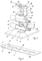
Figur 1- ein Anschlußelement gemäß der Erfindung in perspektivischer Ansicht der Anschlußseite mit vier Schirmkabelanschlüssen,
Figur 2- das Schienenstück des Anschlußelementes nach
Figur 1 in fertiggestanztem, noch nicht gebogenen Zustand, Figur 3- das Anschlußelement nach
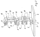
Figur 1 in perspektivischer Ansicht der Betätigungsseite, Figur 4- eine perspektivische Darstellung eines Anschlußelementes mit sechs Schirmkabelanschlüssen,
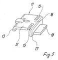
Figur 5- eine Einzelansicht des Druckstückes eines derartigen Anschlußelementes.
- Figure 1
- 1 a connection element according to the invention in a perspective view of the connection side with four shield cable connections,
- Figure 2
- 1 in the finished stamped, not yet bent state,
- Figure 3
- 1 in a perspective view of the actuation side,
- Figure 4
- a perspective view of a connection element with six shield cable connections,
- Figure 5
- a single view of the pressure piece of such a connecting element.
Das Anschlußelement weist ein Schienenstück 1 auf, das zweckmäßig aus
Gründen der vereinfachten Herstellung und der Stabilität einstückig ausgebildet
ist. Wie insbesondere aus den Figuren 1 und 2 für ein Anschlußelement mit insgegsamt
vier Schirmkabelanschlüssen ersichtlich ist, ist im Bodenbereich des
Schienenstückes 1 in dessen Zuschnitt 1' ein um 90° abzubiegendes Befestigungsstück
2 freigestanzt, das mittels einer Schraube 3 an einer Platte 4 oder
dergleichen festgesetzt werden kann, wobei diese Platte 4 dann zumindest in
diesem Anschlußbereich elektrisch leitende Verbindung zu einem PE-Anschluß
hat. The connecting element has a
Im Zusammenhang mit der Freistanzung des Befestigungsstückes 2 sind am Zuschnitt
1' zunächst untere Halteelemente 5 durch entsprechende Freistanzung
gebildet, die ebenfalls um 90° abgebogen werden können und damit als Teil des
zuunterst liegenden Schirmkabelanschlusses eine untere Auflage für das freigelegte
Schirmnetz 6 eines Schirmkabels 7 bilden.In connection with the punching of the
Im Ausführungsbeispiel nach den Figuren 1 und 2 ist der mittlere Bereich des
Zuschnittes 1' im wesentlichen rechtwinklig U-förmig eingebogen, so daß sich
ein nach unten, den Halteelementen 5 gegenüberliegendes Halteelement 8 und
ein weiteres nach oben weisendes Halteelement 8 ergeben. Das obere Ende des
Schienenstückes 1 weist ein weiteres, im wesentlichen rechtwinklig aus dem
Zuschnitt 1' umgebogenes Halteelement 9 auf, das dem nach oben weisenden
Halteelement 8 gegenüberliegt. Die U-förmige Einbiegung mit Bildung der beiden
Halteelemente 8 hat aufgrund der Materialeigenschaften des metallischen Schienenstückes
1 eine gewisse Federwirkung.In the exemplary embodiment according to FIGS. 1 and 2, the middle region of the
Blank 1 'bent substantially at right angles in a U-shape, so that
a downward, the
Im mittleren, U-förmig umzubiegenden Bereich des Zuschnittes 1' des Schienenstückes
1 ist aus Stabilitätsgründen zweckmäßig ein Abstützsteg 10 freigestanzt
und, wie aus Figur 3 ersichtlich, dann nach unten weisend abgebogen.In the middle, U-shaped area of the blank 1 'of the
Mit jedem der Halteelemente 5, 8, 9 der bei diesem Ausführungsbeispiel insgesamt
vier Schirmanschlüsse wirkt jeweils ein Druckstück 11 zusammen, das aus
Figur 5 ersichtlich ist. Die Druckstücke 11 besitzen eine zentrale Druckplatte 12,
deren dem jeweiligen Halteelement 5, 8, 9 zugewandte Seitenfläche dazu dient,
das Schirmkabel 7 mit dem Schirmnetz 6 an das entsprechende Halteelement
anzudrücken. Im freien Außenbereich der Druckplatte 12 sind durch kleine Freistanzungen
und entsprechende Umbiegung jeweils von dem zugeordneten Halteelement
fortweisende kleine Stege 13 gebildet. Da, wie aus den Figuren ersichtlich,
einander gegenüberliegenden Halteelementen 5, 8 bzw. 8, 9 jeweils
paarweise ein Druckstück 11 zugeordnet ist, kann in einfacher Weise jeweils
zwischen einem Paar von Druckstücken 11 eine Feder 14 angeordnet werden,
die die Druckstücke 11 im Sinne der Schließung der beiden betroffenen Schirmkabelanschlüsse
in Richtung auf die Halteelemente und gegebenenfalls die darin
angeordneten Schirmkabel beaufschlagt. Die Stege 13 der Druckstücke 11 ergeben
dabei eine lagegerechte Halterungsmöglichkeit für die Druckfeder 14.With each of the
Die Druckstücke 11 sind ferner an ihren den Stegen 13 abgewandten Enden mit
von außen nach innen verlaufenden beidseitigen Führungsschlitzen 15 versehen,
die zwischen sich einen Steg 16 bilden, an dem sich eine nach unten abgewinkelte
Führungslasche 17 anschließt, von der wieder ein Betätigungselement 18
abgewinkelt ist.The
In dem Schienenstück 1 befinden sich im Bereich zwischen zwei Schirmanschlüssen,
d. h. im Bereich zwischen den Halteelementen 5, 8; 8, 9, rechteckige
Aussparungen 19, die so dimensioniert sind, insbesondere so breit und so hoch
sind, daß nacheinander zunächst ein erstes und dann ein zweites Druckstück
11, hochkant stehend, hindurchgefädelt werden kann, wobei bei dem Hindurchfädeln
dann, wenn die Führungsschlitze 15 dem Randbereich der rechteckigen
Aussparung 19 gegenüberliegt, das Druckstück 11 aus der Hochkantlage in die
Gebrauchslage um 90° verdreht werden kann. Dadurch gelangen die Druckstücke
11 in ihrer aus den Figuren ersichtliche Gebrauchslage, in der sie mit den
Führungsschlitzen 15 und der Führungslasche 17 an dem Schienenstück 1 im
Randbereich der rechteckigen Aussparungen 19 verschieblich geführt sind.In the
Die auf der Betätigungsseite des Anschlußelementes aus dem Schienenstück 1
vorstehenden Betätigungselemente der Druckstücke 11 können einzeln oder
auch paarweise gemeinsam im Sinne der Öffnung des Schirmkabelanschlusses
für die Einsteckung des Schirmkabels gegen die Kraft der Druckfeder 14 betätigt
werden. Nach Freigabe der Betätigungselemente 18 bewirken die Druckfedern
14 die Schließung der Schirmkabelanschlüsse.On the actuating side of the connecting element from the
Abweichend vom dargestellten Ausführungsbeispiel können die Druckstücke auch mit anderweitigen Betätigungselementen verbunden sein, beispielsweise mit emporstehenden kleinen Laschen mit Stecköffnung zum Einstecken eines Betätigungswerkzeuges wie beispielsweise eines Schraubendrehers.Deviating from the illustrated embodiment, the pressure pieces also be connected to other actuators, for example with upstanding little tabs with plug opening for inserting one Operating tool such as a screwdriver.
In Figur 4 ist eine weitere Ausführungsform eines Anschlußelementes dargestellt,
das grundsätzlich den gleichen Aufbau hat wie das vorhergehend beschriebene
Ausführungsbeispiel, wobei hier nur ein Schienenstück 1 vorgesehen
ist, das so lang ist, daß durch U-förmiges Umbiegen im mittleren Bereich insgesamt
vier Halteelemente 8 gebildet sind, drei rechteckige Aussparungen 19 vorhanden
sind und insgesamt sechs Druckstücke 11 montiert sind, so daß bei dieser
Ausführungsform das Anschlußelement insgesamt sechs senkrechte übereinander
angeordnete Schirmkabelanschlüsse aufweist. Unter Beibehaltung des
geschilderten Konstruktionsprinzipes sind auch Anschlußelemente mit 8, 10, 12
oder noch mehr übereinander angeordneten Schirmkabelanschlüssen zu verwirklichen.
Es kann bei großer Anzahl von Schirmkabelanschlüssen an einem derartigen
Anschlußelement zweckmäßig sein, gesonderte Maßnahmen für die Stabiltät
zu treffen, also die Baumaße entsprechend stark auszulegen oder womöglich
mit abstützenden Isolierstoffgehäuseelementen zu arbeiten.FIG. 4 shows a further embodiment of a connection element,
which basically has the same structure as that previously described
Embodiment, only one
Abweichend vom dargestellten und beschriebenen Ausführungsbeispiel ist es auch möglich, den gerade bei größeren Schirmanschlußzahlen aus Stabilitätsgründen zweckmäßigen Schraubbefestigungsanschluß je nach Ausführung durch eine andere Anschlußtechnik, beispielsweise eine Klemm- oder Steckbefestigung auf einer Sammelschiene oder eine sonstige Unterlage zu ersetzen.It is different from the illustrated and described embodiment also possible, especially with larger numbers of shield connections for reasons of stability appropriate screw fastening connection depending on the version another connection technology, for example a clamp or plug-in attachment to replace on a busbar or other base.
Claims (12)
Applications Claiming Priority (2)
| Application Number | Priority Date | Filing Date | Title |
|---|---|---|---|
| DE29715884U | 1997-09-04 | ||
| DE29715884U DE29715884U1 (en) | 1997-09-04 | 1997-09-04 | Connection element for shield cable |
Publications (3)
| Publication Number | Publication Date |
|---|---|
| EP0901186A2 true EP0901186A2 (en) | 1999-03-10 |
| EP0901186A3 EP0901186A3 (en) | 2000-05-17 |
| EP0901186B1 EP0901186B1 (en) | 2005-11-02 |
Family
ID=8045533
Family Applications (1)
| Application Number | Title | Priority Date | Filing Date |
|---|---|---|---|
| EP98115204A Expired - Lifetime EP0901186B1 (en) | 1997-09-04 | 1998-08-13 | Connecting terminal for shielded cables |
Country Status (3)
| Country | Link |
|---|---|
| EP (1) | EP0901186B1 (en) |
| AT (1) | ATE308808T1 (en) |
| DE (2) | DE29715884U1 (en) |
Cited By (1)
| Publication number | Priority date | Publication date | Assignee | Title |
|---|---|---|---|---|
| EP1109256A2 (en) * | 1999-12-16 | 2001-06-20 | Weidmüller Interface GmbH & Co. | Electrical connecting element for the connexion of cable shieldings |
Families Citing this family (5)
| Publication number | Priority date | Publication date | Assignee | Title |
|---|---|---|---|---|
| DE29805077U1 (en) * | 1998-03-20 | 1998-05-20 | Weidmueller Interface | Connection element for electrical conductors, especially shielded conductors |
| DE20014918U1 (en) * | 1999-12-16 | 2001-05-23 | Weidmueller Interface | Connection element for connecting cable shields |
| DE102008016902B3 (en) * | 2008-04-02 | 2009-11-19 | Siemens Aktiengesellschaft | Rail clamp for clamping and electrically contacting rail and e.g. bus bar, has lower clamping space formed between end pieces, where spring whose elastic force of spring causes contact force in upper and lower clamping spaces |
| DE102012105056A1 (en) * | 2012-06-12 | 2013-12-12 | Wago Verwaltungsgesellschaft Mbh | Connection element for electrical conductors |
| DE102016004976A1 (en) | 2015-08-04 | 2017-02-09 | Sew-Eurodrive Gmbh & Co Kg | Holding device and electrical appliance |
Citations (2)
| Publication number | Priority date | Publication date | Assignee | Title |
|---|---|---|---|---|
| DE9410214U1 (en) * | 1994-06-24 | 1994-08-11 | Weidmueller Interface | Connection element for connecting electrical conductors to busbars |
| DE19537585C1 (en) * | 1995-10-09 | 1997-02-13 | Weidmueller Interface | Connection element for connecting the cable shield of a shield cable |
-
1997
- 1997-09-04 DE DE29715884U patent/DE29715884U1/en not_active Expired - Lifetime
-
1998
- 1998-08-13 DE DE59813157T patent/DE59813157D1/en not_active Expired - Lifetime
- 1998-08-13 AT AT98115204T patent/ATE308808T1/en not_active IP Right Cessation
- 1998-08-13 EP EP98115204A patent/EP0901186B1/en not_active Expired - Lifetime
Patent Citations (2)
| Publication number | Priority date | Publication date | Assignee | Title |
|---|---|---|---|---|
| DE9410214U1 (en) * | 1994-06-24 | 1994-08-11 | Weidmueller Interface | Connection element for connecting electrical conductors to busbars |
| DE19537585C1 (en) * | 1995-10-09 | 1997-02-13 | Weidmueller Interface | Connection element for connecting the cable shield of a shield cable |
Cited By (2)
| Publication number | Priority date | Publication date | Assignee | Title |
|---|---|---|---|---|
| EP1109256A2 (en) * | 1999-12-16 | 2001-06-20 | Weidmüller Interface GmbH & Co. | Electrical connecting element for the connexion of cable shieldings |
| EP1109256A3 (en) * | 1999-12-16 | 2004-11-10 | Weidmüller Interface GmbH & Co. | Electrical connecting element for the connexion of cable shieldings |
Also Published As
| Publication number | Publication date |
|---|---|
| ATE308808T1 (en) | 2005-11-15 |
| EP0901186B1 (en) | 2005-11-02 |
| DE29715884U1 (en) | 1997-10-23 |
| DE59813157D1 (en) | 2005-12-08 |
| EP0901186A3 (en) | 2000-05-17 |
Similar Documents
| Publication | Publication Date | Title |
|---|---|---|
| DE102004030085B4 (en) | Terminal for connecting electrical conductors and terminal arrangement | |
| DE2443476C2 (en) | Electrical connector | |
| DE2525641C2 (en) | Apparatus for simultaneously inserting each lead wire from two sets of electrical lead wires into a slot of a single electrical contact of an electrical connector | |
| EP0272200B1 (en) | Connecting block for the telecommunications | |
| EP3284139B1 (en) | Spring clip | |
| CH637506A5 (en) | Electrical terminal connector for connecting at least one insulated wire with at least one two legs having connection element. | |
| EP0959529B1 (en) | Electrical connecting unit | |
| DE19736739A1 (en) | Electrical connection terminal, in particular for use on printed circuit boards | |
| DE2615996A1 (en) | SINGLE-PIECE PUNCHED AND FORMED ELECTRIC CONNECTION CLAMP FROM METAL SHEET | |
| EP3490075A1 (en) | Set consisting of a connector and retaining element and connector and retaining element for same | |
| DE4102784C2 (en) | Connector | |
| DD269496A5 (en) | INSULATION DISPLACEMENT-HUELSENKONTAKT | |
| DE3441416C2 (en) | Electrical connector | |
| DE2449950A1 (en) | SWITCH UNIT | |
| DE102009030645B4 (en) | Brückerelement and set of at least one clamping element and Brückerelement | |
| DE19708649A1 (en) | Electric connector or clamp with transverse bridges | |
| EP0901186B1 (en) | Connecting terminal for shielded cables | |
| EP0122373B1 (en) | Electrical connector | |
| AT409564B (en) | CONNECTION BOX FOR A DATA NETWORK | |
| EP1020954A2 (en) | Electric connecting terminal | |
| DE19914308A1 (en) | Electrical connector for insulated or stripped wire | |
| DE19624511C2 (en) | Contact rail with plug sockets and plug-in module with such a contact rail | |
| EP3855572A1 (en) | Connecting terminal | |
| DE2802643A1 (en) | CONNECTOR | |
| DE102019120305B4 (en) | Conductor connection terminal |
Legal Events
| Date | Code | Title | Description |
|---|---|---|---|
| PUAI | Public reference made under article 153(3) epc to a published international application that has entered the european phase |
Free format text: ORIGINAL CODE: 0009012 |
|
| AK | Designated contracting states |
Kind code of ref document: A2 Designated state(s): AT CH DE ES FR GB IT LI NL SE |
|
| AX | Request for extension of the european patent |
Free format text: AL;LT;LV;MK;RO;SI |
|
| PUAL | Search report despatched |
Free format text: ORIGINAL CODE: 0009013 |
|
| AK | Designated contracting states |
Kind code of ref document: A3 Designated state(s): AT BE CH CY DE DK ES FI FR GB GR IE IT LI LU MC NL PT SE |
|
| AX | Request for extension of the european patent |
Free format text: AL;LT;LV;MK;RO;SI |
|
| RIC1 | Information provided on ipc code assigned before grant |
Free format text: 7H 01R 9/05 A, 7H 01R 4/48 B |
|
| 17P | Request for examination filed |
Effective date: 20000419 |
|
| AKX | Designation fees paid |
Free format text: AT CH DE ES FR GB IT LI NL SE |
|
| GRAP | Despatch of communication of intention to grant a patent |
Free format text: ORIGINAL CODE: EPIDOSNIGR1 |
|
| GRAS | Grant fee paid |
Free format text: ORIGINAL CODE: EPIDOSNIGR3 |
|
| GRAA | (expected) grant |
Free format text: ORIGINAL CODE: 0009210 |
|
| AK | Designated contracting states |
Kind code of ref document: B1 Designated state(s): AT CH DE ES FR GB IT LI NL SE |
|
| PG25 | Lapsed in a contracting state [announced via postgrant information from national office to epo] |
Ref country code: NL Free format text: LAPSE BECAUSE OF FAILURE TO SUBMIT A TRANSLATION OF THE DESCRIPTION OR TO PAY THE FEE WITHIN THE PRESCRIBED TIME-LIMIT Effective date: 20051102 Ref country code: IT Free format text: LAPSE BECAUSE OF FAILURE TO SUBMIT A TRANSLATION OF THE DESCRIPTION OR TO PAY THE FEE WITHIN THE PRESCRIBED TIME-LIMIT;WARNING: LAPSES OF ITALIAN PATENTS WITH EFFECTIVE DATE BEFORE 2007 MAY HAVE OCCURRED AT ANY TIME BEFORE 2007. THE CORRECT EFFECTIVE DATE MAY BE DIFFERENT FROM THE ONE RECORDED. Effective date: 20051102 Ref country code: GB Free format text: LAPSE BECAUSE OF FAILURE TO SUBMIT A TRANSLATION OF THE DESCRIPTION OR TO PAY THE FEE WITHIN THE PRESCRIBED TIME-LIMIT Effective date: 20051102 |
|
| REG | Reference to a national code |
Ref country code: GB Ref legal event code: FG4D Free format text: NOT ENGLISH |
|
| REG | Reference to a national code |
Ref country code: CH Ref legal event code: EP |
|
| REF | Corresponds to: |
Ref document number: 59813157 Country of ref document: DE Date of ref document: 20051208 Kind code of ref document: P |
|
| PG25 | Lapsed in a contracting state [announced via postgrant information from national office to epo] |
Ref country code: SE Free format text: LAPSE BECAUSE OF FAILURE TO SUBMIT A TRANSLATION OF THE DESCRIPTION OR TO PAY THE FEE WITHIN THE PRESCRIBED TIME-LIMIT Effective date: 20060202 |
|
| PG25 | Lapsed in a contracting state [announced via postgrant information from national office to epo] |
Ref country code: ES Free format text: LAPSE BECAUSE OF FAILURE TO SUBMIT A TRANSLATION OF THE DESCRIPTION OR TO PAY THE FEE WITHIN THE PRESCRIBED TIME-LIMIT Effective date: 20060213 |
|
| NLV1 | Nl: lapsed or annulled due to failure to fulfill the requirements of art. 29p and 29m of the patents act | ||
| GBV | Gb: ep patent (uk) treated as always having been void in accordance with gb section 77(7)/1977 [no translation filed] |
Effective date: 20051102 |
|
| PG25 | Lapsed in a contracting state [announced via postgrant information from national office to epo] |
Ref country code: LI Free format text: LAPSE BECAUSE OF NON-PAYMENT OF DUE FEES Effective date: 20060831 Ref country code: CH Free format text: LAPSE BECAUSE OF NON-PAYMENT OF DUE FEES Effective date: 20060831 |
|
| PLBE | No opposition filed within time limit |
Free format text: ORIGINAL CODE: 0009261 |
|
| STAA | Information on the status of an ep patent application or granted ep patent |
Free format text: STATUS: NO OPPOSITION FILED WITHIN TIME LIMIT |
|
| 26N | No opposition filed |
Effective date: 20060803 |
|
| EN | Fr: translation not filed | ||
| PG25 | Lapsed in a contracting state [announced via postgrant information from national office to epo] |
Ref country code: FR Free format text: LAPSE BECAUSE OF FAILURE TO SUBMIT A TRANSLATION OF THE DESCRIPTION OR TO PAY THE FEE WITHIN THE PRESCRIBED TIME-LIMIT Effective date: 20061222 |
|
| REG | Reference to a national code |
Ref country code: CH Ref legal event code: PL |
|
| PG25 | Lapsed in a contracting state [announced via postgrant information from national office to epo] |
Ref country code: AT Free format text: LAPSE BECAUSE OF NON-PAYMENT OF DUE FEES Effective date: 20060813 |
|
| PG25 | Lapsed in a contracting state [announced via postgrant information from national office to epo] |
Ref country code: FR Free format text: LAPSE BECAUSE OF FAILURE TO SUBMIT A TRANSLATION OF THE DESCRIPTION OR TO PAY THE FEE WITHIN THE PRESCRIBED TIME-LIMIT Effective date: 20051102 |
|
| PGFP | Annual fee paid to national office [announced via postgrant information from national office to epo] |
Ref country code: DE Payment date: 20150821 Year of fee payment: 18 |
|
| REG | Reference to a national code |
Ref country code: DE Ref legal event code: R119 Ref document number: 59813157 Country of ref document: DE |
|
| PG25 | Lapsed in a contracting state [announced via postgrant information from national office to epo] |
Ref country code: DE Free format text: LAPSE BECAUSE OF NON-PAYMENT OF DUE FEES Effective date: 20170301 |