EP0258664A2 - Unit for securing electrical lines in distributors of telecommunication installations - Google Patents
Unit for securing electrical lines in distributors of telecommunication installations Download PDFInfo
- Publication number
- EP0258664A2 EP0258664A2 EP87111273A EP87111273A EP0258664A2 EP 0258664 A2 EP0258664 A2 EP 0258664A2 EP 87111273 A EP87111273 A EP 87111273A EP 87111273 A EP87111273 A EP 87111273A EP 0258664 A2 EP0258664 A2 EP 0258664A2
- Authority
- EP
- European Patent Office
- Prior art keywords
- contact
- fuses
- fuse
- assembly
- current
- Prior art date
- Legal status (The legal status is an assumption and is not a legal conclusion. Google has not performed a legal analysis and makes no representation as to the accuracy of the status listed.)
- Withdrawn
Links
Images

Classifications
-
- H—ELECTRICITY
- H01—ELECTRIC ELEMENTS
- H01H—ELECTRIC SWITCHES; RELAYS; SELECTORS; EMERGENCY PROTECTIVE DEVICES
- H01H85/00—Protective devices in which the current flows through a part of fusible material and this current is interrupted by displacement of the fusible material when this current becomes excessive
- H01H85/02—Details
- H01H85/04—Fuses, i.e. expendable parts of the protective device, e.g. cartridges
- H01H85/041—Fuses, i.e. expendable parts of the protective device, e.g. cartridges characterised by the type
- H01H85/046—Fuses formed as printed circuits
-
- H—ELECTRICITY
- H01—ELECTRIC ELEMENTS
- H01T—SPARK GAPS; OVERVOLTAGE ARRESTERS USING SPARK GAPS; SPARKING PLUGS; CORONA DEVICES; GENERATING IONS TO BE INTRODUCED INTO NON-ENCLOSED GASES
- H01T4/00—Overvoltage arresters using spark gaps
- H01T4/06—Mounting arrangements for a plurality of overvoltage arresters
-
- H—ELECTRICITY
- H01—ELECTRIC ELEMENTS
- H01H—ELECTRIC SWITCHES; RELAYS; SELECTORS; EMERGENCY PROTECTIVE DEVICES
- H01H85/00—Protective devices in which the current flows through a part of fusible material and this current is interrupted by displacement of the fusible material when this current becomes excessive
- H01H85/02—Details
- H01H85/20—Bases for supporting the fuse; Separate parts thereof
- H01H2085/2085—Holders for mounting a fuse on a printed circuit
-
- H—ELECTRICITY
- H01—ELECTRIC ELEMENTS
- H01H—ELECTRIC SWITCHES; RELAYS; SELECTORS; EMERGENCY PROTECTIVE DEVICES
- H01H85/00—Protective devices in which the current flows through a part of fusible material and this current is interrupted by displacement of the fusible material when this current becomes excessive
- H01H85/02—Details
- H01H85/04—Fuses, i.e. expendable parts of the protective device, e.g. cartridges
- H01H85/041—Fuses, i.e. expendable parts of the protective device, e.g. cartridges characterised by the type
- H01H85/044—General constructions or structure of low voltage fuses, i.e. below 1000 V, or of fuses where the applicable voltage is not specified
-
- H—ELECTRICITY
- H01—ELECTRIC ELEMENTS
- H01H—ELECTRIC SWITCHES; RELAYS; SELECTORS; EMERGENCY PROTECTIVE DEVICES
- H01H85/00—Protective devices in which the current flows through a part of fusible material and this current is interrupted by displacement of the fusible material when this current becomes excessive
- H01H85/02—Details
- H01H85/44—Structural association with a spark-gap arrester
Definitions
- the invention relates to an assembly for securing electrical lines in distributors of telecommunications, in particular telephone systems.
- Such a flat assembly is known from DE-PS 3212013.
- the assembly is then fitted with power fuses strung together as a series link and can be connected to plug contacts of a layer module in a distributor of a telephone system.
- External lines leading to the subscribers and internal lines leading to the switching devices are connected to insulation displacement connectors of the layer modules connected to the plug contacts.
- the tubular fuses extend across the row direction of the fuses. These are held at their ends with their poles between bent legs of contact parts, which extend from the poles on both sides of a support part of the assembly to the plug contacts.
- the spring legs are bent out of the contact parts around a bending edge lying in the longitudinal direction of the fuse.
- the contact parts in the flat state in the region of the spring legs have a width which is greater than the spacing between the fuses.
- the pitch of the contact parts is considerably larger than that of the assembly.
- the sheet metal consumption is correspondingly large and the finished bent contact parts must be z. B. be connected by injection molding.
- the invention has for its object to enable a material and time-saving attachment of the contact parts.
- the handling of the contact parts is now no wider than in the clamping area.
- the pitch between the fuses is based on the thickness of the fuses at the poles, the width of the spring legs, and the minimum distance between the contact parts. Since the fuses on the poles are relatively thin, the pitch can be reduced so that the overall width of the layer module with the assembly is smaller.
- the contact parts each extend with the same sections in one plane, so that they can be used together in a strip held by connecting webs in the carrier part. Then the connecting webs z. B. cut by punching and the contact parts galvanically isolated.
- the power fuses can e.g. B. be formed as a flat circuit board or as a tubular elements, the poles of z. B. are flattened by squeezing.
- the contact parts are flat in the area of the fuses. Their shape results from a simple stamping contour that is created in one step. Such contact parts are much more dimensionally stable than curved parts, which also require a higher manufacturing effort.
- the training according to claim 2 results in extremely simple contact parts.
- the carrier part is designed as a simple, inexpensive to produce, double-sided laminated circuit board.
- the contact parts can be used in plated-through pads on the circuit board and with this z. B. connected by wave soldering.
- the contact parts are simultaneously formed as connecting parts to the plug contacts of the layer module.
- the base of the fork-shaped contact part can be laid in the flat area, so that the fuse is closer to the carrier part can be set. This makes it possible to reduce the height of the finished assembly.
- the development according to claim 5 makes it possible to sort the individual fuses according to their resistance and to insert two identical fuses into the housing.
- both conductor tracks can be finely etched in one operation under the same conditions, so that the line symmetry is not impaired.
- the fuse wires according to claim 8 can be obtained from two immediately successive sections of a long wire. These two sections are largely of the same nature, which is beneficial to the line affects symmetry.
- the safety wire is also suitable for flattening steep shock waves due to its inductance.
- the development according to claim 9 makes it possible to arrange two separate connections at each end of the base part.
- the development according to claim 11 is based on an assembly according to DE-PS 25 08 845.
- the assembly is then provided with a carrier part produced by injection molding with embedded contact pieces which are provided along a longitudinal edge of the carrier part with contact surfaces for plug contacts of the layer modules.
- the contact pieces are provided with contact zones lying in the plane of the support part for fusible pieces resting on the surge arresters. With their central axis, the surge arresters are perpendicular to the support part.
- a grounding multiple which is U-shaped in cross-section and is made of sheet metal and which rests with spring fingers on the poles of the surge arresters facing away from the carrier part.
- the contact pieces have a U-shaped section which projects into the vicinity of the free ends of the spring fingers. This section lies between the surge arresters and the contact areas. The distance between the bent sections and the spring fingers is less than the thickness of the melting pieces. In the event of a prolonged overload, these melt, so that the contact piece is short-circuited to earth.
- Such a U-shaped bend requires a space corresponding to the distance between the legs.
- a sufficient contact length for the bending tools must be on both sides of the legs be provided.
- the height of the bend can only be formed with a low degree of accuracy, since with such a multiple bend a considerable springback must be expected, which fluctuates depending on the material thickness and the material properties. This changes the distance to the spring fingers of the grounding multiple, so that the exact coordination is not guaranteed with complete certainty.
- the further development according to claim 11 improves the manufacturability and functional reliability of the assembly.
- the section bent up as a simple tab has only one bend which can be produced with a simple tool.
- the contact surface with the spring fingers is the punched-out end face of the contact tab. In the flat state, the position of this end face can be determined with high precision.
- the strip-shaped contact tab can be largely embedded in the carrier part by injection molding, so that its position is reliably stabilized.
- the contact tab can be bent up very close to the surge arrester, which saves considerable space.
- the length and width of the unbent contact piece can be kept small.
- the contact tab can be arranged on the side of the surge arrester facing away from the rear. The earthing multiple points with its earthing fingers in this direction, so that it can be designed as a U-shaped sheet metal part that clasps the back of the assembly.
- the development according to claim 13 results in a space-saving shape of the contact pieces. This makes it possible to provide the module with additional power fuses.
- DE-PS 32 12 013 the bending axes for the contact parts parallel to the longitudinal direction of the contact pieces, so that they have a greater width when unbent.
- the contact part for the power fuse and the contact tab can be closely adjacent, which results in a particularly space-saving arrangement.
- an assembly 1 consists of a double-sided printed circuit board 2 with contact parts 3 and power fuses 4th
- the printed circuit board 2 has along a longitudinal edge perpendicular to this contact surface 5, which are contacted with plug contacts 6 of a layer module of a distributor in a telephone exchange.
- the plug contacts 6 are each formed on an external contact spring 7 and an internal contact spring 8 of a layer component of a distributor in a telephone exchange.
- the external contact springs 7 are connected to the subscriber lines leading outwards and the internal contact springs 8 are connected to the lines leading inwards to the switching system.
- the external and internal contact springs 7 and 8 are connected in pairs to one another via the contact surface 5, conductor tracks 9, the contact parts 3 and the current fuses 4.
- the current fuses 4 are designed as elongated, flat fuse plates which are perpendicular to the printed circuit board 2 over their longitudinal edge. They extend just like the conductor tracks 9 perpendicular to the longitudinal edge of the assembly 1 and are lined up parallel to one another.
- the current fuses 4 are designed as printed circuit boards, at the ends of which the poles 10 are designed as flat contact zones which are connected to one another via a finely etched thin fuse track 11.
- the contact parts 3 are inserted with a soldering mandrel 12 into pressure-contacted solder pads connected to the conductor tracks 9 and are soldered therein. They are designed as flat plates, from which a central longitudinal slot open to their free end is punched out. Spring legs 13 are thus formed on both sides of this longitudinal slot and clamp the current fuses 4 in a resilient manner. They are contacted with the poles of the power fuses 4.
- FIG. 4 other contact parts 14 are formed in their contact area to the power fuses 4 similar to the contact parts 3 according to FIG. 2.
- the printed circuit board 2 is replaced by a carrier part 15 which is produced by injection molding and into which the contact parts 14 are embedded.
- These form the contact surfaces 5 for the plug contacts 6 of the external and internal contact springs 7 and 8 at one end and have the spring legs 13 at their other end. From the contact surfaces 5, the contact parts 14 are guided flat on the carrier part 15 to below the poles 10 of the current fuses 4 and are bent there at right angles to them.
- the spring legs 13 are attached directly above the carrier part 15, so that the current fuse 4 is at a short distance from the carrier part 15.
- a simple current fuse 21 consists of a plate-shaped base part 22, contact surfaces 23 at both ends of the base part 22 and a thin etched conductor track 24 which connects the two contact surfaces 23 to one another.
- two current fuses 21 with the same electrical properties are inserted in the arrow direction in receiving openings 25 of a housing 26 and held clamped therein.
- the housing 26 is shorter than the power fuses 21, so that the contact surfaces 23 can protrude on both sides when inserted.
- the two current fuses 21 held in the housing 26 can be inserted with their two ends between fork-like spring contacts 17 of an electrical assembly 28.
- the spring contacts 27 are connected to electrical conductor tracks of the assembly 28.
- the conductor tracks lead to plug contact points, not shown, which can be connected to contact springs of the distributor connected to the wires of the subscriber lines.
- the two power fuses are to a double power fuse 29 on a common base part summarized.
- the double current fuse 29 has a total of four contact surfaces 23 at both ends on both sides. Two of the contact surfaces 23 at one end are connected to one another via a plated-through solder pad 31 and a thin etched, loop-shaped conductor track 24. The two conductor tracks 24 are arranged next to one another on the same side of the base part 30.
- the current fuse 29 can be inserted with its contact surfaces 23 between galvanically isolated legs 32 from other spring contacts 33. When the power fuse 29 is removed, the legs 32 lie directly against one another with their contact points, so that the electrical connection is maintained even when the power fuse is pulled out.
- another double current fuse 34 is provided with fuse wires 35 instead of the conductor tracks 24 (FIG. 3). These are laid from a contact surface 23 in a loop on one side of the base part 30 and guided through a bore 36 to the other contact surface 23 located at the same end.
- the securing wires 35 are soldered to solder eyes 37 at both ends, which are connected to the contact surfaces 23.
- the fuse wires 35 are laid in a straight line between the two ends on one side of the base part 30.
- the pads 37 are arranged on the same side for both safety wires 15.
- one of the pairs of solder eyes 37 is plated through to the other side and is connected there to the opposite contact surfaces 23. Since the two contact surfaces 23 are each assigned to different cable runs at one end, the associated spring contacts 33 are also open in the unassembled state.
- FIG. 10 another simple current fuse 38 similar to FIG. 5 is provided with a fuse wire 35 instead of the etched conductor track.
- This current fuse can also be inserted into a housing 26 (FIG. 5).
- the housing protects the actual fuse and prevents the fuse from burning tion path that the arc can escape or remains for a long time because the plastic evaporates and extinguishes.
- an assembly 41 consists of a carrier part 42 made of injection molding, contact pieces 43, current fuses 44, surge arresters 45, fusible links 46 and an earthing multiple 47.
- the contact pieces 43 are provided along a longitudinal edge of the carrier part 42 with contact surfaces 48 for plug contacts 49 of contact springs 50 of a layer module, which is arranged in a layer distributor of a telephone switching system.
- the contact pieces 43 are embedded in the carrier part by injection molding and extend essentially perpendicular to the row direction in the plane of the carrier part 42.
- a short contact piece 43 is fork-shaped with its vertically bent free end and engages around a pole of the current fuse 44. The longer one above the other lying contact pieces 43 extend from the contact surfaces 48 to the rear of the carrier part 42, where it forms a contact zone for the melting piece 46.
- the surge arrester 45 is placed, which rests with its other pole on a spring finger 51 of the U-shaped earthing multiple 47 bent from sheet metal.
- a free-punched contact tab 52 is bent out of the longer contact part 43 and projects with its free end into the vicinity of the spring finger 51 and is largely enveloped by the carrier part 42.
- the bending edge lies in the longitudinal direction of the assembly 41.
- the contact tab 52 points in the direction of the contact surface 48 before bending up.
- the long contact piece 43 is in the immediate vicinity of the contact tab 52, another tab in the form of a contact part 53 for the other pole of the power fuse 44 bent out in a similar manner to the contact tab 52.
- the current fuse 44 thus establishes the electrical connection between the two contact pieces 43 and thus between the two contact springs 50.
- the contact part 53 for the power fuse 44 is designed as a flat fork, the material plane of which extends in the longitudinal direction of the assembly.
- the plate-like current fuse 44 is clamped between two side legs of the contact part 53 and contacted.
Abstract
Description
Die Erfindung bezieht sich auf eine Baugruppe zum Sichern von elektrischen Leitungen in Verteilern von Telekommunikations-, insbesondere Fernsprechanlagen.The invention relates to an assembly for securing electrical lines in distributors of telecommunications, in particular telephone systems.
Eine derartige flache Baugruppe ist durch die DE-PS 3212013 bekannt geworden. Danach ist die Baugruppe mit aneinander gereihten Stromsicherungen als Längsglied bestückt und an Steckkontakte eines Schichtbausteines in einem Verteiler einer Fernsprechanlage anschaltbar. Zu den Teilnehmern führende Außenleitungen und zu den Vermittlungseinrichtungen führende Innenleitungen sind an mit den Steckkontakten verbundene Schneidklemmen der Schichtbausteine angeschlossen. Die röhrchenförmigen Sicherungen erstrecken sich quer zur Reihenrichtung der Sicherungen. Diese sind an ihren Enden mit ihren Polen zwischen hochgebogenen Schenkeln von Kontaktteilen gehalten, die sich von den Polen aus zu beiden Seiten eines Trägerteils der Baugruppe zu den Steckkontakten erstrecken. Die Federschenkel sind aus den Kontaktteilen um eine in Längsrichtung der Sicherung liegende Biegekante herausgebogen. Es ist aus der Zeichnung erkennbar, daß die Kontaktteile im flachen Zustand im Bereich der Federschenkel eine Breite aufweisen, die größer ist als der Teilungsabstand zwischen den Sicherungen. In einem Stanzstreifen ist somit der Teilungsabstand der Kontaktteile erheblich größer, als der der Baugruppe. Der Blechverbrauch ist entsprechend groß und die fertig gebogenen Kontaktteile müssen als Einzelteile mit dem Trägerteil z. B. durch Umspritzen verbunden werden.Such a flat assembly is known from DE-PS 3212013. The assembly is then fitted with power fuses strung together as a series link and can be connected to plug contacts of a layer module in a distributor of a telephone system. External lines leading to the subscribers and internal lines leading to the switching devices are connected to insulation displacement connectors of the layer modules connected to the plug contacts. The tubular fuses extend across the row direction of the fuses. These are held at their ends with their poles between bent legs of contact parts, which extend from the poles on both sides of a support part of the assembly to the plug contacts. The spring legs are bent out of the contact parts around a bending edge lying in the longitudinal direction of the fuse. It can be seen from the drawing that the contact parts in the flat state in the region of the spring legs have a width which is greater than the spacing between the fuses. In a stamped strip, the pitch of the contact parts is considerably larger than that of the assembly. The sheet metal consumption is correspondingly large and the finished bent contact parts must be z. B. be connected by injection molding.
Der Erfindung liegt die Aufgabe zugrunde, eine material- und zeitsparende Anbringung der Kontaktteile zu ermöglichen.The invention has for its object to enable a material and time-saving attachment of the contact parts.
Diese Aufgabe wird durch die Erfindung gemäß Anspruch 1 gelöst. Die Kontaktteile werden nun in ihrer Abwicklung nicht breiter als im Klemmbereich. Die Teilungsbreite zwischen den Sicherungen bemißt sich nach der Dicke der Sicherungen an den Polen, der Breite der Federschenkel, sowie dem Mindestabstand zwischen den Kontaktteilen. Da die Sicherungen an den Polen relativ dünn sind, kann der Teilungsabstand verringert werden, so daß sich eine geringere Gesamtbreite des Schichtbausteins mit der Baugruppe ergibt. Die Kontaktteile erstrecken sich mit gleichen Abschnitten jeweils in einer Ebene, so daß sie gemeinsam an einem Streifen über Verbindungsstege zusammengehalten in das Trägerteil eingesetzt werden können. Danach werden die Verbindungsstege z. B. durch Stanzen abgeschnitten und die Kontaktteile galvanisch getrennt. Die Stromsicherungen können z. B. als flache Leiterplättchen oder als röhrchenförmige Elemente ausgebildet sein, deren Pole z. B. durch Quetschen abgeflacht sind.This object is achieved by the invention according to
Die Kontaktteile sind im Bereich der Sicherungen flach ausgebil-det. Ihre Form ergibt sich aus einer einfachen Stanzkontur, die in einem Schritt erzeugt wird. Derartige Kontaktteile sind wesentlich maßhaltiger als gebogene Teile, die zudem einen höheren Fertigungsaufwand erfordern.The contact parts are flat in the area of the fuses. Their shape results from a simple stamping contour that is created in one step. Such contact parts are much more dimensionally stable than curved parts, which also require a higher manufacturing effort.
Vorteilhafte Weiterbildungen der Erfindung sind in den Ansprüchen 2 bis 10 gekennzeichnet:Advantageous developments of the invention are characterized in
Durch die Weiterbildung nach Ansrpuch 2 ergeben sich äußerst einfache Kontaktteile. Das Trägerteil ist als einfache, kostengünstig herzustellende, doppelseitig kaschierte Leiterplatte ausgebildet. Die Kontaktteile können in durchkontaktierte Lötaugen der Leiterplatte eingesetzt und mit dieser z. B. durch Schwallöten verbunden werden.The training according to
Durch die Weiterbildung nach Anspruch 3 sind die Kontaktteile gleichzeitig auch als Verbindungsteile zu den Steckkontakten des Schichtbausteins ausgebildet. Die Basis des gabelförmigen Kontaktteiles kann in den flach liegenden Bereich verlegt werden, so daß die Sicherung mit geringerem Abstand zum Trägerteil ein gesetzt werden kann. Dadurch ist es möglich, die Bauhöhe der fertigen Baugruppe zu verringern.Through the development according to
Die Weiterbildung nach Anspruch 4 geht davon aus, daß für jede Ader einer Teilnehmerleitung eine Stromsicherung vorgesehen ist. Diese ist an beiden Enden mit Kontaktflächen versehen, die in gabelartigen Federkontakten der Baugruppe gehalten sind. Bei derartig einzeln eingesetzten Sicherungen kann es infolge von Abweichungen der elektrischen Eigenschaften zu Störungen der Leitungssymmetrie einer Doppelader kommen.The development according to
Durch die Zusammenfassung zweier Sicherungen in einem Bauteil ist es möglich, die Widerstandswerte beider Sicherungen in hohem Maße einander anzugleichen. Beim Durchschmelzen einer Sicherung ist gewährleistet, daß auch die andere Sicherung ausgewechselt wird und daß ein neues bereits werkseitig aufeinander abgestimmtes Sicherungspaar eingesetzt werden kann.By combining two fuses in one component, it is possible to match the resistance values of both fuses to a high degree. When a fuse blows, it is ensured that the other fuse is also replaced and that a new pair of fuses which are already matched to one another at the factory can be used.
Die Weiterbildung nach Anspruch 5 ermöglicht es, die einzelnen Sicherungen nach ihrem Widerstand zu sortieren und jeweils zwei gleiche Sicherungen in das Gehäuse einzusetzen.The development according to
Die Weiterbildung nach Anspruch 6 ermöglicht die Herstellung beider Sicherungen in einem Zuge unter gleichen Bedingungen. Auf diese Weise kann auch hier bei den Widerstandswerten ein hohes Maß an Übereinstimmung erzeugt werden. Außerdem ergeben sich bei der Herstellung und Montage Kostenvorteile.The development according to
Durch die Weiterbildung nach Anspruch 7 können beide Leiterbahnen in einem Arbeitsgang unter gleichen Bedingungen feingeätzt werden, so daß die Leitungssymmetrie nicht beeinträchtigt wird.Through the development according to claim 7, both conductor tracks can be finely etched in one operation under the same conditions, so that the line symmetry is not impaired.
Die Sicherungsdrähte nach Anspruch 8 können aus zwei unmittelbar aufeinanderfolgenden Abschnitten eines langen Drahtes gewonnen werden. Diese beiden Abschnitte sind von weitgehend gleicher Beschaffenheit, was sich günstig auf die Leitungs symmetrie auswirkt. Der Sicherungsdraht ist außerdem geeignet, aufgrund seiner Induktivität steile Stoßwellen abzuflachen.The fuse wires according to
Die Weiterbildung nach Anspruch 9 ermöglicht es, an beiden Enden des Basisteils je zwei getrennte Anschlüsse anzuordnen.The development according to
Durch die Weiterbildung nach Anspruch 10 ist es möglich, auch Baugruppen ohne Stromsicherungen zu verwenden, ohne daß die Leiterzüge unterbrochen werden.Through the development according to
Die Weiterbildung nach Anspruch 11 geht von einer Baugruppe nach der DE-PS 25 08 845 aus. Danach ist die Baugruppe mit einem im Spritzguß hergestellten Trägerteil mit eingelassenen Kontaktstücken versehen, die entlang einer Längskante des Trägerteils mit Kontaktflächen für Steckkontakte der Schichtbausteine versehen sind. Zum anderen Ende hin sind die Kontaktstücke mit in der Ebene des Trägerteiles liegenden Kontaktzonen für an den Überspannungsableitern anliegende Schmelzstücke versehen. Die Überspannungsableiter stehen mit ihrer Mittelachse senkrecht zum Trägerteil. Auf der den Kontaktflächen abgewandten Rückseite der Baugruppe ist ein im Querschnitt U-förmiges, aus Blech gebogenes Erdungsvielfach angeordnet, das mit Federfingern an den vom Trägerteil abgewandten Polen der Überspannungsableiter anliegt.The development according to
Die Kontaktstücke weisen einen U-förmig hochgebogenen Abschnitt auf, der in die Nähe der freien Enden der Federfinger ragt. Dieser Abschnitt liegt zwischen den Überspannungsableitern und den Kontaktflächen. Der Abstand zwischen den hochgebogenen Abschnitten und den Federfingern ist geringer als die Dicke der Schmelzstücke. Bei einer länger andauernden Überlastung schmelzen diese, so daß das Kontaktstück gegen Erde kurzgeschlossen wird.The contact pieces have a U-shaped section which projects into the vicinity of the free ends of the spring fingers. This section lies between the surge arresters and the contact areas. The distance between the bent sections and the spring fingers is less than the thickness of the melting pieces. In the event of a prolonged overload, these melt, so that the contact piece is short-circuited to earth.
Eine derartige U-förmige Biegung benötigt einen dem Schenkelabstand entsprechenden Raum. Zudem muß zu beiden Seiten der Schenkel eine hinreichende Anlagelänge für die Biegewerkzeuge vorgesehen werden. Die Höhe der Biegung kann nur mit einer geringen Genauigkeit ausgebildet werden, da bei einer derartigen Vielfachbiegung mit einer beträchtlichen Rückfederung gerechnet werden muß, die in Abhängigkeit von der Materialdicke und den Materialeigenschaften schwankt. Dadurch verändert sich der Abstand zu den Federfingern des Erdungsvielfaches, so daß die genaue Abstimmung nicht mit völliger Sicherheit gewährleistet ist.Such a U-shaped bend requires a space corresponding to the distance between the legs. In addition, a sufficient contact length for the bending tools must be on both sides of the legs be provided. The height of the bend can only be formed with a low degree of accuracy, since with such a multiple bend a considerable springback must be expected, which fluctuates depending on the material thickness and the material properties. This changes the distance to the spring fingers of the grounding multiple, so that the exact coordination is not guaranteed with complete certainty.
Durch die Weiterbildung nach Anspruch 11 wird die Herstellbarkeit und Funktionssicherheit der Baugruppe verbessert. Der als einfacher Lappen hochgebogene Abschnitt weist nur noch eine Biegung auf, die mit einem einfachen Werkzeug hergestellt werden kann. Die Anlagefläche zu den Federfingern ist die freigestanzte Stirnseite des Kontaktlappens. Im flachen Zustand kann die Lage dieser Stirnseite hochgenau festgelegt werden. Beim anschließenden Biegen um die einzige Biegekante kann auch der Abstand der Stirnseite des Kontaktlappens zur Basis des Kontaktstückes sehr genau eingehalten werden. Der streifenförmige Kontaktlappen kann weitgehend durch Umspritzen in das Trägerteil einebettet werden, so daß seine Lage zuverlässig stabilisiert wird. Der Kontaktlappen kann sehr knapp neben dem Überspannungsableiter hochgebogen werden, was eine erhebliche Raumersparnis darstellt.The further development according to
Durch die Weiterbildung nach Anspruch 12 können Länge und Breite des ungebogenen Kontaktstückes klein gehalten werden. Der Kontaktlappen kann auf der der Rückseite abgewandten Seite der Überspannungsableiter angeordnet sein. Das Erdungsvielfach weist mit seinen Erdungsfingern in diese Richtung, so daß es als U-förmiges Blechteil ausgebildet werden kann, das die Rückseite der Baugruppe umklammert.Through the development according to
Durch die Weiterbildung nach Anspruch 13 ergibt sich eine raum-sparende Form der Kontaktstücke. Dadurch ist es möglich, die Baugruppe zusätzlich mit den Stromsicherungen zu versehen. Nach der DE-PS 32 12 013 liegen die Biegeachsen für die Kontaktteile parallel zur Längsrichtung der Kontaktstücke, so daß diese im ungebogenen Zustand eine höhere Breite aufweisen. Nach der Erfindung können das Kontaktteil für die Stromsicherung und der Kontaktlappen einander eng benachbart sein, was eine besonders raumsparende Anordnung ergibt.The development according to claim 13 results in a space-saving shape of the contact pieces. This makes it possible to provide the module with additional power fuses. According to DE-PS 32 12 013, the bending axes for the contact parts parallel to the longitudinal direction of the contact pieces, so that they have a greater width when unbent. According to the invention, the contact part for the power fuse and the contact tab can be closely adjacent, which results in a particularly space-saving arrangement.
Im folgenden wird die Erfindung anhand von in der Zeichnung dargestellten Ausführungsbeispielen näher erläutert.The invention is explained in more detail below on the basis of exemplary embodiments illustrated in the drawing.
Es zeigen:
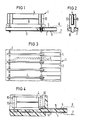
- Fig. 1 einen Schnitt durch einen Teil einer elektrischen Baugruppe mit Stromsicherungen,
- Fig. 2 eine Seitenansicht eines Teils der Baugruppe nach Fig 1,
- Fig. 3 eine Draufsicht auf die Baugruppe nach Fig 1,
- Fig. 4 einen Schnitt durch eine andere Baugruppe mit einer Stromsicherung,
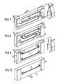
- Fig. 5 perspektivisch ein Gehäuse zur Aufnahme zweier Stromsicherungen,
- Fig. 6 perspektivisch das Gehäuse nach Fig. 5 mit den Stromsicherungen unmittelbar vor dem Einsetzen in Federkontakte einer elektrischen Baugruppe,
- Fig. 7 eine zweifache Stromsicherung mit geätzten Leiterbahnen sowie ein Paar anderer Federkontakte der elektrischen Baugruppe,
- Fig. 8 eine zweifache Stromsicherung ähnlich Fig. 7 mit schleifenförmig verlegten Sicherungsdrähten,
- Fig. 9 eine zweifache Stromsicherung ähnlich Fig. 8 mit geradlinig verlegten Sicherungsdrähten und einem Paar geöffneter Federkontakte,
- Fig. 10 eine einfache Stromsicherung ähnlich Fig. 9,
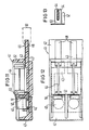
- Fig. 11 einen seitlichen Schnitt durch eine Baugruppe mit Stromsicherungen und Überspannungsableitern,
- Fig. 12 eine Draufsicht auf die Baugruppe nach Fig. 11
- Fig. 13 eine Seitenansicht eines Kontaktteils der Baugruppe nach Fig. 12.
- 1 shows a section through part of an electrical assembly with current fuses,
- 2 is a side view of part of the assembly of FIG. 1,
- 3 is a top view of the assembly of FIG. 1;
- 4 shows a section through another assembly with a current fuse,
- 5 is a perspective view of a housing for receiving two current fuses,
- 6 in perspective the housing according to FIG. 5 with the current fuses immediately before being inserted into spring contacts of an electrical assembly,
- 7 shows a double current fuse with etched conductor tracks and a pair of other spring contacts of the electrical assembly,
- 8 shows a double current fuse similar to FIG. 7 with looped fuse wires,
- 9 shows a double current fuse similar to FIG. 8 with straight fuse wires and a pair of open spring contacts,
- 10 is a simple power fuse similar to FIG. 9,
- 11 shows a side section through an assembly with current fuses and surge arresters,
- 12 is a plan view of the assembly of FIG. 11th
- 13 is a side view of a contact part of the assembly of FIG. 12.
Nach Fig. 1 und 2 besteht eine Baugruppe 1 aus einer doppelseitig gedruckten Leiterplatte 2 mit Kontaktteilen 3 und Stromsicherungen 4.1 and 2, an
Die Leiterplatte 2 weist entlang einer Längskante sich senkrecht zu dieser erstreckende Kontaktfläche 5 auf, die mit Steckkontakten 6 eines Schichtbausteines eines Verteilers in einer Fernsprechvermittlungsanlage kontaktiert sind. Die Steckkontakte 6 sind jeweils an einer Außenkontaktfeder 7 und einer Innenkontaktfeder 8 eines Schichtbausteines eines Verteilers in einer Fernsprechvermittlungsanlage ausgebildet. Die Außenkontaktfedern 7 sind mit den nach außen führenden Teilnehmerleitungen und die Innenkontaktfedern 8 mit den nach innen zur Vermittlungsanlage führenden Leitungen verbunden. Die Außen- und Innenkontaktfedern 7 und 8 sind paarweise über die Kontaktfläche 5, Leiterbahnen 9, die Kontaktteile 3 und die Stromsicherungen 4 miteinander verbunden.The printed
Die Stromsicherungen 4 sind als längliche, flache Sicherungsplättchen ausgebildet, die über ihrer Längskante senkrecht zur Leiterplatte 2 stehen. Sie erstrecken sich ebenso wie im wesentlichen die Leiterbahnen 9 senkrecht zur Längskante der Baugruppe 1 und sind parallel zu dieser aneinandergereiht.The
Die Stromsicherungen 4 sind als gedruckte Leiterplatten ausgebildet, an deren Enden die Pole 10 als flache Kontaktzonen ausgebildet sind, die über eine fein geätzte dünne Sicherungsbahn 11 miteinander verbunden sind. Die Kontaktteile 3 sind mit einem Lötdorn 12 in mit den Leiterbahnen 9 verbundene durckkontaktierte Lötaugen eingesetzt und darin verlötet. Sie sind als flache Plättchen ausgebildet, aus denen ein zu ihrem freien Ende hin offener mittlerer Längsschlitz ausgestanzt ist. Zu beiden Seiten dieses Längsschlitzes sind dadurch Federschenkel 13 gebildet, die die Stromsicherungen 4 federnd einklemmen. Dabei sind sie mit den Polen der Stromsicherungen 4 kontaktiert.The
Nach Fig. 4 sind andere Kontaktteile 14 in ihrem Kontaktierbereich zu den Stromsicherungen 4 ähnlich den Kontaktteilen 3 nach Fig. 2 ausgebildet. Die gedruckte Leiterplatte 2 ist jedoch durch ein im Spritzguß hergestelltes Trägerteil 15 ersetzt, in das die Kontaktteile 14 eingelassen sind. Diese bilden an einem Ende die Kontaktflächen 5 für die Steckkontakte 6 der Außen-und Innenkontaktfedern 7 und 8. An ihrem anderen Ende weisen sie die Federschenkel 13 auf. Von den Kontaktflächen 5 aus sind die Kontaktteile 14 flach an dem Trägerteil 15 bis unter die Pole 10 der Stromsicherungen 4 geführt und dort rechtwinkelig zu diesen gebogen. Die Federschenkel 13 sind unmittelbar über dem Trägerteil 15 angesetzt, so daß die Stromsicherung 4 einen geringen Abstand zum Trägerteil 15 aufweist.According to FIG. 4, other contact parts 14 are formed in their contact area to the power fuses 4 similar to the
Nach Fig. 5 besteht eine einfache Stromsicherung 21 aus einem plattenförmigen Basisteil 22, Kontaktflächen 23 an beiden Enden des Basisteils 22 sowie einer dünnen geätzten Leiterbahn 24, die die beiden Kontaktflächen 23 miteinander verbindet. Jeweils zwei Stromsicherungen 21 gleicher elektrischer Eigenschaften werden in der Pfeilrichtung in Aufnahmeöffnungen 25 eines Gehäuses 26 eingeschoben und klemmend darin gehalten. Das Gehäuse 26 ist kürzer als die Stromsicherungen 21, so daß die Kontaktflächen 23 im eingeschobenen Zustand zu beiden Seiten herausragen können.5, a simple
Nach Fig. 6 können die beiden in dem Gehäuse 26 gehaltenen Stromsicherungen 21 mit ihren beiden Enden zwischen gabelartige Federkontakte 17 einer elektrischen Baugruppe 28 eingeschoben werden. Die Federkontakte 27 sind mit elektrischen Leiterbahnen der Baugruppe 28 verbunden. Die Leiterbahnen führen zu nicht dargestellten Steckkontaktstellen, die an mit den Adern der Teilnehmerleitungen verbundene Kontaktfedern des Verteilers anschaltbar sind.6, the two
Nach Fig. 7 sind die beiden Stromsicherungen zu einer zweifachen Stromsicherung 29 an einem gemeinsamen Basisteil zu sammengefaßt. Die zweifache Stromsicherung 29 weist an beiden Enden zu beiden Seiten insgesamt vier Kontaktflächen 23 auf. Je zwei der Kontaktflächen 23 an einem Ende sind über ein durchkontaktiertes Lötauge 31 und eine dünne geätzte, schleifenförmig verlegte Leiterbahn 24 miteinander verbunden. Die beiden Leiterbahnen 24 sind auf der gleichen Seite des Basisteils 30 nebeneinanderliegend angeordnet. Die Stromsicherung 29 ist mit ihren Kontaktflächen 23 zwischen galvanisch getrennte Schenkel 32 von anderen Federkontakten 33 einschiebbar. Die Schenkel 32 liegen bei entfernter Stromsicherung 29 mit ihren Kontaktstellen unmittelbar aneinander, so daß die elektrische Verbindung auch bei ausgezogener Stromsicherung erhalten bleibt.7, the two power fuses are to a
Nach Fig. 8 ist eine andere zweifache Stromsicherung 34 anstelle der Leiterbahnen 24 (Fig. 3) mit Sicherungsdrähten 35 versehen. Diese sind von einer Kontaktfläche 23 aus schleifenförmig an einer Seite des Basisteils 30 verlegt und durch eine Bohrung 36 zur anderen, am gleichen Ende gelegenen Kontaktfläche 23 geführt. Die Sicherungsdrähte 35 sind an beiden Enden an Lötaugen 37 angelötet, die mit den Kontaktflächen 23 verbunden sind.According to FIG. 8, another double
Nach Fig. 9 sind die Sicherungsdrähte 35 geradlinig zwischen den beiden Enden auf einer Seite des Basisteils 30 verlegt. Die Lötaugen 37 sind für beide Sicherungsdrähte 15 auf der gleichen Seite angeordnet. Jedoch ist eines der Lötaugenpaare 37 zur anderen Seite durchkontaktiert und dort mit den gegenüberliegenden Kontaktflächen 23 verbunden. Da die beiden Kontaktflächen 23 an jeweils einem Ende unterschiedlichen Leitungszügen zugeordnet sind, sind auch die zugehörigen Federkontakte 33 im unbestückten Zustand geöffnet.9, the
Nach Fig. 10 ist eine andere einfache Stromsicherung 38 ähnlich Fig. 5 anstelle der geätzten Leiterbahn mit einem Sicherungsdraht 35 versehen. Diese Stromsicherung kann ebenfalls in ein Gehäuse 26 (Fig. 5) eingesetzt werden. Das Gehäuse schützt die eigentliche Sicherung und verhindert beim Abbrennen der Siche rungsbahn, daß der Lichtbogen nach außen treten kann oder längere Zeit stehen bleibt, da der Kunststoff verdampft und löscht.According to FIG. 10, another simple
Nach den Fig. 11 und 12 besteht eine Baugruppe 41 aus einem aus Spritzguß hergestellten Trägerteil 42, Kontaktstücken 43, Stromsicherungen 44, Überspannungsableitern 45, Schmelzstücken 46 und einem Erdungsvielfach 47.11 and 12, an
Die Kontaktstücke 43 sind entlang einer Längskante des Trägerteiles 42 mit Kontaktflächen 48 für Steckkontakte 49 von Kontaktfedern 50 eines Schichtbausteines versehen, der in einem Schichtverteiler einer Fernsprechvermittlungsanlage angeordnet ist. Die Kontaktstücke 43 sind in dem Trägerteil durch Umspritzen eingelassen und erstrecken sich im wesentlichen senkrecht zur Reihenrichtung in der Ebene des Trägerteiles 42. Ein kurzes Kontaktstück 43 ist mit seinem senkrecht hochgebogenen freien Ende gabelförmig ausgebildet und umgreift einen Pol der Stromsicherung 44. Das längere der übereinander liegenden Kontaktstücke 43 erstreckt sich von den Kontaktflächen 48 aus bis zur Rückseite des Trägerteils 42, wo es eine Kontaktzone für das Schmelzstück 46 bildet. Auf dieses ist der Überspannungsableiter 45 aufgesetzt, der mit seinem anderen Pol an einem Federfinger 51 des U-förmig aus Blech gebogenen Erdungsvielfaches 47 anliegt. Neben dem mit seiner Mittelachse senkrecht zum Trägerteil 42 stehenden Überspannungsableiter 45 ist aus dem längeren Kontaktteil 43 ein freigestanzter Kontaktlappen 52 hochgebogen, der mit seinem freien Ende bis in die Nähe des Federfingers 51 ragt und weitgehend vom Trägerteil 42 umhüllt ist. Die Biegekante liegt in der Längsrichtung der Baugruppe 41. Der Kontaktlappen 52 weist vor dem Hochbiegen in die Richtung der Kontaktfläche 48. Aus dem langen Kontaktstück 43 ist in unmittelbarer Nachbarschaft des Kontaktlappens 52 ein weiterer Lappen in Form eines Kontaktteiles 53 für den anderen Pol der Stromsicherung 44 in ähnlicher Weise wie der Kontaktlappen 52 herausgebogen. Damit stellt die Stromsicherung 44 die elektrische Verbindung zwischen den beiden Kontaktstücken 43 und damit zwischen den beiden Kontaktfedern 50 her.The
Nach Fig. 13 ist das Kontaktteil 53 für die Stromsicherung 44 als flache Gabel ausgebildet, deren Materialebene sich in der Längsrichtung der Baugruppe erstreckt. Die plättchenartige Stromsicherung 44 ist zwischen zwei Seitenschenkeln des Kontaktteiles 53 eingeklemmt und kontaktiert.13, the
Claims (13)
Applications Claiming Priority (6)
| Application Number | Priority Date | Filing Date | Title |
|---|---|---|---|
| DE3628804 | 1986-08-25 | ||
| DE3628841 | 1986-08-25 | ||
| DE3628806 | 1986-08-25 | ||
| DE3628841 | 1986-08-25 | ||
| DE3628804 | 1986-08-25 | ||
| DE3628806 | 1986-08-25 |
Publications (2)
| Publication Number | Publication Date |
|---|---|
| EP0258664A2 true EP0258664A2 (en) | 1988-03-09 |
| EP0258664A3 EP0258664A3 (en) | 1990-03-21 |
Family
ID=27194761
Family Applications (1)
| Application Number | Title | Priority Date | Filing Date |
|---|---|---|---|
| EP87111273A Withdrawn EP0258664A3 (en) | 1986-08-25 | 1987-08-04 | Unit for securing electrical lines in distributors of telecommunication installations |
Country Status (4)
| Country | Link |
|---|---|
| EP (1) | EP0258664A3 (en) |
| AU (1) | AU598849B2 (en) |
| FI (1) | FI873656A (en) |
| NO (1) | NO873577L (en) |
Cited By (4)
| Publication number | Priority date | Publication date | Assignee | Title |
|---|---|---|---|---|
| EP1710825A2 (en) * | 2005-04-04 | 2006-10-11 | Patent-Treuhand-Gesellschaft für elektrische Glühlampen mbH | Fuse assembly for protection of an electric device against overcurrent |
| EP1990818A2 (en) * | 2007-05-10 | 2008-11-12 | Delphi Technologies, Inc. | System and method for interconnecting a plurality of printed circuits |
| WO2018144475A1 (en) * | 2017-01-31 | 2018-08-09 | Continental Automotive Systems, Inc. | In-line blade fuse system |
| CN112956068A (en) * | 2018-11-16 | 2021-06-11 | 日本汽车能源株式会社 | Battery module |
Families Citing this family (3)
| Publication number | Priority date | Publication date | Assignee | Title |
|---|---|---|---|---|
| EP0258629A3 (en) * | 1986-08-25 | 1990-01-31 | Siemens Aktiengesellschaft | Module for protecting electrical lines in telecommunication installations |
| DE3750564D1 (en) * | 1986-08-25 | 1994-10-27 | Siemens Ag | Assembly for securing electrical lines in distributors of telecommunications systems. |
| NZ234141A (en) * | 1989-06-28 | 1992-10-28 | Siemens Ag | Safety connector to distribution frame for voltage surge protectors |
Citations (6)
| Publication number | Priority date | Publication date | Assignee | Title |
|---|---|---|---|---|
| DE1249935B (en) * | 1962-07-24 | 1967-09-14 | ||
| DE2720220A1 (en) * | 1977-05-05 | 1978-11-16 | Siemens Ag | Fuse panel with double row of contact elements - accommodates one or more cassettes each carrying several fuses engaging pairs of contacts |
| GB1534967A (en) * | 1975-02-28 | 1978-12-06 | Siemens Ag | Fuse devices |
| DE3024864A1 (en) * | 1980-07-01 | 1982-01-21 | Licentia Patent-Verwaltungs-Gmbh, 6000 Frankfurt | Surge arrester mounting for LV circuits - has button type arrester clamped by spring pressure between line and earth bar |
| GB2117577A (en) * | 1982-03-31 | 1983-10-12 | Siemens Ag | An electrical distributor segment for telephone exchange systems |
| US4504883A (en) * | 1982-05-20 | 1985-03-12 | Kabushiki Kaisha Sankosha | Arrester holder apparatus for distributor of communication apparatus |
Family Cites Families (3)
| Publication number | Priority date | Publication date | Assignee | Title |
|---|---|---|---|---|
| EP0254126A3 (en) * | 1986-07-24 | 1989-03-29 | Siemens Aktiengesellschaft | Plug-in assemblage with fuses for distributing frame |
| EP0258629A3 (en) * | 1986-08-25 | 1990-01-31 | Siemens Aktiengesellschaft | Module for protecting electrical lines in telecommunication installations |
| DE3750564D1 (en) * | 1986-08-25 | 1994-10-27 | Siemens Ag | Assembly for securing electrical lines in distributors of telecommunications systems. |
-
1987
- 1987-08-04 EP EP87111273A patent/EP0258664A3/en not_active Withdrawn
- 1987-08-24 FI FI873656A patent/FI873656A/en not_active Application Discontinuation
- 1987-08-24 AU AU77353/87A patent/AU598849B2/en not_active Ceased
- 1987-08-25 NO NO873577A patent/NO873577L/en unknown
Patent Citations (6)
| Publication number | Priority date | Publication date | Assignee | Title |
|---|---|---|---|---|
| DE1249935B (en) * | 1962-07-24 | 1967-09-14 | ||
| GB1534967A (en) * | 1975-02-28 | 1978-12-06 | Siemens Ag | Fuse devices |
| DE2720220A1 (en) * | 1977-05-05 | 1978-11-16 | Siemens Ag | Fuse panel with double row of contact elements - accommodates one or more cassettes each carrying several fuses engaging pairs of contacts |
| DE3024864A1 (en) * | 1980-07-01 | 1982-01-21 | Licentia Patent-Verwaltungs-Gmbh, 6000 Frankfurt | Surge arrester mounting for LV circuits - has button type arrester clamped by spring pressure between line and earth bar |
| GB2117577A (en) * | 1982-03-31 | 1983-10-12 | Siemens Ag | An electrical distributor segment for telephone exchange systems |
| US4504883A (en) * | 1982-05-20 | 1985-03-12 | Kabushiki Kaisha Sankosha | Arrester holder apparatus for distributor of communication apparatus |
Cited By (7)
| Publication number | Priority date | Publication date | Assignee | Title |
|---|---|---|---|---|
| EP1710825A2 (en) * | 2005-04-04 | 2006-10-11 | Patent-Treuhand-Gesellschaft für elektrische Glühlampen mbH | Fuse assembly for protection of an electric device against overcurrent |
| EP1710825A3 (en) * | 2005-04-04 | 2007-10-24 | Patent-Treuhand-Gesellschaft für elektrische Glühlampen mbH | Fuse assembly for protection of an electric device against overcurrent |
| EP1990818A2 (en) * | 2007-05-10 | 2008-11-12 | Delphi Technologies, Inc. | System and method for interconnecting a plurality of printed circuits |
| EP1990818A3 (en) * | 2007-05-10 | 2009-12-09 | Delphi Technologies, Inc. | System and method for interconnecting a plurality of printed circuits |
| US7701321B2 (en) | 2007-05-10 | 2010-04-20 | Delphi Technologies, Inc. | System and method for interconnecting a plurality of printed circuits |
| WO2018144475A1 (en) * | 2017-01-31 | 2018-08-09 | Continental Automotive Systems, Inc. | In-line blade fuse system |
| CN112956068A (en) * | 2018-11-16 | 2021-06-11 | 日本汽车能源株式会社 | Battery module |
Also Published As
| Publication number | Publication date |
|---|---|
| NO873577L (en) | 1988-02-26 |
| FI873656A (en) | 1988-02-26 |
| FI873656A0 (en) | 1987-08-24 |
| AU7735387A (en) | 1988-02-25 |
| EP0258664A3 (en) | 1990-03-21 |
| NO873577D0 (en) | 1987-08-25 |
| AU598849B2 (en) | 1990-07-05 |
Similar Documents
| Publication | Publication Date | Title |
|---|---|---|
| DE3137429C2 (en) | Connection device in a connection strip | |
| EP0634888B1 (en) | Plug-in unit, particularly relay module for motor vehicles | |
| DE4017423C2 (en) | ||
| DE3021798A1 (en) | DEVICE AND METHOD FOR PRODUCING A DOUBLE CONTACT ON A LOCK-, SCREW- AND INSULATION-FREE CLAMP CONNECTOR | |
| DE2525641A1 (en) | DEVICE FOR INSERTING EACH WIRE OF TWO ELECTRIC WIRE GROUPS SIMULTANEOUSLY INTO A SLOT OF A SINGLE ELECTRICAL CONTACT OF AN ELECTRICAL CONNECTOR | |
| WO2004093275A1 (en) | Overvoltage protection magazine for a device of telecommunications technology | |
| DE1615666C3 (en) | Electric ferrule | |
| DE2815634C2 (en) | Electrical connector | |
| EP0856911A1 (en) | Multipole terminal block | |
| EP0086316B1 (en) | Plug-in contact device for the establishment of an electrical connection between two bus-bars | |
| EP0258664A2 (en) | Unit for securing electrical lines in distributors of telecommunication installations | |
| DE2603151C3 (en) | Component for switching and / or isolating strips in distributors for telecommunications systems | |
| EP0634813A2 (en) | Distribution block | |
| DE1195385B (en) | Clampable contact piece for telecommunications, especially telephone systems | |
| EP0890205B1 (en) | Distribution device for a distribution board in a telecommunication system | |
| DE3625238C2 (en) | ||
| DE60208260T2 (en) | Improved busbar with insulated terminals and associated connector guide | |
| EP1020954A2 (en) | Electric connecting terminal | |
| EP0990280B1 (en) | Protective connector for a telecommunications device | |
| EP1587166A1 (en) | Repartition block | |
| EP0258629A2 (en) | Module for protecting electrical lines in telecommunication installations | |
| DE2617172A1 (en) | TERMINAL BLOCK FOR CABLE ENDS, IN PARTICULAR FOR REMOTE CABLE | |
| EP0258628B1 (en) | Module for protecting electrical lines in distributing devices for telecommunication installations | |
| DE2056909B2 (en) | Process for the production of plastic-coated coils | |
| EP2425498B1 (en) | Interconnect system for a printed circuit board |
Legal Events
| Date | Code | Title | Description |
|---|---|---|---|
| PUAI | Public reference made under article 153(3) epc to a published international application that has entered the european phase |
Free format text: ORIGINAL CODE: 0009012 |
|
| AK | Designated contracting states |
Kind code of ref document: A2 Designated state(s): AT BE CH DE FR GB LI NL SE |
|
| PUAL | Search report despatched |
Free format text: ORIGINAL CODE: 0009013 |
|
| AK | Designated contracting states |
Kind code of ref document: A3 Designated state(s): AT BE CH DE FR GB LI NL SE |
|
| RHK1 | Main classification (correction) |
Ipc: H01T 4/06 |
|
| 17P | Request for examination filed |
Effective date: 19900425 |
|
| STAA | Information on the status of an ep patent application or granted ep patent |
Free format text: STATUS: THE APPLICATION IS DEEMED TO BE WITHDRAWN |
|
| 18D | Application deemed to be withdrawn |
Effective date: 19910301 |
|
| RIN1 | Information on inventor provided before grant (corrected) |
Inventor name: RUDOLF, HANS-WERNER, DR.RER.NAT. Inventor name: STEINER, EWALD, ING. Inventor name: SCHOLTHOLT, HANS, ING. |