EP0636281B1 - Multipole connector insert - Google Patents
Multipole connector insert Download PDFInfo
- Publication number
- EP0636281B1 EP0636281B1 EP94907557A EP94907557A EP0636281B1 EP 0636281 B1 EP0636281 B1 EP 0636281B1 EP 94907557 A EP94907557 A EP 94907557A EP 94907557 A EP94907557 A EP 94907557A EP 0636281 B1 EP0636281 B1 EP 0636281B1
- Authority
- EP
- European Patent Office
- Prior art keywords
- connector insert
- contact
- connector
- insert according
- contacts
- Prior art date
- Legal status (The legal status is an assumption and is not a legal conclusion. Google has not performed a legal analysis and makes no representation as to the accuracy of the status listed.)
- Expired - Lifetime
Links
Images


Classifications
-
- H—ELECTRICITY
- H01—ELECTRIC ELEMENTS
- H01R—ELECTRICALLY-CONDUCTIVE CONNECTIONS; STRUCTURAL ASSOCIATIONS OF A PLURALITY OF MUTUALLY-INSULATED ELECTRICAL CONNECTING ELEMENTS; COUPLING DEVICES; CURRENT COLLECTORS
- H01R24/00—Two-part coupling devices, or either of their cooperating parts, characterised by their overall structure
- H01R24/76—Two-part coupling devices, or either of their cooperating parts, characterised by their overall structure with sockets, clips or analogous contacts and secured to apparatus or structure, e.g. to a wall
- H01R24/78—Two-part coupling devices, or either of their cooperating parts, characterised by their overall structure with sockets, clips or analogous contacts and secured to apparatus or structure, e.g. to a wall with additional earth or shield contacts
-
- H—ELECTRICITY
- H01—ELECTRIC ELEMENTS
- H01R—ELECTRICALLY-CONDUCTIVE CONNECTIONS; STRUCTURAL ASSOCIATIONS OF A PLURALITY OF MUTUALLY-INSULATED ELECTRICAL CONNECTING ELEMENTS; COUPLING DEVICES; CURRENT COLLECTORS
- H01R2107/00—Four or more poles
-
- H—ELECTRICITY
- H01—ELECTRIC ELEMENTS
- H01R—ELECTRICALLY-CONDUCTIVE CONNECTIONS; STRUCTURAL ASSOCIATIONS OF A PLURALITY OF MUTUALLY-INSULATED ELECTRICAL CONNECTING ELEMENTS; COUPLING DEVICES; CURRENT COLLECTORS
- H01R31/00—Coupling parts supported only by co-operation with counterpart
- H01R31/02—Intermediate parts for distributing energy to two or more circuits in parallel, e.g. splitter
-
- H—ELECTRICITY
- H01—ELECTRIC ELEMENTS
- H01R—ELECTRICALLY-CONDUCTIVE CONNECTIONS; STRUCTURAL ASSOCIATIONS OF A PLURALITY OF MUTUALLY-INSULATED ELECTRICAL CONNECTING ELEMENTS; COUPLING DEVICES; CURRENT COLLECTORS
- H01R31/00—Coupling parts supported only by co-operation with counterpart
- H01R31/08—Short-circuiting members for bridging contacts in a counterpart
Definitions
- Multipole plug insert in particular for installation in a plug housing, with mounting flanges being provided on the plug insert and fastening bases on the plug housing - the plug insert comprising a first part which has a first number of contact inserts located in insertion openings, and a second part which comprises a second, compared to the first multiple number of connection contacts seated in connection openings, each contact insert in the first part being permanently conductively connected to at least two connection contacts in the second part, and in the second part in each case between two adjacent groups of at least two connection contacts, each with a contact insert in the the first part are permanently connected, an opening is provided into which a contact clip can be clamped. which establishes a conductive connection between the two adjacent groups of at least two connection contacts.
- Plug inserts of the type mentioned above are used in a variety of ways in the field of industrial control and regulation. They are often combined into several in a parallel arrangement in switch boxes.
- the respective plug insert or the respective add-on housing is inserted into the control cabinet in such a way that plug contacts - pins or sockets - point outwards for connection with a mating connector, while the desired wiring is carried out on the inside via corresponding connection contacts.
- the connection contacts can be screw contacts, flat plug contacts, crimp contacts, spring-loaded Clamp contacts, solder contacts or the form of termi-point (connection for clamping shoe) or wire-rap (connection for winding technology).
- a multi-pole plug insert of the type mentioned in which in each case one plug contact element is connected to a plurality - ie in particular four - line connection elements.
- Bridge elements can be plugged onto adjacent line connection elements in such a way that all line connection elements of two adjacent plug contact elements are connected in an electrically conductive manner and are therefore at the same potential.
- Two of the previously available - a total of eight - line connection elements of two adjacent plug contact elements are thus occupied, so that now only a reduced number - six - remains free for conductors to be connected.
- 25% of the available line connection elements are lost when a bridge circuit is made.
- Another disadvantage is that the manufacture of a bridge circuit with fully occupied Line connection elements is not possible.
- the opening is designed such that when the contact clip is clamped in, the connection contacts remain unoccupied, so that they retain a connection possibility for connecting wires when the contact clip is clamped in.
- each plug-in contact in the first part is in each case permanently conductively connected to two connection contacts in the second part. This corresponds to the need that occurs most frequently, so that in the following it will only be referred to. Deviating from this, it is also possible that each plug contact in the first part with a larger number, for. B. four connection contacts each, is permanently conductively connected in the second part if there is a corresponding need. According to the invention, the possibility is created to selectively establish conductor connections between a larger number of connection contacts with one another by means of suitable contact clips. This type of contact bracket will be discussed later.
- the first part comprises two parallel rows of plug contacts and the second part four parallel rows of connection contacts, each of the same number.
- the main focus here is on add-on housings for 6, 10, 16 or 24-pin connectors.
- the idea according to the invention can also be applied to plugs which, for example, only have a number of plug contacts in the area of the first part and have several, in particular two rows of connection contacts in the second part.
- the design of the plug insert according to the invention consists in that in the second part, an opening is provided between two groups of permanently conductively connected connection contacts, into which a contact clip can be clamped, which provides a conductive connection between the two adjacent groups of connection contacts which are always conductively connected to one another manufactures.
- inelastic contact pins can also occur, which interact with resilient contact edges of the conductors.
- the plug insert consists of at least two parts and is divided in the second part in a main division plane perpendicular to the through openings of the plug insert and has corresponding recesses into which conductor elements can be inserted, which can then be inserted can be fixed by assembling the two parts, and serve for the conductive connection of the plug contacts with the respective connection contacts.
- the two made of non-conductive material Parts of the second part of the plug insert can be secured against one another by means of clamp connections or adhesive connections.
- the plug insert is composed of a plurality of disk bodies, each of which comprises the first and second part and whose main parting planes are parallel to the through openings of the plug insert and have the corresponding recesses, between which each other Conductively connected plug contacts and connection contacts can be inserted, which are then held by the assembly of two of the disk body.
- the large number of disc bodies made of non-conductive material can be connected to one another in a simple manner by means of rivet or screw connections which are pushed through transversely to the disc planes.
- the supervisory surface of the second part protrudes perpendicular to the insertion direction over the cross section of the first part, in this case it is particularly advantageous if the first connection surface provided with insertion openings for the contact inserts on the one hand and the insertion openings for the Connections provided second pads on the other hand are parallel to each other and point in opposite directions. In a further advantageous embodiment it is provided that the second connection surfaces are coplanar.
- the insertion openings for the contact inserts provided on the one hand and the second connection surfaces provided with insertion openings for the contacts on the other hand form an angle. It is according to the installation conditions possible that the second pads are offset parallel to each other or that the second pads are roof-shaped to each other and symmetrical to the first pad.
- the first part can be inserted into the inner cross section of the through opening and the second part adjoins the first outside the through opening and via the inner cross section of the Through opening protrudes.
- Such a plug insert can be inserted into a conventional plug housing, in particular an add-on housing, so that in this respect no special adaptation of the surroundings of the plug insert is necessary.
- the first part of the plug insert can be equipped with contact pins or contact sockets in a known manner.
- the inventive design of the second part of the plug insert gives each contact pin or contact socket the possibility of multiple separate assignment with connecting wires. Due to the widened configuration of the second part of the plug insert, the corresponding connection contacts have the usual dimensions, in particular the usual distances between them, so that there is a very favorable access option.
- the first and second part of the plug insert have essentially the same length, so that the second part projects laterally in width across the attachment housing.
- the plug insert Due to the shape of the plug insert according to the invention, it must be inserted into a suitable standard mounting housing from behind. Also preferably from behind, based on the add-on housing, the plug insert is screwed relative to the same. It follows from this that the wiring is expediently connected to the separate plug insert, which is then inserted from the wiring side into the attachment housing, which may already be installed in the control cabinet.
- the cross section of the second part in the direction of its insertion openings corresponds approximately to the cross section of the first part perpendicular to its insertion openings.
- first connection surface of the first part provided with the openings for the plug contacts it is possible for the first connection surface of the first part provided with the openings for the plug contacts to form an angle with one another with respect to the second connection surfaces provided with the connection openings for the connection contacts. It is possible that the first connection surfaces on the one hand and the second connection surfaces on the other hand form an angle of 90 ° with one another, the connection surfaces being coplanar with one another or that the first connection surface on the one hand and the second connection surfaces on the other hand form an angle between 90 ° and 180 ° with one another form.
- the first part can be inserted into the inner cross section of the through opening and the second part adjoins outside the through opening with a cross section that can be passed through it.
- the aforementioned plug inserts can be inserted into an attachment housing either from the front or from the rear.
- a small tilting movement is required to guide the corresponding mounting flanges past the bases in the installation housing.
- the fastening flanges when inserted from the front, also rest on the front in the attachment housing, while when inserting from the rear, the fastening flanges rest on the base arranged in the attachment housing in the usual manner.
- the screw connection can be carried out either from the front or from the rear, depending on whether the base is provided with a through hole and the reinforced screwed-on flanges are provided with a threaded hole or vice versa.
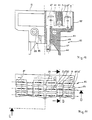
- FIGS. 1 and 4 show a cross section through a conventional add-on housing 1 and a plug insert 2 according to the invention used therein.
- the plug insert 2 has mounting flanges 26 which rest on bases 38 in the attachment housing 1 and are connected to the latter by means of screws 27 shown only by means of center lines.
- the plug insert 2 comprises a first part 4 inserted into the through opening 3 of the attachment housing 1, and a second part 5 lying outside the same and projecting beyond the open cross section of the attachment housing 1.
- the first part 4 merges in one piece into a base plate 6 of the second part 5 .
- This has a side frame part 7.
- Inserts 8 are fitted into the frame part.
- pairs of insertion openings 9 are provided, into which contact sockets 10 are inserted.
- the plug insert 2 of the form shown here has a first connection surface 13 with the insertion openings 9 for the contact inserts and two parallel connection surface parts 22, 23, which are coplanar and symmetrical to one another, with the insertion openings 19 for connection contacts, the first connection surface 13 and the second pads 22, 23 are directed opposite to each other.
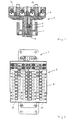
- FIGS. 2 and 5 details corresponding to those in FIGS. 1 and 4 are designated with the same reference numbers.
- the reference numbers are predominantly only entered in the enlarged representation according to FIG. 5.
- the top view of the add-on housing 1 can be seen, which has at its ends flanges 25 with through holes 24 for pushing through screws for fastening the housing to a switch cabinet housing or the like.
- fastening flanges 26 are screwed onto the base 38 in the through opening 3 by means of screws 27.
- Sheet metal parts are fastened on the end face to the plug insert 2, forming tabs 28, 29, one of which is equipped with a holding plate 30 and a clamping screw 31, while in the other only a threaded hole 32 can be seen. Earthing or protective contact conductors can be connected to these tabs.
- the plug insert 2, of which the second part 5 is visible is partly shown in view, partly with the cover part 14 being broken away.
- the peripheral frame part 7 is shown without breaking out.
- the conductor rails each have laterally broken-out contact edges 33, into which contact brackets 20 can be snapped in and can be used to produce a conductive contact between two adjacent conductor rails 11 lying in parallel.
- These contact brackets 20 comprise resilient conductor legs 34 lying in parallel. Four of these contact brackets can be seen in section in the cutaway representation previously discussed.
- the openings 18, 18 'for the clamping screws and the openings 19, 19' for inserting the conductor wires can be seen in the view. Between two rows of the openings mentioned, further openings 21 are arranged, into which the aforementioned contact brackets 20 can be inserted. In the view, four of the contact brackets 20 are shown with their handle parts 35 lying on top.
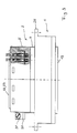
- FIGS. 3 and 6 corresponding details are given the same numbers as in the other figures. The major part of the details is only entered in the enlarged representation of FIG. 6.
- the attachment housing 1 with flanges 25 with the through holes 24 can be seen, in which the plug insert 2 is inserted as in the previously mentioned figures.
- This is inserted with its first part 4 in the through opening 3 of the attachment housing 1, and protrudes from the bottom of this.
- the upper wider second part 5 is shown in partial section.
- the through opening 3 has a central axis A.
- the holding plate 30 and the clamping screw 31 can be seen on the left.
- the second part 5 with the frame 7, in which the cover part 14 is inserted precisely recognize.
- the conductor rails 11 are inserted and held, on which the laterally broken contact edges 33 can be seen.
- the contact bracket 20 are inserted, which have a non-conductive handle part 35 and two resilient conductor legs 34, which are conductively connected to one another in a U-shape and are cast in the handle part 35.
- the free conductor legs 34 run against a wedge 37 in the base plate 6, which ensures that the legs 34 make conductive contact with the contact edges 33 of two conductor rails 11 lying parallel to one another.
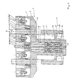
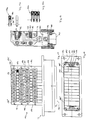
- Figures 7 and 10 and 8 and 11 are jointly described below. Individual reference numbers can only be found in one or the other of the figures described together.
- Figure 7 corresponds to a section along the section line AB from Figure 8
- Figure 10 corresponds to a section along the section line CD from Figure 11
- Figure 12 corresponds to a section along the section line AB from Figure 11.
- a plug insert 52 is shown partially (FIG. 10) or completely and inserted into a conventional add-on housing 51 (FIG. 7).
- the plug insert 52 has fastening flanges 76 which rest on bases 88 in the attachment housing 51 and are connected to the latter by means of screws 77.
- the plug insert 52 includes a in the through opening 53 of the Add-on housing 51 inserted first part 54, and a second part 55 lying outside of add-on housing 51 and projecting over its open cross-section.
- the lower section of the first part is formed by a contact insert 89, which is not shown in FIG.
- the first part 54 merges in one piece into the second part 55 in the sectional plane shown in FIG. 10.
- Openings 59 in the form of longitudinal recesses are provided in the plug insert 52, into which conductor rails 61 are inserted.
- Contact pins 60 are pushed onto these and crimped on at the bottom.
- the conductor rails 61 merge in one piece into connection contacts 67, 67 '. They also have middle contact tongues 62.
- the conductor rails 61 are punched out of sheet metal.
- the connection contacts 67, 67 ' end in open insertion openings 69, 69' for suitable flat plugs.
- the contact tongues 83 are in the region of insertion openings 71 for contact brackets which will be shown later.
- Longitudinal bores 98 are formed in the plug insert 52, through which rivets 99 can be pushed for connecting several disk-shaped parts of the plug insert.
- the plug insert 52 of the form shown here has a connection surface 63 with the openings 59 for the contact inserts and two connection surface parts 72, 73 lying parallel thereto, which are coplanar and symmetrical to one another, with the insertion openings 69 for connection contacts, the connection surfaces 63 and the connection surfaces 72, 73 lie opposite to each other.
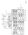
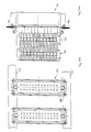
- FIGS. 8 and 11 details corresponding to those in FIGS. 7 and 10 are designated by the same reference numbers.
- the plug insert 52 is shown in a top view, the attachment housing 51, into which the plug insert 52 is inserted, being visible in FIG.
- the attachment housing 51 shows at its ends flanges 75 with through holes 74 for inserting screws with which the attachment housing 51 on a control cabinet housing or the like can be screwed.
- fastening flanges 76 of the plug insert 52 are screwed onto the aforementioned bases 88 of the attachment housing by means of screws 77.
- FIG. 11 shows that the plug insert is made up of front-side washer bodies 56 ', 56' and further washer bodies 56 which are identical to one another.
- the designation disc body does not conflict with the fact that springs and grooves 96, 97 join into one another in the end faces.
- the insertion openings 69, 69 ' can be seen between the disk bodies, in which the connection contacts 67, 67', which are designed as tongue-shaped sheet metal parts, are free. Standard flat plugs can be attached to these.
- the insertion openings 71 into each of which the contact tongues 83 protrude at the end, lie outside the section plane shown in FIG. If a contact clip is inserted into one of these openings 71, adjacent pairs of connection contacts 67, 67 'are conductively connected to one another via the establishment of a conductive contact between the corresponding contact tongues 83, e.g. B. the designated with 1 - 1 connection contacts with the parallel contacts, to which the numbers 2 - 2 are to be assigned mutatis mutandis.
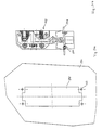
- FIG. 9 shows the plug insert 52 installed in the attachment housing 51 without any particular details, the first part 54 and the second part 55, which protrudes above, protruding from the through opening. It is indicated that the plug insert 52 as a whole is made up of washer bodies 56 of the same type with one another and two front washer bodies 56 ', 56 ", each of which is the entire height of the first and second Include parts. In contrast, the part of the plug insert for contact pins or contact sockets protruding from the through opening is in one piece. The central axis A of the through opening is particularly marked.
- FIG. 12a shows a section through the upper part of the second part 55 of a plug insert.
- the insertion openings 71 can be seen, these being located between individual disk bodies 56, which, viewed in this sectional plane as well, engage one another with mold engagement means 94, 95, without this contradicting the designation as a disk body.
- the contact tongues 83 with openings 86 each lie on the end face in the insertion openings 71.
- Parts of the contact bracket 70 shown in detail in FIG. 12b engage in the openings 86 and have a non-conductive handle part 85 and two resilient conductor legs 84 which are connected to one another in a U-shaped manner and are cast on the handle 85.
- expressions 87 of the conductor legs 84 snap into the openings 86 of the contact tongues 83. In this way, conductive contact is established between adjacent pairs of connection contacts 67, 67 '.
- FIGS. 13a and 13b are described together below.
- the reference numbers mentioned are increased by 100 compared to corresponding parts from the illustration in FIGS. 1 and 4.
- FIGS. 13a and 13b show a cross section through a conventional add-on housing 101a between 101b and a plug insert 102 according to the invention used therein.
- the plug insert 102 has screwed-on fastening flanges 126 which rest on bases 138a and 138b in the add-on housing 101 and are connected to the latter by means of screws 127.
- the bases 138a according to FIG. 13a are located to the front on the plug side in the housing 101a; the mounting tabs 126 are for assembly and screwing the plug insert 102 on them from behind.
- the bases 138b according to FIG. 13b are set back from the plug side deeper in the housing 101b; The assembly of the plug insert 102 and its screwing can be done from the front.
- the plug insert 102 comprises a first part 104 inserted into the through opening 103 of the attachment housing 101, and a second part 105 lying outside the same and fitting into the open cross section of the attachment housing 101.
- the first part 104 merges in one piece into a base plate 106 of the second part 105 .
- This has a lateral frame part 107.
- a cover part 114 is fitted into the frame part.
- openings not shown in pairs, are provided, in which contact sockets are inserted. These are in contact with conductor rails 111, which are divided into first contact tongues 112 and second contact tongues 112 ', only half of the second part being numbered.
- the conductor rails 111 are held between the base plate 106 and the cover part 114.
- the previously mentioned parts are each provided in a symmetrical design with respect to a central plane E of the second part 105.
- the cover part 114 inserted into the frame part 107 of the second part 105 has multiple openings and is made in one piece. This holds four units of connection contacts, each of which consists of a holding plate 115, 115 ', a clamping screw 116, 116' screwed therein and a movable clamping tab 117, 117 '.
- the clamping screw 116, 116 ' is tightened, the clamping tab 117, 117' lies against one of the contact tongues 112, 112 ', so that a conductor can be clamped here.
- Screw openings 118, 118 ' are provided in the cover part 114 for adjusting the clamping screws, and further insertion openings 119, 119' are provided for inserting conductor wires.
- the plug insert 102 in the form shown here has a first connection surface 113 with the openings for the contact inserts and two second connection surface parts 122, 123 which form an angle of 90 ° with respect to one another are coplanar and symmetrical, with the insertion openings 119 for connecting contacts. Plug inserts of this type may have to be pushed completely through an attachment housing while tipping to the side.
- FIG. 14 corresponding details are designated with reference numbers increased by 100 compared to FIGS. 2 and 5.
- the side view of the add-on housing 101 can be seen, which has at its ends flanges 125 for fastening the housing to a control cabinet housing or the like.
- the plug insert 102, of which the second part 105 is visible, is shown partly in view, partly with the cover part 114 being broken away.
- the peripheral frame part 107 is shown without breaking out.
- Parallel conductor rails 111 which branch into contact tongues 112, 112 ', can be seen below the broken-out area.
- clamping tabs 117, 117 'and clamping screws 116, 116' can be seen, only half of the illustration being numbered.
- the conductor rails each have laterally broken-out contact edges 133, into which contact clips 120 can be snapped in and can be used to produce a conductive contact between two adjacent conductor rails 111 lying in parallel.
- These contact brackets 120 comprise resilient conductor legs 134 lying in parallel. Four of these contact brackets can be seen in section in the previously discussed broken away representation.
- the openings 118, 118 'for the clamping screws and the openings 119, 119' for the insertion of the conductor wires can be seen. Between two rows of the openings mentioned, further openings 121 are arranged, into which the aforementioned contact brackets 120 can be inserted. In the view, four of the contact brackets 120 are shown with their handle parts 135 lying above.
- FIG. 15 Corresponding details are shown in FIG. 15 with reference numbers increased by 100 compared to FIGS. 2 and 5.
- the add-on housing 101 with flanges 125 with the through holes 124 can be seen, in which the plug insert 102 is inserted. This is inserted with its first part 104 into the through opening 103 of the add-on housing 101, and protrudes from the bottom thereof. The upper second part 105 does not extend in width beyond the cross section of the through opening 103.
- fastening flanges 126 screwed onto the plug insert are screwed onto the base 138 in the through opening 103 by means of screws 127.
- Sheet metal parts are fastened on the end face to the plug insert 102 and form a tab 128 which is equipped with a holding plate 130 and a clamping screw 131. Earthing or protective contact conductors can be connected to this tab.
- the plug insert 152 shows a plug insert 152 inserted into a conventional add-on housing 151.
- the plug insert 152 has screwed-on fastening flanges 176 which rest on bases 188 in the add-on housing 151 and are connected to the latter by means of screws 177.
- the bases 188 do not have threaded holes but through holes, while the screwed-on fastening flanges 176 are made of reinforced material and have threaded holes so that they can be screwed from the plug side.
- the plug insert 152 comprises a first part 154 inserted into the through opening 153 of the attachment housing 151, as well as a second part 155 which lies outside the attachment housing 151 and does not go beyond the open cross section thereof.
- the first part 154 merges in one piece into the second part 155. Longitudinal recesses are provided in the plug insert 152, are inserted in the conductor rails 161. On this, not shown plug contacts are pushed and z. B. crimped.
- the conductor rails 161 merge in one piece into connection contacts 167, 167 '. They also have middle contact tongues 183.
- the conductor rails 161 are punched out of sheet metal material.
- the connection contacts 167, 167 ' end in open insertion openings 169, 169' for suitable flat plugs.
- the contact tongues 183 are in the region of insertion openings 171 for contact brackets which will be shown later.
- the plug insert 152 of the form shown here has a first connection surface 163 with the openings for the contact inserts and two second connection surface parts 172, 173, which are coplanar and symmetrical to one another, with the insertion openings 169 for connection contacts, the connection surface 163 and the connection surfaces 172, 173 at an angle of 90 ° to each other.
- the plug insert 152 is shown in a side view, the attachment housing 151, into which the plug insert 152 is inserted, also being visible.
- the attachment housing 151 shows at its ends flanges 175 with which the attachment housing 151 can be screwed to a control cabinet housing or the like. It can be seen that the plug insert is constructed from first end-side washer bodies 156 ', 156 "and further washer bodies 156 which are identical to one another.
- washer body does not preclude the fact that in the end faces springs and grooves 196, 197 interlock.
- connection contacts 167, 167' which are designed as tongue-shaped sheet metal parts, stand free be plugged on.
- the plug insert 152 is shown installed in the mounting housing 151, the second part 155, which protrudes from the top of the through opening, does not extend in width beyond the cross section of the through opening.
- Screwed-on fastening flanges 176 of the plug insert 152 are screwed onto the aforementioned bases 188 of the attachment housing in the through opening 153 of the attachment housing 151 by means of screws 177.
- On the face side of the plug insert 152 these have metal tabs 79, against each of which a holding plate 180 can be pressed by means of a screw 181, grounding or protective contact conductors being able to be clamped between the parts mentioned.
- the plug insert 152 as a whole is made up of washer bodies 156 of the same type with one another and two front washer bodies 156 ', 156 "which each comprise the entire height of the first and second parts.
- the contact insert for contact pins or contact sockets protruding from the through opening below in contrast, is in one piece.
- FIG. 19a shows a section and a side view of a contact clip 170, which has a non-conductive handle part 185 and two resilient conductor legs 184, which are conductively connected to one another in a U-shape and are cast in on the handle part 185.
- the conductor legs 184 have expressions 187, their locking function has already been explained.
- FIG. 19b shows a modified contact bracket 170 'which accommodates three pairs of conductor limbs 184 in a single grip part 185, each of which is connected to one another in a U-shape. This enables conductive connections to be made between four pairs of connection contacts at once.
- FIG. 20a shows how two plug inserts 152 arranged parallel to one another are screwed onto parallel mounting rails 201, 202, the connection surfaces 163 of the plugs being recognizable.
- FIG. 20b shows the same details as in FIG. 20a in cross section through the carrier rails 201, 202. In this case, the coplanar mating surface parts 172, 173 are recognizable.
- FIG. 21a shows a sheet metal wall part 251 with a hole cutout 252 and screw holes 253 for inserting and screwing on a plug insert.
- 21b shows a plug insert 152 in vertical section, which is inserted in the sheet metal wall part 251 and fastened by means of screws 254.
- FIG. 22 shows a plug insert 352 and an attachment housing 51 in a similar construction as in FIG. 7, but here the second connection surfaces 372, 373 are inclined at an angle with respect to the first connection surface 363 and offset parallel to one another.
- FIG. 23 shows a plug insert 452 and an attachment housing 51 in a construction similar to that in FIG. 7, but there are the second connection surfaces 472, 473 are symmetrically inclined relative to the first connection surface 463 by an equally large angle, so that they form a roof shape with one another.
- FIG. 24 shows a plug insert 552 in an attachment housing 51 similar to that in FIG. 16.
- the second connection surfaces 572, 573 are coplanar and inclined by an angle deviating from 90 degrees with respect to the first connection surface 563.
- FIG. 25 shows a plug insert 652 and an attachment housing 51 in a similar design to that shown in FIG. 16.
- one of the two second connection surfaces 672 is arranged opposite the first connection surface 663, while the second connection surface 673 forms an angle of 90 ° with respect to the first connection surface 663.
Abstract
Description
Vielpoliger Steckereinsatz - insbesondere zum Einbau in ein Steckergehäuse, wobei am Steckereinsatz Befestigungsflansche und am Steckergehäuse Befestigungssockel vorgesehen sind - wobei der Steckereinsatz einen ersten Teil umfaßt, der eine erste Anzahl von in Einstecköffnungen sitzenden Kontakteinsätzen aufweist, und einen zweiten Teil umfaßt, der eine zweite, gegenüber der ersten mehrfache Anzahl von in Anschlußöffnungen sitzenden Anschlußkontakten aufweist, wobei jeder Kontakteinsatz im ersten Teil zumindest mit zwei Anschlußkontakten im zweiten Teil dauerhaft leitend verbunden ist, und im zweiten Teil jeweils zwischen zwei benachbarten Gruppen von zumindest zwei Anschlußkontakten, die jeweils mit einem Kontakseinsatz im ersten Teil dauerhaft leitend verbunden sind, eine Öffnung vorgesehen ist, in die ein Kontaktbügel einklemmbar ist. der eine leitende Verbindung zwischen den beiden benachbarten Gruppen von zumindest zwei Anschlußkontakten herstellt.Multipole plug insert - in particular for installation in a plug housing, with mounting flanges being provided on the plug insert and fastening bases on the plug housing - the plug insert comprising a first part which has a first number of contact inserts located in insertion openings, and a second part which comprises a second, compared to the first multiple number of connection contacts seated in connection openings, each contact insert in the first part being permanently conductively connected to at least two connection contacts in the second part, and in the second part in each case between two adjacent groups of at least two connection contacts, each with a contact insert in the the first part are permanently connected, an opening is provided into which a contact clip can be clamped. which establishes a conductive connection between the two adjacent groups of at least two connection contacts.
Steckereinsätze der obengenannten Art kommen im Bereich der industriellen Steuerung und Regelung vielfältig zum Einsatz. Sie werden dabei häufig zu mehreren in paralleler Anordnung in Schaltkästen zusammengefaßt. Der jeweilige Steckereinsatz bzw. das jeweilige Anbaugehäuse wird dabei so in den Schaltschrank eingesetzt, daß Steckkontakte - Stifte oder Buchsen - zur Verbindung mit einem Gegenstecker nach außen weisen, während auf der Innenseite über entsprechende Anschlußkontakte die gewünschte Verdrahtung erfolgt. Die Anschlußkontakte können als Schraubkontakte, Flachsteckkontakte, Krimpkontakte, federbelastete Klemmkontakte, Lötkontakte oder der Form von Termi-Point (Anschluß für Klemmschuh) oder Wire-Rap (Anschluß für Wickeltechnik) ausgebildet sein.Plug inserts of the type mentioned above are used in a variety of ways in the field of industrial control and regulation. They are often combined into several in a parallel arrangement in switch boxes. The respective plug insert or the respective add-on housing is inserted into the control cabinet in such a way that plug contacts - pins or sockets - point outwards for connection with a mating connector, while the desired wiring is carried out on the inside via corresponding connection contacts. The connection contacts can be screw contacts, flat plug contacts, crimp contacts, spring-loaded Clamp contacts, solder contacts or the form of termi-point (connection for clamping shoe) or wire-rap (connection for winding technology).
Es besteht hierbei häufig die Forderung, daß ein Kontaktstift oder eine Kontaktbuchse mehrfach belegt wird, d. h. es entsteht die Notwendigkeit, eine mehrfache Verdrahtung für jeden Kontaktstift oder jede Kontaktbuchse zu ermöglichen. Die Möglichkeit, dies jeweils mit einem einzigen Anschlußkontakt zu verwirklichen, ist äußerst unpraktisch, insbesondere bei Lötverbindungen nahezu ausgeschlossen. Hinzu kommt, daß eine solche Art der mehrfachen Belegung nach VDE und den Vorschriften der Deutschen Bundesbahn unzulässig ist, für die Industrie gelten im wesentlichen entsprechende Werksnormen; zumindest wird eine solche Belegung nicht praktiziert. Ausschließlich bei Lötverbindungen können im Fall von Steuerströmen, nicht jedoch bei Leistungsströmen Doppelbelegungen eines Anschlußkontaktes vorkommen, wenn die Anschlußdrähte zuvor mit Lötösen versehen werden.There is often the requirement that a contact pin or a contact socket is occupied several times, i. H. there is a need to allow multiple wiring for each contact pin or socket. The possibility of realizing this with a single connection contact is extremely impractical, especially for soldered connections almost impossible. In addition, such a type of multiple assignment according to VDE and the regulations of the German Federal Railways is not permitted. For industry, the relevant company standards essentially apply; at least such an assignment is not practiced. In the case of control currents, but not in the case of power currents, double assignment of a connection contact can occur only with soldered connections if the connection wires are provided with soldering lugs beforehand.
Aus der DE-A-35 22 797 ist ein vielpoliger Steckereinsatz der genannten Art bekannt, bei dem jeweils ein Steckerkontaktelement mit einer Mehrzahl - d. h. insbesondere vier - Leitungsanschlußelementen verbunden ist. Brückenglieder können auf benachbarte Leitungsanschlußelemente so aufgesteckt werden, daß sämtliche Leitungsanschlußelemente zweier benachbarter Steckerkontaktelemente elektrisch leitend verbunden werden und damit auf gleichem Potential liegen. Von den zuvor vefügbaren - insgesamt acht - Leitungsanschlußelementen zweier benachbarter Steckerkontaktelemente sind damit zwei belegt, so daß nunmehr nur eine reduzierte Anzahl - sechs - für anzuschließende Leiter frei bleibt. Beim ausgeführten Steckereinsatz gehen also 25 % der zur Verfügung stehenden Leitungsanschlußelemente beim Herstellen einer Brückenschaltung verloren. Nachteilig ist ferner, daß das Herstellen einer Brückenschaltung bei bereits vollständig belegten Leitungsanschlußelementen nicht möglich ist.From DE-A-35 22 797 a multi-pole plug insert of the type mentioned is known, in which in each case one plug contact element is connected to a plurality - ie in particular four - line connection elements. Bridge elements can be plugged onto adjacent line connection elements in such a way that all line connection elements of two adjacent plug contact elements are connected in an electrically conductive manner and are therefore at the same potential. Two of the previously available - a total of eight - line connection elements of two adjacent plug contact elements are thus occupied, so that now only a reduced number - six - remains free for conductors to be connected. When the connector is used, 25% of the available line connection elements are lost when a bridge circuit is made. Another disadvantage is that the manufacture of a bridge circuit with fully occupied Line connection elements is not possible.
Hiervon ausgehend ist es Aufgabe der vorliegenden Erfindung, einen Steckereinsatz der eingangs genannten Art bereitzustellen, der eine variable mehrfache Belegung jeden Kontaktstiftes oder jeder Kontaktbuchse zuläßt, ohne das Anschließen zu erschweren oder die Funktion und die Betriebssicherheit zu beeinträchtigen.Proceeding from this, it is an object of the present invention to provide a plug insert of the type mentioned at the outset which permits a variable multiple assignment of each contact pin or contact socket without complicating the connection or impairing the function and the operational reliability.
Die Lösung hierfür besteht darin, daß die Öffnung derart ausgebildet ist, daß bei eingeklemmten Kontaktbügel die Anschlußkontakte unbelegt bleiben, so daß diese bei eingeklemmtem Kontaktbügel eine Anschlußmöglichkeit für Anschlußdrähte behalten.The solution to this is that the opening is designed such that when the contact clip is clamped in, the connection contacts remain unoccupied, so that they retain a connection possibility for connecting wires when the contact clip is clamped in.
In günstiger Ausführung ist vorgesehen, daß jeder Steckkontakt im ersten Teil jeweils gerade mit zwei Anschlußkontakten im zweiten Teil dauerhaft leitend verbunden ist. Dies entspricht dem am häufigsten auftreten Bedarf, so daß im weiteren auch nur noch darauf Bezug genommen wird. Abweichend davon ist es auch möglich, daß jeder Steckkontakt im ersten Teil mit einer größeren Anzahl, z. B. jeweils vier Anschlußkontakten, im zweiten Teil dauerhaft leitend verbunden ist, wenn ein entsprechender Bedarfsfall vorliegt. Erfindungsgemäß wird die Möglichkeit geschaffen, wahlweise Leiterverbindungen zwischen einer größeren Anzahl von Anschlußkontakten untereinander mittels geeigneter Kontaktbügel herzustellen. Auf Kontaktbügel dieser Art wird später noch eingegangen.In a favorable embodiment it is provided that each plug-in contact in the first part is in each case permanently conductively connected to two connection contacts in the second part. This corresponds to the need that occurs most frequently, so that in the following it will only be referred to. Deviating from this, it is also possible that each plug contact in the first part with a larger number, for. B. four connection contacts each, is permanently conductively connected in the second part if there is a corresponding need. According to the invention, the possibility is created to selectively establish conductor connections between a larger number of connection contacts with one another by means of suitable contact clips. This type of contact bracket will be discussed later.
In günstiger Ausgestaltung umfaßt der erste Teil zwei parallele Reihen von Steckkontakten und der zweite Teil vier parallele Reihen von Anschlußkontakten von jeweils gleicher Anzahl. Hierbei wird in erster Linie an Anbaugehäuse für 6-, 10-, 16- oder 24-polige Stecker gedacht. Die erfindungsgemäße Idee ist jedoch auch auf solche Stecker zu übertragen, die beispielsweise nur eine Reihe von Steckkontakten im Bereich des ersten Teils und mehrere, insbesondere zwei Reihen von Anschlußkontakten im zweiten Teil aufweisen.In a favorable embodiment, the first part comprises two parallel rows of plug contacts and the second part four parallel rows of connection contacts, each of the same number. The main focus here is on add-on housings for 6, 10, 16 or 24-pin connectors. However, the idea according to the invention can also be applied to plugs which, for example, only have a number of plug contacts in the area of the first part and have several, in particular two rows of connection contacts in the second part.
Die Ausbildung des erfindungsgemäßen Steckereinsatzes besteht darin, daß im zweiten Teil jeweils zwischen zwei Gruppen von ständig leitend miteinander verbundenen Anschlußkontakten eine Öffnung vorgesehen ist, in die ein Kontaktbügel einklemmbar ist, der eine leitende Verbindung zwischen den zwei benachbarten Guppen von jeweils ständig miteinander leitend verbundenen Anschlußkontakten herstellt.The design of the plug insert according to the invention consists in that in the second part, an opening is provided between two groups of permanently conductively connected connection contacts, into which a contact clip can be clamped, which provides a conductive connection between the two adjacent groups of connection contacts which are always conductively connected to one another manufactures.
Anstelle federnder Kontaktbügel, die mit festen Kontaktkanten an Leitern zusammenwirken, können auch unelastische Kontaktstifte treten, die mit federnden Kontaktkanten der Leiter zusammenwirken.Instead of resilient contact brackets, which interact with fixed contact edges on conductors, inelastic contact pins can also occur, which interact with resilient contact edges of the conductors.
Hiermit ist es möglich, einem breiten Anforderungsprofil zu genügen, indem die Zahl der Anschlußmöglichkeiten für einen Kontaktstift oder eine Kontaktbuchse auf 4, 6, 8 usw. erhöht wird, indem durch die genannten Kontaktbügel jeweils Leiterbrücken hergestellt werden. Es ist allerdings darauf hinzuweisen, daß sich hierbei die Zahl der im Gegenstecker belegbaren ergänzenden Steckkontakte reduziert, d. h. ein Anteil der Steckkontakte liegt auf gleichem Potential.This makes it possible to meet a wide range of requirements by increasing the number of connection options for a contact pin or a contact socket to 4, 6, 8, etc., by producing conductor bridges in each case through the contact brackets mentioned. However, it should be noted that this reduces the number of additional plug contacts that can be assigned in the mating connector, ie. H. a proportion of the plug contacts is at the same potential.
Nach einer ersten, für die Montage günstigen Ausführung ist vorgesehen, daß der Steckereinsatz aus zumindest zwei Teilen besteht und dabei im zweiten Teil in einer Hauptteilungsebene senkrecht zu den Durchgangsöffnungen des Steckereinsatzes geteilt ist und entsprechende Ausnehmungen aufweist, in die Leiterelemente eingelegt werden können, die dann durch das Zusammensetzen der beiden Teile fixiert werden, und zur leitenden Verbindung der Steckkontakte mit den jeweiligen Anschlußkontakten dienen. Die aus nicht-leitendem Material bestehenden beiden Teile des zweiten Teils des Steckereinsatzes können über Klemmverbindungen oder über Klebeverbindungen gegeneinander gesichert werden.According to a first embodiment, which is favorable for assembly, it is provided that the plug insert consists of at least two parts and is divided in the second part in a main division plane perpendicular to the through openings of the plug insert and has corresponding recesses into which conductor elements can be inserted, which can then be inserted can be fixed by assembling the two parts, and serve for the conductive connection of the plug contacts with the respective connection contacts. The two made of non-conductive material Parts of the second part of the plug insert can be secured against one another by means of clamp connections or adhesive connections.
Nach einer anderen für die Montage günstigen Ausführung ist vorgesehen, daß der Steckereinsatz aus einer Vielzahl von Scheibenkörpern zusammengesetzt ist, die jeweils den ersten und zweiten Teil umfassen und deren Hauptteilungsebenen parallel zu den Durchgangsöffnungen des Steckereinsatzes liegen und die entsprechende Ausnehmungen aufweisen, zwischen denen jeweils miteinander leitend verbundene Steckkontakte und Anschlußkontakte eingelegt werden können, die dann durch das Zusammensetzen von jeweils zweien der Scheibenkörper gehalten werden. Die aus nicht-leitendem Material bestehende Vielzahl von Scheibenkörpern kann mittels Niet- oder Schraubverbindungen, die quer zu den Scheibenebenen durchgesteckt sind, auf einfache Weise miteinander verbunden werden.According to another embodiment which is favorable for assembly, it is provided that the plug insert is composed of a plurality of disk bodies, each of which comprises the first and second part and whose main parting planes are parallel to the through openings of the plug insert and have the corresponding recesses, between which each other Conductively connected plug contacts and connection contacts can be inserted, which are then held by the assembly of two of the disk body. The large number of disc bodies made of non-conductive material can be connected to one another in a simple manner by means of rivet or screw connections which are pushed through transversely to the disc planes.
In einer bevorzugten ersten grundsätzlichen Ausführung ist vorgesehen, daß die Aufsichtsfläche des zweiten Teils über den Querschnitt des ersten Teils senkrecht zur Einsteckrichtung auskragt, hierbei ist es besonders vorteilhaft, wenn die mit Einstecköffnungen für die Kontakteinsätze versehene erste Anschluß fläche einerseits und die mit Einstecköffnungen für die Anschlußkontakte versehenen zweiten Anschlußflächen andererseits zueinander parallel sind und in entgegengesetzte Richtungen weisen. In weiterer vorteilhafter Ausbildung ist vorgesehen, daß die zweiten Anschlußflächen hierbei koplanar sind.In a preferred first basic embodiment it is provided that the supervisory surface of the second part protrudes perpendicular to the insertion direction over the cross section of the first part, in this case it is particularly advantageous if the first connection surface provided with insertion openings for the contact inserts on the one hand and the insertion openings for the Connections provided second pads on the other hand are parallel to each other and point in opposite directions. In a further advantageous embodiment it is provided that the second connection surfaces are coplanar.
Eine andere günstige Ausführung geht dahin, daß die Einstecköffnungen für die Kontakteinsätze versehene erste Anschlußfläche einerseits und die mit Einstecköffnungen für die Anschlußkontakte versehenen zweiten Anschlußflächen andererseits einen Winkel miteinander bilden. Hierbei ist es nach den Einbauverhältnissen möglich, daß die zweiten Anschlußflächen gegeneinander parallel versetzt sind oder daß die zweiten Anschlußflächen dachförmig zueinander und symmetrisch zur ersten Anschlußfläche liegen.Another inexpensive embodiment is that the insertion openings for the contact inserts provided on the one hand and the second connection surfaces provided with insertion openings for the contacts on the other hand form an angle. It is according to the installation conditions possible that the second pads are offset parallel to each other or that the second pads are roof-shaped to each other and symmetrical to the first pad.
Bei einem Steckereinsatz der genannten Art zum Einbau in ein Steckergehäuse mit einer Durchgangsöffnung zur Aufnahme des Steckereinsatzes ist vorteilhafterweise vorgesehen, daß der erste Teil in den Innenquerschnitt der Durchgangsöffnung einsetzbar ist und der zweite Teil sich außerhalb der Durchgangsöffnung an den ersten anschließt und über den Innenquerschnitt der Durchgangsöffnung auskragt.In the case of a plug insert of the type mentioned for installation in a plug housing with a through opening for receiving the plug insert, it is advantageously provided that the first part can be inserted into the inner cross section of the through opening and the second part adjoins the first outside the through opening and via the inner cross section of the Through opening protrudes.
Mit seinem ersten Teil ist ein solcher Steckereinsatz in ein übliches Steckergehäuse, insbesondere ein Anbaugehäuse, einsetzbar, so daß in dieser Hinsicht keine besondere Anpassung der Umgebung des Steckereinsatzes erfolgen muß. Der Steckereinsatz kann in seinem ersten Teil in bekannter Weise mit Kontaktstiften oder Kontaktbuchsen bestückt werden. Durch die erfindungsgemäße Ausbildung des zweiten Teils des Steckereinsatzes erhält jeder Kontaktstift bzw. jede Kontaktbuchse die Möglichkeit einer mehrfachen gesonderten Belegung mit Anschlußdrähten. Durch die verbreiterte Ausgestaltung des zweiten Teils des Steckereinsatzes haben die entsprechenden Anschlußkontakte übliche Abmessungen, insbesondere übliche Abstände untereinander, so daß eine sehr günstige Zugangsmöglichkeit gegeben ist.With its first part, such a plug insert can be inserted into a conventional plug housing, in particular an add-on housing, so that in this respect no special adaptation of the surroundings of the plug insert is necessary. The first part of the plug insert can be equipped with contact pins or contact sockets in a known manner. The inventive design of the second part of the plug insert gives each contact pin or contact socket the possibility of multiple separate assignment with connecting wires. Due to the widened configuration of the second part of the plug insert, the corresponding connection contacts have the usual dimensions, in particular the usual distances between them, so that there is a very favorable access option.
Ausgehend von einer üblicherweise länglich rechteckigen Form der Steckereinsätze und der passenden Anbaugehäuse ist in günstiger Ausgestaltung vorgesehen, daß erster und zweiter Teil des Stekkereinsatzes im wesentlichen gleiche Länge haben, so daß der zweite Teil jeweils seitlich in der Breite über das Anbaugehäuse auskragt. Mehrere in einem Schaltschrankgehäuse eingebaute Anbaugehäuse für die erfindungsgemäßen Steckereinsätze sind hiernach auf einen vergrößerten seitlichen Abstand zu setzen, können jedoch in mehreren Reihen dieser Art mit unverändertem üblichen Abstand ihrer Stirnseiten zueinander gesetzt werden.Starting from a usually elongated rectangular shape of the plug inserts and the matching attachment housing, it is provided in a favorable embodiment that the first and second part of the plug insert have essentially the same length, so that the second part projects laterally in width across the attachment housing. There are several built-in housings for the plug inserts according to the invention installed in a control cabinet housing to set an increased lateral distance, but can be placed in several rows of this type with the usual usual distance of their end faces to each other.
Durch die Formgebung des erfindungsgemäßen Steckereinsatzes muß sein Einsetzen in ein passendes standardmäßiges Anbaugehäuse von hinten erfolgen. Bevorzugt ebenfalls von hinten, bezogen auf das Anbaugehäuse, erfolgt das Verschrauben des Steckereinsatzes gegenüber demselben. Hieraus ergibt sich, daß das Anschließen der Verkabelung sinnvollerweise am separaten Steckereinsatz erfolgt, der danach von der Verkabelungsseite her in das - gegebenenfalls bereits im Schaltschank montierte - Anbaugehäuse eingesetzt wird.Due to the shape of the plug insert according to the invention, it must be inserted into a suitable standard mounting housing from behind. Also preferably from behind, based on the add-on housing, the plug insert is screwed relative to the same. It follows from this that the wiring is expediently connected to the separate plug insert, which is then inserted from the wiring side into the attachment housing, which may already be installed in the control cabinet.
In einer vorteilhaften alternativen grundsätzlichen Ausgestaltung ist vorgesehen, daß der Querschnitt des zweiten Teils in Richtung seiner Einstecköffnungen etwa mit dem Querschnitt des ersten Teils senkrecht zu dessen Einstecköffnungen übereinstimmt.In an advantageous alternative basic embodiment it is provided that the cross section of the second part in the direction of its insertion openings corresponds approximately to the cross section of the first part perpendicular to its insertion openings.
Hierbei ist es in günstiger Ausgestaltung möglich, daß die mit den Öffnungen für die Steckkontakte versehene erste Anschlußfläche des ersten Teils gegenüber den mit den Anschlußöffnungen für die Anschlußkontakte versehenen zweiten Anschlußflächen einen Winkel miteinander bilden. Hierbei ist es möglich, daß die erste Anschlußflächen einerseits und die zweiten Anschlußflächen andererseits einen Winkel von 90° miteinander bilden, wobei die Anschlußflächen zueinander koplanar sind oder daß die erste Anschlußfläche einerseits und die zweten Anschlußflächen andererseits einen zwischen 90° und 180° liegenden Winkel miteinander bilden.In a favorable embodiment, it is possible for the first connection surface of the first part provided with the openings for the plug contacts to form an angle with one another with respect to the second connection surfaces provided with the connection openings for the connection contacts. It is possible that the first connection surfaces on the one hand and the second connection surfaces on the other hand form an angle of 90 ° with one another, the connection surfaces being coplanar with one another or that the first connection surface on the one hand and the second connection surfaces on the other hand form an angle between 90 ° and 180 ° with one another form.
Bei einem Steckereinsatz der vorgenannten Art zum Einbau in ein Steckergehäuse mit einer Durchgangsöffnung zur Aufnahme des Steckereinsatzes ist vorteilhafterweise vorgesehen, daß der erste Teil in den Innenquerschnitt der Durchgangsöffnung einsetzbar ist und der zweite Teil sich außerhalb der Durchgangsöffnung mit einem durch diese hindurchführbaren Querschnitt anschließt.With a plug insert of the aforementioned type for installation in a plug housing with a through opening for receiving the It is advantageously provided that the first part can be inserted into the inner cross section of the through opening and the second part adjoins outside the through opening with a cross section that can be passed through it.
Die vorgenannten Steckereinsätze sind aufgrund ihrer Formgebung wahlweise von vorne oder von hinten in ein Anbaugehäuse einsetzbar. Um die entsprechenden Befestigungsflansche ggfs. an den Sockeln im Einbaugehäuse vorbeizuführen, ist eine geringe Kippbewegung erforderlich. In bevorzugter Ausführung ist jedoch vorgesehen, daß bei einem Einführen von vorne die Befestigungsflansche auch vorne auf im Anbaugehäuse zurückgesetzten Sockeln aufliegen, während bei einem Einsetzen von hinten die Befestigungsflansche von hinten auf im Anbaugehäuse in üblicher Weise angeordneten Sockeln aufliegen. Die Verschraubung kann aber ungeachtet dessen wahlweise von vorne oder von hinten erfolgen, je nachdem, ob die Sockel mit einem Durchgangsloch und die verstärkten angeschraubten Flansche mit einem Gewindeloch versehen sind oder umgekehrt.Due to their shape, the aforementioned plug inserts can be inserted into an attachment housing either from the front or from the rear. A small tilting movement is required to guide the corresponding mounting flanges past the bases in the installation housing. In a preferred embodiment, however, it is provided that, when inserted from the front, the fastening flanges also rest on the front in the attachment housing, while when inserting from the rear, the fastening flanges rest on the base arranged in the attachment housing in the usual manner. Regardless of this, the screw connection can be carried out either from the front or from the rear, depending on whether the base is provided with a through hole and the reinforced screwed-on flanges are provided with a threaded hole or vice versa.
Neben der hier ausführlich beschriebenen Befestigung der Stekkereinsätze in Anbaugehäusen ist auch ein unmittelbares Einschrauben in Blechböden mit entsprechenden Montageöffnungen möglich, deren Querschnitt dem Innenquerschnitt eines Anbaugehäuses entspricht. Daneben ist auch eine Anbringung auf einzelnen parallelen Trägerschienen möglich, wobei bei der Befestigung von mehreren Steckereinsätzen nur die Lochabstände der Befestigungslöcher auf den Trägerschienen entsprechend gewählt werden muß.In addition to the fastening of the plug inserts in attachment housings described in detail here, it is also possible to screw directly into sheet metal shelves with corresponding mounting openings, the cross section of which corresponds to the inner cross section of an attachment housing. In addition, attachment to individual parallel carrier rails is also possible, with only the hole spacing of the fastening holes on the carrier rails having to be selected accordingly when fastening multiple plug inserts.
Bevorzugte Ausführungsbeispiele sind durch die Unteransprüche wiedergegeben.Preferred exemplary embodiments are represented by the subclaims.
Die Erfindung wird nachstehend anhand von Zeichnungen näher erläutert.
- Fig. 1
- zeigt einen erfindungsgemäßen Steckereinsatz - in einem Anbaugehäuse montiert - im Vertikalschnitt in einer ersten Ausführung;
- Fig. 2
- zeigt einen Steckereinsatz mit einem Anbaugehäuse nach Fig. 1 in Draufsicht auf das zweite Teil;
- Fig. 3
- zeigt einen Steckereinsatz mit einem Anbaugehäuse nach Fig. 1 in Seitenansicht;
- Fig. 4
- zeigt die Darstellung nach Fig. 1 in Vergrößerung auf das doppelte der wahren Größe;
- Fig. 5
- zeigt eine Einzelheit der Fig. 2, vergrößert auf das Doppelte der wahren Größe;
- Fig. 6
- zeigt eine Einzelheit der Fig. 3, ebenfalls vergrößert auf das Doppelte der wahren Größe;
- Fig. 7
- zeigt einen erfindungsgemäßen Steckereinsatz - in einem Anbaugehäuse montiert - in einer Stirnansicht mit Teilschnitten in einer zweiten Ausführung;
- Fig. 8
- zeigt einen Steckereinsatz mit einem Anbaugehäuse nach Fig. 7 in Draufsicht auf das zweite Teil;
- Fig. 9
- zeigt einen Steckereinsatz mit einem Anbaugehäuse nach Fig. 7 in Seitenansicht;
- Fig. 10
- zeigt einen Teil des Steckereinsatzes nach Fig. 7 im Halbschnitt in Vergrößerung auf das Doppelte der wahren Größe;
- Fig. 11
- zeigt eine Einzelheit nach Fig. 8 vergrößert auf das Doppelte der wahren Größe;
- Fig. 12
- zeigt eine Ausführung von Kontaktbügeln
- a montiert in einem Steckereinsatz im Längsschnitt
- b als Einzelheit im Längsschnitt und in Seitenansicht.
- Fig. 13
- zeigt einen erfindungsgemäßen Steckereinsatz - in einem Anbaugehäuse montiert - im Vertikalschnitt in einer dritten Ausführung
- a in einem üblichen Anbaugehäuse
- b in einem Anbaugehäuse mit zurückgesetztem Sockel zur inversen Montage
- Fig. 14
- zeigt einen Steckereinsatz mit einem Anbaugehäuse nach Fig. 13 in Seitenansicht mit Aufsicht auf die zweiten Anschlußflächen;
- Fig. 15
- zeigt einen Steckereinsatz mit einem Anbaugehäuse nach Fig. 13 in Draufsicht;
- Fig. 16
- zeigt einen erfindungsgemäßen Steckereinsatz - in einem Anbaugehäuse montiert - im Vertikalschnitt in einer vierten Ausführung;
- Fig. 17
- zeigt einen Steckereinsatz mit einem Anbaugehäuse nach Fig. 16 in Seitenansicht mit Aufsicht auf die zweiten Anschlußflächen;
- Fig. 18
- zeigt einen Steckereinsatz mit einem Anbaugehäuse nach Fig. 16 in Draufsicht;
- Fig. 19
- zeigt Ausführungen von Kontaktbügeln
- a im Schnitt und in Seitenansicht,
- b im Schnitt durch drei integrierte Kontaktbügel;
- Fig. 20
- zeigt erfindungsgemäße Steckereinsätze auf parallelen Tragschienen montiert
- a in Draufsicht,
- b in Seitenansicht;
- Fig. 21
- zeigt eine Montagemöglichkeit für erfindungsgemäße Steckereinsätze;
- a einen vorbereiteten Montageausschnitt in einer Blechwand
- b einen montierten Stecker im Vertikalschnitt;
- Fig. 22
- zeigt einen erfindungsgemäßen Steckereinsatz - in einem Anbaugehäuse montiert - in Seitenansicht mit Teilschnitten in einer fünften Ausführung mit parallel versetzten zweiten Anschlußflächen;
- Fig.23
- zeigt einen erfindungsgemäßen Steckereinsatz - in einem Anbaugehäuse montiert - in Seitenansicht mit Teilschnitten in einer sechsten Ausführung mit dachförmig geneigten zweiten Anschlußflächen;
- Fig. 24
- zeigt einen erfindungsgemäßen Steckereinsatz - in einem Anbaugehäuse montiert - in Seitenansicht mit Teilschnitten in einer siebten Ausführung mit gegenüber der ersten abgewinkelten zueinander koplanaren zweiten Anschlußflächen;
- Fig. 25
- zeigt einen erfindungsgemäßen Steckereinsatz - in einem Anbaugehäuse montiert - in Seitenansicht mit Teilschnitten in einer achten Ausführung mit unsymmetrisch zur ersten in verschiedene Richtungen weisenden zweiten Anschlußflächen;
- Fig. 1
- shows a connector insert according to the invention - mounted in an attachment housing - in vertical section in a first embodiment;
- Fig. 2
- shows a connector insert with an attachment housing of Figure 1 in plan view of the second part.
- Fig. 3
- shows a connector insert with an attachment housing of Figure 1 in side view.
- Fig. 4
- shows the representation of Figure 1 in enlargement to twice the true size.
- Fig. 5
- shows a detail of Figure 2, enlarged to twice the true size;
- Fig. 6
- shows a detail of Figure 3, also enlarged to twice the true size;
- Fig. 7
- shows a connector insert according to the invention - mounted in an attachment housing - in an end view with partial sections in a second embodiment;
- Fig. 8
- shows a connector insert with an attachment housing of Figure 7 in plan view of the second part.
- Fig. 9
- shows a connector insert with an attachment housing of Figure 7 in side view.
- Fig. 10
- shows a part of the connector insert of Figure 7 in half section in enlargement to twice the true size.
- Fig. 11
- shows a detail of Figure 8 enlarged to double the true size;
- Fig. 12
- shows a version of contact bracket
- a mounted in a plug insert in longitudinal section
- b as a detail in longitudinal section and in side view.
- Fig. 13
- shows a connector insert according to the invention - mounted in an attachment housing - in vertical section in a third embodiment
- a in a conventional junction box
- b in an add-on housing with recessed base for inverse mounting
- Fig. 14
- shows a connector insert with an attachment housing of Figure 13 in side view with a view of the second pads.
- Fig. 15
- shows a connector insert with an attachment housing according to Fig. 13 in plan view;
- Fig. 16
- shows a connector insert according to the invention - mounted in an attachment housing - in vertical section in a fourth embodiment;
- Fig. 17
- shows a connector insert with an attachment housing according to Figure 16 in side view with a view of the second connection surfaces.
- Fig. 18
- shows a connector insert with an attachment housing according to Fig. 16 in plan view;
- Fig. 19
- shows versions of contact brackets
- a in section and in side view,
- b on average through three integrated contact clips;
- Fig. 20
- shows connector inserts according to the invention mounted on parallel mounting rails
- a in top view,
- b in side view;
- Fig. 21
- shows a mounting option for connector inserts according to the invention;
- a a prepared assembly cutout in a sheet metal wall
- b an assembled connector in vertical section;
- Fig. 22
- shows a connector insert according to the invention - mounted in an attachment housing - in side view with partial sections in a fifth embodiment with parallel offset second connection surfaces;
- Fig. 23
- shows a plug insert according to the invention - mounted in an attachment housing - in side view with partial sections in a sixth embodiment with roof-shaped inclined second connection surfaces;
- Fig. 24
- shows a connector insert according to the invention - mounted in an attachment housing - in side view with partial sections in a seventh embodiment with the first angled mutually coplanar second connection surfaces;
- Fig. 25
- shows a connector insert according to the invention - mounted in an attachment housing - in side view with partial sections in an eighth embodiment with asymmetrical to the first second connection surfaces pointing in different directions;
Nachstehend sind jeweils die Figuren 1 und 4, 2 und 5 sowie 3 und 6 gemeinsam beschrieben. Die Mehrzahl der angesprochenen Bezugsziffern findet sich jeweils nur in der vergrößerten Darstellung der Figuren 4, 5 und 6.Figures 1 and 4, 2 and 5 and 3 and 6 are described together below. The majority of the reference numbers mentioned can only be found in the enlarged representation of FIGS. 4, 5 and 6.
In den Figuren 1 und 4 ist ein Querschnitt durch ein übliches Anbaugehäuse 1 und einen darin eingesetzten erfindungsgemäßen Steckereinsatz 2 gezeigt. Der Steckereinsatz 2 hat Befestigungsflansche 26, die auf Sockeln 38 im Anbaugehäuse 1 aufliegen und mittels nur durch Mittel linien dargestellter Schrauben 27 mit diesem verbunden sind. Der Steckereinsatz 2 umfaßt ein in die Durchgangsöffnung 3 des Anbaugehäuses 1 eingesetztes erstes Teil 4, sowie ein außerhalb desselben liegendes, über den offenen Querschnitt des Anbaugehäuses 1 auskragendes zweites Teil 5. Das erste Teil 4 geht einstückig in eine Grundplatte 6 des zweiten Teils 5 über. Diese weist ein seitliches Rahmenteil 7 auf. In das Rahmenteil eingepaßt sind Einsätze 8. Im ersten Teil 4 sind paarweise Einstecköffnungen 9 vorgesehen, in welche Kontaktbuchsen 10 eingeschoben sind. Diese sind mit Leiterschienen 11 in Kontakt, die sich nach hinten in erste Kontaktzungen 12 und zweite Kontaktzungen 12' teilen. Die Leiterschienen 11 sind zwischen der Grundplatte 6 und den Einsätzen 8 gehalten. Diese Teile können miteinander verklemmt sein. Die bisher genannten Teile sind jeweils in symmetrischer Ausführung zu einer Mittelebene E vorgesehen, wobei zwei Hälften des ersten Teils 4 und der Grundplatte 6 mittig miteinander verklebt sind. In das Rahmenteil 7 des zweiten Teils 5 ist auf die Einsätze 8 ein vielfach durchbrochenes Deckelteil 14 eingesetzt, das einstückig ausgeführt ist. Dieses hält vier Einheiten von Anschlußkontakten, die jeweils aus einer Halteplatte 15, 15', einer darin eingedrehten Klemmschraube 16, 16' und einer beweglichen Klemmlasche 17, 17' betehen. Beim Anziehen der Klemmschraube 16, 16' legt sich die Klemmlasche 17, 17' gegen eine der Kontaktzungen 12, 12', so daß hier ein Leiter festgeklemmt werden kann. Zur Verstellung der Klemmschrauben sind im Deckelteil 14 Schraubenöffnungen 18, 18' vorgesehen, zum Einstecken von Leiterdrähten Einstecköffnungen 19, 19'. Es sind weiterhin Kontaktbügel 20 erkennbar, deren Form und Funktion anhand der weiteren Figuren erläutert werden wird. Der Steckereinsatz 2 der hier gezeigten Form weist eine erste Anschlußfläche 13 mit den Einstecköffnungen 9 für die Kontakteinsätze und zwei dazu parallel liegende zweite Anschlußflächenteile 22, 23, die zueinander koplanar und symmetrisch sind, mit den Einstecköffnungen 19 für Anschlußkontakte auf, wobei die erste Anschlußfläche 13 und die zweiten Anschlußflächen 22,23 einander entgegengesetzt gerichtet liegen.FIGS. 1 and 4 show a cross section through a conventional add-on
In den Figuren 2 und 5 sind entsprechende Einzelheiten wie in den Figuren 1 und 4 mit gleichen Bezugziffern bezeichnet. Die Bezugsziffern sind überwiegend nur in der vergrößerten Darstellung nach Figur 5 eingetragen. In Draufsicht ist das Anbaugehäuse 1 erkennbar, das an seinen Enden Flansche 25 mit Durchgangslöchern 24 zum Durchstecken von Schrauben zum Befestigen des Gehäuses an einem Schaltschrankgehäuse oder dergleichen aufweist. In der Durchgangsöffnung 3 des Anbaugehäuses 1 sind Befestigungsflansche 26 mittels Schrauben 27 auf die Sockel 38 in der Durchgangsöffnung 3 aufgeschraubt. Stirnseitig am Steckereinsatz 2 sind Blechteile befestigt, die Laschen 28, 29 bilden, von denen eine mit einem Halteblech 30 und einer Klemmschraube 31 bestückt ist, während in der anderen nur ein Gewindeloch 32 erkennbar ist. An diesen Laschen können Erdungs- bzw. Schutzkontaktleiter angeklemmt werden. Der Steckereinsatz 2, von dem das zweite Teil 5 sichtbar ist, ist teils in Ansicht dargestellt, teils unter Wegbrechen des Deckelteils 14. Das umlaufende Rahmenteil 7 ist ohne Ausbrechung dargestellt.In FIGS. 2 and 5, details corresponding to those in FIGS. 1 and 4 are designated with the same reference numbers. The reference numbers are predominantly only entered in the enlarged representation according to FIG. 5. The top view of the add-on
Unter dem ausgebrochenen Bereich sind parallele Leiterschienen 11 erkennbar, die sich in Kontaktzungen 12, 12' verzweigen. Jeweils in Zuordnung zu diesen sind Klemmlaschen 17, 17' und Klemmschrauben 16, 16' erkennbar. Die Leiterschienen haben jeweils seitlich ausgebrochene Kontaktkanten 33,in die Kontaktbügel 20 einrastbar sind und unter Herstellung eines leitenden Kontaktes zwischen zwei parallel liegender benachbarter Leiterschienen 11 eingesetzt werden können. Diese Kontaktbügel 20 umfassen parallel liegende federnde Leiterschenkel 34. Vier dieser Kontaktbügel sind in der zuvor diskutierten weggebrochenen Darstellung geschnitten dargestellt erkennbar.Parallel conductor rails 11, which branch into
In der Ansicht sind die Öffnungen 18, 18' für die Klemmschrauben sowie die Öffnungen 19, 19' für das Einstecken der Leiterdrähte erkennbar. Jeweils zwischen zwei Reihen der genannten Öffnungen sind weitere Öffnungen 21 angeordnet, in die die zuvor genannten Kontaktbügel 20 eingeschoben werden können. In der Ansicht sind vier der Kontaktbügel 20 mit ihren obenliegenden Griffteilen 35 dargestellt.The
In den Figuren 3 und 6 sind entsprechende Einzelheiten mit den gleichen Ziffern wie in den übrigen Figuren belegt. Der überwiegende Teil der Einzelheiten ist nur in der vergrößerten Darstellung der Figur 6 eingetragen. Im einzelnen ist das Anbaugehäuse 1 mit Flanschen 25 mit den Durchgangslöchern 24 erkennbar, in das der Steckereinsatz 2 wie in den zuvor genannten Figuren eingesetzt ist. Dieser ist mit seinem ersten Teil 4 in die Durchgangsöffnung 3 des Anbaugehäuses 1 eingesetzt, und ragt unten aus diesem heraus. Das obere breitere zweite Teil 5 ist im Teilschnitt dargestellt. Die Durchgangsöffnung 3 hat eine Mittelachse A. In Figur 3 ist links das Halteblech 30 und die Klemmschraube 31 zu sehen. Im Schnitt läßt sich das zweite Teil 5 mit dem Rahmen 7, in den das Deckelteil 14 paßgenau eingesetzt ist, erkennen. Zwischen der Grundplatte 6 des zweiten Teils 5 und dem Deckelteil 14 sind die Leiterschienen 11 eingelegt und gehalten, an denen die seitlich ausgebrochenen Kontaktkanten 33 erkennbar sind. Die zuvor erwähnten Öffnungen 21, die jeweils mittig zwischen zwei Leiterschienen 11 angeordnet sind, durchdringen das gesamte Deckelteil 14 und setzen sich in der Grundplatte 6 fort. In diese sind die Kontaktbügel 20 eingesetzt, die ein nicht-leitendes Griffteil 35 und zwei federnde Leiterschenkel 34 haben, die U-förmig miteinander leitend verbunden und im Griffteil 35 eingegossen sind. Beim Einstecken laufen die freien Leiterschenkel 34 gegen einen Keil 37 in der Grundplatte 6, der sicherstellt, daß die Schenkel 34 leitenden Kontakt mit den Kontaktkanten 33 von zwei parallel zueinander liegenden Leiterschienen 11 herstellen. Auf diese Weise kann ein leitender Kontakt zwischen jeweils einer Kontaktbuchse bzw. einem Kontaktstift und vier, bzw. wenn wie im vorliegenden Fall beispielsweise zwei Kontaktbügel 20 eingesetzt sind, sechs Anschlußkontakten hergestellt werden.In FIGS. 3 and 6, corresponding details are given the same numbers as in the other figures. The major part of the details is only entered in the enlarged representation of FIG. 6. In detail, the
Nachstehend sind die Figuren 7 und 10 sowie 8 und 11 gemeinsam beschrieben. Einzelne der Bezugsziffern finden sich jeweils nur in der einen oder der anderen der gemeinsam beschriebenen Figuren. Figur 7 entspricht einem Schnitt nach der Schnittlinie AB aus Figur 8, Figur 10 entspricht einem Schnitt nach der Schittlinie CD aus Figur 11 und Figur 12 entspricht einem Schnitt nach der Schnittlinie AB aus Figur 11.Figures 7 and 10 and 8 and 11 are jointly described below. Individual reference numbers can only be found in one or the other of the figures described together. Figure 7 corresponds to a section along the section line AB from Figure 8, Figure 10 corresponds to a section along the section line CD from Figure 11 and Figure 12 corresponds to a section along the section line AB from Figure 11.
In den Figuren 7 und 10 ist ein Steckereinsatz 52 teilweise (Figur 10) bzw. vollständig und in ein übliches Anbaugehäuse 51 eingesetzt (Figur 7) gezeigt. Der Steckereinsatz 52 hat Befestigungsflansche 76, die auf Sockeln 88 im Anbaugehäuse 51 aufliegen und mittels Schrauben 77 mit diesem verbunden sind. Der Steckereinsatz 52 umfaßt ein in die Durchgangsöffnung 53 des Anbaugehäuses 51 eingesetztes erstes Teil 54, sowie ein außerhalb des Anbaugehäuses 51 liegendes, über den offenen Querschnitt desselben auskragendes zweites Teil 55. Der untere Abschnitt des ersten Teils wird von einem Kontakteinsatz 89 gebildet, der in Figur 10 nicht dargestellt ist. Das erste Teil 54 geht einstückig in das zweite Teil 55 in der in Figur 10 dargestellten Schnittebene über. Im Steckereinsatz 52 sind Öffnungen 59 in Form von Längsausnehmungen vorgesehen, in die Leiterschienen 61 eingelegt sind. Auf diese sind unten Kontaktstifte 60 aufgeschoben und festgekrimpt. Die Leiterschienen 61 gehen einstückig in Anschlußkontakte 67, 67' über. Sie haben weiterhin mittlere Kontaktzungen 62. Die Leiterschienen 61 sind aus Blechmaterial ausgestanzt. Die Anschlußkontakte 67, 67' enden in offenen Einstecköffnungen 69, 69' für passende Flachstecker. Die Kontaktzungen 83 liegen im Bereich von Einstecköffnungen 71 für später noch dargestellte Kontaktbügel. Im Steckereinsatz 52 sind Längsbohrungen 98 ausgebildet, durch die Nieten 99 zur Verbindung mehrerer scheibenförmiger Teile des Steckereinsatzes durchgesteckt werden können. Der Steckereinsatz 52 der hier gezeigten Form weist eine Anschlußfläche 63 mit den Öffnungen 59 für die Kontakteinsätze und zwei dazu parallel liegende Anschlußflächenteile 72, 73, die zueinander koplanar und symmetrisch sind, mit den Einstecköffnungen 69 für Anschlußkontakte auf, wobei die Anschlußflächen 63 und die Anschlußflächen 72, 73 einander entgegengesetzt gerichtet liegen.In FIGS. 7 and 10, a
In den Figuren 8 und 11 sind entsprechende Einzelheiten wie in den Figuren 7 und 10 mit gleichen Bezugsziffern bezeichnet. Der Steckereinsatz 52 ist in Draufsicht gezeigt, wobei in Figur 11 das Anbaugehäuse 51 sichtbar ist, in das der Steckereinsatz 52 eingesetzt ist. Das Anbaugehäuse 51 läßt an seinen Enden Flansche 75 mit Durchgangslöchern 74 zum Durchstecken von Schrauben erkennen, mit denen das Anbaugehäuse 51 an einem Schaltschrank gehäuse oder dergleichen angeschraubt werden kann. In der Durchgangsöffnung 53 des Anbaugehäuses 51 sind Befestigungsflansche 76 des Steckereinsatzes 52 mittels Schrauben 77 auf die zuvor genannten Sockel 88 des Anbaugehäuses aufgeschraubt. Stirnseitig am Steckereinsatz 52 sind Blechlaschen 79, gegen die jeweils ein Halteblech 80 mittels einer Schraube 81 gedrückt werden kann, wobei zwischen den genannten Teilen Erdungs- bzw. Schutzkontaktleiter angeklemmt werden können. Figur 11 läßt erkennen, daß der Steckereinsatz aus stirnseitigen Scheibenkörpern 56', 56' und weiteren untereinander gleichen Scheibenkörpern 56 aufgebaut ist. Der Bezeichnung Scheibenkörper steht nicht entgegen, daß in den Stirnseiten Federn und Nuten 96, 97 ineinanderfassen. Zwischen den Scheibenkörpern sind die Einstecköffnungen 69, 69' erkennbar, in denen die Anschlußkontakte 67, 67', die als zungenförmige Blechteile ausgebildet sind, frei stehen. Auf diese können handelsübliche Flachstecker aufgesteckt werden. Jeweils außerhalb der in Figur 10 dargestellten Schnittebene liegen die Einstecköffnungen 71, in die jeweils stirnseitig die Kontaktzungen 83 hineinragen. Wird ein Kontaktbügel in eine dieser Öffnungen 71 eingesteckt, so werden benachbarte Paare von Anschlußkontakten 67, 67' über die Herstellung eines leitenden Kontakts zwischen den entsprechenden Kontaktzungen 83 miteinander leitend verbunden, z. B. die mit 1 - 1 bezeichneten Anschlußkontakte mit den parallel dazu liegenden Anschlußkontakten, denen die Nummern 2 - 2 sinngemäß zuzuordnen sind.In FIGS. 8 and 11, details corresponding to those in FIGS. 7 and 10 are designated by the same reference numbers. The
In Figur 9 ist ohne besondere Einzelheiten der Steckereinsatz 52 in das Anbaugehäuse 51 eingebaut dargestellt, wobei aus der Durchgangsöffnung das erste Teil 54 und das zweite Teil 55, das oben auskragt, hervorragt. Es ist angedeutet, daß der Steckereinsatz 52 insgesamt aus Scheibenkörpern 56 untereinander gleicher Art sowie zwei stirnseitigen Scheibenkörpern 56', 56" aufgebaut ist, die jeweils die gesamte Höhe der ersten und zweiten Teile umfassen. Der unten aus der Durchgangsöffnung vorstehende Teil des Steckerseinsatzes für Kontaktstifte oder Kontaktbuchsen ist demgegenüber einstückig. Die Mittelachse A der Durchgangsöffnung ist besonders gekennzeichnet.FIG. 9 shows the
In Figur 12a ist ein Schnitt durch den oberen Teil des zweiten Teils 55 eines Steckereinsatzes gezeigt. Es sind die Einstecköffnungen 71 erkennbar, wobei sich diese zwischen einzelnen Scheibenkörpern 56 befinden, die auch in dieser Schnittebene betrachtet mit Formeingriffsmitteln 94, 95 ineinandergreifen, ohne daß dies der Bezeichnung als Scheibenkörper entgegensteht. Jeweils stirnseitig in den Einstecköffnungen 71 liegen die Kontaktzungen 83 mit Öffnungen 86. In die Öffnungen 86 greifen Teile der in Figur 12b als Einzelheit gezeigten Kontaktbügel 70 ein, die ein nichtleitendes Griffteil 85 und zwei federnde Leiterschenkel 84 haben, die U-förmig miteinander leitend verbunden und am Griffteil 85 eingegossen sind. Beim Einstecken rasten Ausdrückungen 87 der Leiterschenkel 84 in die Öffnungen 86 der Kontaktzungen 83. Auf diese Weise wird ein leitender Kontakt zwischen jeweils benachbarten Paaren von Anschlußkontakten 67, 67' hergestellt.FIG. 12a shows a section through the upper part of the
Nachstehend sind die Figuren 13a und 13b gemeinsam beschrieben. Die angesprochenen Bezugsziffern sind gegenüber entsprechenden Teilen aus der Darstellung der Figuren 1 und 4 um 100 erhöht.Figures 13a and 13b are described together below. The reference numbers mentioned are increased by 100 compared to corresponding parts from the illustration in FIGS. 1 and 4.
In den Figuren 13a und 13b ist ein Querschnitt durch ein übliches Anbaugehäuse 101a zw. 101b und einen darin eingesetzten erfindungsgemäßen Steckereinsatz 102 gezeigt. Der Steckereinsatz 102 hat angeschraubte Befestigungsflansche 126, die auf Sockeln 138a bzw. 138b im Anbaugehäuse 101 aufliegen und mittels Schrauben 127 mit diesem verbunden sind. Die Sockel 138a gemäß Fig. 13a liegen nach vorne zur Steckerseite im Gehäuse 101a; die Befestigungslaschen 126 liegen für eine Montage und Verschraubung des Steckereinsatzes 102 von hinten auf ihnen auf. Die Sockel 138b gemäß Fig. 13b liegen von der Steckseite zurückgesetzt tiefer im Gehäuse 101b; die Montage des Steckereinsatzes 102 und seine Verschraubung kann hierbei von vorne erfolgen. Der Steckereinsatz 102 umfaßt ein in die Durchgangsöffnung 103 des Anbaugehäuses 101 eingesetztes erstes Teil 104, sowie ein außerhalb desselben liegendes, in den offenen Querschnitt des Anbaugehäuses 101 passendes zweites Teil 105. Das erste Teil 104 geht einstückig in eine Grundplatte 106 des zweiten Teils 105 über. Diese weist ein seitliches Rahmenteil 107 auf. In das Rahmenteil eingepaßt ist ein Deckelteil 114. Im ersten Teil 104 sind paarweise nicht dargestellte Öffnungen vorgesehen, in welche Kontaktbuchsen eingesetzt sind. Diese sind mit Leiterschienen 111 in Kontakt, die sich in erste Kontaktzungen 112 und zweite Kontaktzungen 112' teilen, wobei nur jeweils eine Hälfte des zweiten Teils beziffert ist. Die Leiterschienen 111 sind zwischen der Grundplatte 106 und dem Deckelteil 114 gehalten. Diese Teile können miteinander verklemmt sein. Die bisher genannten Teile sind jeweils in symmetrischer Ausführung zu einer Mittelebene E des zweiten Teils 105 vorgesehen. Das in das Rahmenteil 107 des zweiten Teils 105 ist eingesetzte Deckelteil 114 ist vielfach durchbrochen und einstückig ausgeführt. Dieses hält vier Einheiten von Anschlußkontakten, die jeweils aus einer Halteplatte 115, 115', einer darin eingedrehten Klemmschraube 116, 116' und einer beweglichen Klemmlasche 117, 117' betehen. Beim Anziehen der Klemmschraube 116, 116' legt sich die Klemmlasche 117, 117' gegen eine der Kontaktzungen 112, 112', so daß hier ein Leiter festgeklemmt werden kann. Zur Verstellung der Klemmschrauben sind im Deckelteil 114 Schraubenöffnungen 118, 118' vorgesehen, zum Einstecken von Leiterdrähten weitere Einstecköffnungen 119, 119'. Der Steckereinsatz 102 in der hier gezeigten Form weist eine erste Anschlußfläche 113 mit den Öffnungen für die Kontakteinsätze und zwei dazu einen Winkel von 90° bildende zweite Anschlußflächenteile 122, 123, die zueinander koplanar und symmetrisch sind, mit den Einstecköffnungen 119 für Anschlußkontakte auf. Steckereinsätze dieser Art sind ggfs. unter seitlichem Kippen ganz durch ein Anbaugehäuse hindurchzustecken.FIGS. 13a and 13b show a cross section through a conventional add-on housing 101a between 101b and a
In der Figur 14 sind entsprechende Einzelheiten mit gegenüber den Figuren 2 und 5 mit um 100 erhöhten Bezugziffern bezeichnet. In Seitenansicht ist das Anbaugehäuse 101 erkennbar, das an seinen Enden Flansche 125 zum Befestigen des Gehäuses an einem Schaltschrankgehäuse oder dergleichen aufweist. Der Steckereinsatz 102, von dem das zweite Teil 105 sichtbar ist, ist teils in Ansicht dargestellt, teils unter Wegbrechen des Deckelteils 114. Das umlaufende Rahmenteil 107 ist ohne Ausbrechung dargestellt.In FIG. 14, corresponding details are designated with reference numbers increased by 100 compared to FIGS. 2 and 5. The side view of the add-on
Unter dem ausgebrochenen Bereich sind parallele Leiterschienen 111 erkennbar, die sich in Kontaktzungen 112, 112' verzweigen. Jeweils in Zuordnung zu diesen sind Klemmlaschen 117, 117' und Klemmschrauben 116, 116' erkennbar, wobei nur eine Hälfte der Darstellung beziffert ist. Die Leiterschienen haben jeweils seitlich ausgebrochene Kontaktkanten 133,in die Kontaktbügel 120 einrastbar sind und unter Herstellung eines leitenden Kontaktes zwischen zwei parallel liegender benachbarter Leiterschienen 111 eingesetzt werden können. Diese Kontaktbügel 120 umfassen parallel liegende federnde Leiterschenkel 134. Vier dieser Kontaktbügel sind in der zuvor diskutierten weggebrochenen Darstellung geschnitten dargestellt erkennbar.Parallel conductor rails 111, which branch into
In der Ansicht auf das zweite Teil sind die Öffnungen 118, 118' für die Klemmschrauben sowie die Öffnungen 119, 119' für das Einstecken der Leiterdrähte erkennbar. Jeweils zwischen zwei Reihen der genannten Öffnungen sind weitere Öffnungen 121 angeordnet, in die die zuvor genannten Kontaktbügel 120 eingeschoben werden können. In der Ansicht sind vier der Kontaktbügel 120 mit ihren obenliegenden Griffteilen 135 dargestellt.In the view of the second part, the
In der Figur 15 sind entsprechende Einzelheiten mit gegenüber den Figuren 2 und 5 um 100 erhöhten Bezugsziffern belegt. Im einzelnen ist das Anbaugehäuse 101 mit Flanschen 125 mit den Durchgangslöchern 124 erkennbar, in das der Steckereinsatz 102 eingesetzt ist. Dieser ist mit seinem ersten Teil 104 in die Durchgangsöffnung 103 des Anbaugehäuses 101 eingesetzt, und ragt unten aus diesem heraus. Das obere zweite Teil 105 geht in der Breite nicht über den Querschnitt der Durchgangsöffnung 103 hinaus. In der Durchgangsöffnung 103 des Anbaugehäuses 101 sind an den Steckereinsatz angeschraubte Befestigungsflansche 126 mittels Schrauben 127 auf die Sockel 138 in der Durchgangsöffnung 103 aufgeschraubt. Stirnseitig am Steckereinsatz 102 sind Blechteile befestigt, die eine Lasche 128 bilden, die mit einem Halteblech 130 und einer Klemmschraube 131 bestückt ist. An dieser Lasche können Erdungs- bzw. Schutzkontaktleiter angeklemmt werden.Corresponding details are shown in FIG. 15 with reference numbers increased by 100 compared to FIGS. 2 and 5. In detail, the add-on
In Figur 16 sind entsprechende Einzelheiten mit gegehüber Figur 7 um 100 erhöhten Bezugsziffern belegt.In FIG. 16, corresponding details are given reference numbers increased by 100 compared to FIG. 7.
In der Figur 16 ist ein Steckereinsatz 152 in ein übliches Anbaugehäuse 151 eingesetzt gezeigt. Der Steckereinsatz 152 hat angeschraubte Befestigungsflansche 176, die auf Sockeln 188 im Anbaugehäuse 151 aufliegen und mittels Schrauben 177 mit diesem verbunden sind. Hierbei weisen die Sockel 188 keine Gewindelöcher sondern Durchgangslöcher auf, während die angeschraubten Befestigungsflansche 176 aus verstärktem Material bestehen und Gewindelöcher haben, so daß von der Steckseite her verschraubt werden kann. Der Steckereinsatz 152 umfaßt ein in die Durchgangsöffnung 153 des Anbaugehäuses 151 eingesetztes erstes Teil 154, sowie ein außerhalb des Anbaugehäuses 151 liegendes, über den offenen Querschnitt desselben nicht hinausgehendes zweites Teil 155. Das erste Teil 154 geht einstückig in das zweite Teil 155 über. Im Steckereinsatz 152 sind Längsausnehmungen vorgesehen, in die Leiterschienen 161 eingelegt sind. Auf diese sind nicht dargestellte Steckkontakte aufgeschoben und z. B. festgekrimpt. Die Leiterschienen 161 gehen einstückig in Anschlußkontakte 167, 167' über. Sie haben weiterhin mittlere Kontaktzungen 183. Die Leiterschienen 161 sind aus Blechmaterial ausgestanzt. Die Anschlußkontakte 167, 167' enden in offenen Einstecköffnungen 169, 169' für passende Flachstecker. Die Kontaktzungen 183 liegen im Bereich von Einstecköffnungen 171 für später noch dargestellte Kontaktbügel. Im Steckereinsatz 152 sind Längsbohrungen 198 ausgebildet, durch die Schrauben oder Nieten 199 zur Verbindung mehrerer scheibenförmiger Teile des Steckereinsatzes durchgesteckt werden können. Der Steckereinsatz 152 der hier gezeigten Form weist eine erste Anschlußfläche 163 mit den Öffnungen für die Kontakteinsätze und zwei zweite Anschlußflächenteile 172, 173, die zueinander koplanar und symmetrisch sind, mit den Einstecköffnungen 169 für Anschlußkontakte auf, wobei die Anschlußfläche 163 und die Anschlußflächen 172, 173 unter einem Winkel von 90° zueinander liegen.16 shows a
In der Figur 17 sind entsprechende Einzelheiten mit gegenüber der Figur 8 um 100 erhöhten Bezugsziffern bezeichnet. Der Stekkereinsatz 152 ist in Seitensicht gezeigt, wobei auch das Anbaugehäuse 151 sichtbar ist, in das der Steckereinsatz 152 eingesetzt ist. Das Anbaugehäuse 151 läßt an seinen Enden Flansche 175 erkennen, mit denen das Anbaugehäuse 151 an einem Schaltschrankgehäuse oder dergleichen angeschraubt werden kann. Es ist zu erkennen, daß der Steckereinsatz aus ersten stirnseitigen Scheibenkörpern 156', 156" und weiteren untereinander gleichen Scheibenkörpern 156 aufgebaut ist. Der Bezeichnung Scheibenkörper steht nicht entgegen, daß in den Stirnseiten Federn und Nuten 196, 197 ineinanderfassen. Zwischen den Scheibenkörpern sind die Stecköffnungen 169, 169' erkennbar, in denen die Anschlußkontakte 167, 167' die als zungenförmige Blechteile ausgebildet sind, frei stehen. Auf diese können handelsübliche Flachstecker aufgesteckt werden. Jeweils zwischen den Scheibenkörpern liegen versetzt zu den Einstecköffnungen 169 die Einstecköffnungen 171,in die jeweils stirnseitig die Kontaktzungen 183 hineinragen. Wird ein Kontaktbügel in eine dieser Öffnungen 171 eingesteckt, so werden benachbarte Paare von Anschlußkontakten 167, 167' über die Herstellung eines leitenden Kontakts zwischen den entsprechenden Kontaktzungen 183 miteinander leitend verbunden, z. B. die mit 1 - 1 bezeichneten Anschlußkontakte mit den parallel dazu liegenden Anschlußkontakten, denen die Nummern 2 - 2 sinngemäß zuzuordnen sind.Corresponding details are designated in FIG. 17 with reference numerals increased by 100 compared to FIG. 8. The
In Figur 18 ist der Steckereinsatz 152 in das Anbaugehäuse 151 eingebaut dargestellt, wobei das zweite Teil 155, das oben aus der Durchgangsöffnung hervorragt, in der Breite nicht über den Querschnitt der Durchgangsöffnung hinausgeht. In der Durchgangsöffnung 153 des Anbaugehäuses 151 sind angeschraubte Befestigungsflansche 176 des Steckereinsatzes 152 mittels Schrauben 177 auf die zuvor genannten Sockel 188 des Anbaugehäuses aufgeschraubt. Stirnseitig am Steckereinsatz 152 haben diese Blechlaschen 79, gegen die jeweils ein Halteblech 180 mittels einer Schraube 181 gedrückt werden kann, wobei zwischen den genannten Teilen Erdungs- bzw. Schutzkontaktleiter angeklemmt werden können. Es ist angedeutet, daß der Steckereinsatz 152 insgesamt aus Scheibenkörpern 156 untereinander gleicher Art sowie zwei stirnseitigen Scheibenkörpern 156', 156" aufgebaut ist, die jeweils die gesamte Höhe der ersten und zweiten Teile umfassen. Der unten aus der Durchgangsöffnung vorstehende Kontakteinsatz für Kontaktstifte oder Kontaktbuchsen ist demgegenüber einstückig.In Figure 18, the
In Figur 19a ist ein Schnitt und eine Seitenansicht eines Kontaktbügels 170 gezeigt, der ein nicht leitendes Griffteil 185 und zwei federnde Leiterschenkel 184 hat, die U-förmig miteinander leitend verbunden und am Griffteil 185 eingegossen sind. Die Leiterschenkel 184 haben Ausdrückungen 187, deren Rastfunktion bereits erläutert wurde.FIG. 19a shows a section and a side view of a
In Figur 19b ist ein abgewandelter Kontaktbügel 170' gezeigt, der in einem einzigen Griffteil 185 drei Paare von Leiterschenkeln 184 aufnimmt, die jeweils U-förmig miteinander verbunden sind. Hiermit können leitende Verbindungen zwischen vier Paaren von Anschlußkontakten auf einmal hergestellt werden.FIG. 19b shows a modified contact bracket 170 'which accommodates three pairs of
In Figur 20a ist dargestellt, wie zwei parallel zueinander angeordnete Steckereinsätze 152 auf parallel verlaufenden Trägerschienen 201, 202 aufgeschraubt sind, wobei die Anschlußflächen 163 der Stecker erkennbar sind.FIG. 20a shows how two plug inserts 152 arranged parallel to one another are screwed onto parallel mounting
In Figur 20b sind die gleichen Einzelheiten wie in Figur 20a im Querschnitt durch die Trägerschienen 201, 202 gezeigt. Hierbei sind die koplanaren ineinander übergehenden Anschlußflächenteile 172, 173 erkennbar.FIG. 20b shows the same details as in FIG. 20a in cross section through the carrier rails 201, 202. In this case, the coplanar
In Figur 21a ist ein Blechwandteil 251 mit einem Lochausschnitt 252 sowie Schraubenlöchern 253 zum Einsetzen und Anschrauben eines Steckereinsatzes gezeigt.FIG. 21a shows a sheet
In Figur 21b ist ein Steckereinsatz 152 im Vertikalschnitt gezeigt, der in dem Blechwandteil 251 eingesetzt und mittels Schrauben 254 befestigt ist.21b shows a
Figur 22 zeigt einen Steckereinsatz 352 und ein Anbaugehäuse 51 in ähnlicher Konstruktion wie in Figur 7, es sind jedoch hierbei die zweiten Anschlußflächen 372, 373 gegenüber der ersten Anschlußfläche 363 um einen Winkel geneigt und gegeneinander parallel versetzt.FIG. 22 shows a
Figur 23 zeigt einen Steckereinsatz 452 und ein Anbaugehäuse 51 in ähnlicher Konstruktion wie in Figur 7, es sind jedoch hierbei die zweiten Anschlußflächen 472, 473 gegenüber der ersten Anschlußfläche 463 symmetrisch um jeweils einen gleich großen Winkel geneigt, so daß sie miteinander eine Dachform bilden.FIG. 23 shows a
In Figur 24 ist ein Steckereinsatz 552 in einem Anbaugehäuse 51 ähnlich dem in Figur 16 dargestellt. Die zweiten Anschlußflächen 572, 573 sind dabei koplanar und gegenüber der ersten Anschlußfläche 563 um einen von 90 Grad abweichenden Winkel geneigt.FIG. 24 shows a
In Figur 25 ist ein Steckereinsatz 652 und ein Anbaugehäuse 51 in ähnlicher Ausführung wie in Figur 16 gezeigt. Hierbei ist eine der beiden zweiten Anschlußflächen 672 der ersten Anschlußfläche 663 gegenüberliegend angeordnet, während die zweite Anschlußfläche 673 gegenüber der ersten Anschlußfläche 663 einen Winkel von 90° bildet.FIG. 25 shows a
Claims (25)
- A multipole connector insert (2, 52, 102, 152, 352, 452, 552, 652), especially for being incorporated into a connector housing (1, 51, 101, 151), with fixing flanges (26, 76, 126, 176) being provided at the connector insert and fixing sockets (38, 88, 138a, 138b, 188) at the connector housing, with the connector insert (2, 52, 102, 152, 352, 452, 552, 652) comprising a first part (4, 54, 104, 154) having a first number of contact inserts (10, 60) positioned in plug-in apertures, and further comprising a second part (5, 55, 105, 155) having a second number of connecting contacts (12, 67, 112, 167) positioned in connecting apertures, said second number being in multiples relative to the first number, with each contact insert (10, 60) in the first part (4, 54, 104, 154) being permanently conductingly connected to two connecting contacts (12, 67, 112, 167) in the second part (5, 55, 105, 155), and with the second part (5, 55, 105, 155), being provided with an aperture (21, 71, 121) between each two adjoining groups of at least two connecting contacts (12, 67, 112, 167) which are each permanently conductingly connected to a contact insert (10, 60) in the first part (4, 54, 104, 154), into which aperture a contact bridge (20, 70, 120, 170) can be clamped in, which establishes a conducting connection between the two adjoining groups of at least two connecting contacts (12, 67, 112, 167),
characterised in
that the aperture (21, 71, 121, 171) is designed in such a way that when a contact bridge (20, 70, 120, 170) is clamped in, the connecting contacts (12, 67, 112, 167) remain unoccupied, so that same, when a contact bracket (20, 70, 120, 170) is clamped in, retain a connecting possibility for connecting wires. - A connector insert according to claim 1,
characterised in
that the first part (4, 54, 104, 154) and the second part (5, 55, 105, 155) of the connector insert (2, 52, 102, 152, 352, 452, 552, 652) substantially comprise the same length. - A connector insert according to claim 1 or 2,
characterised in
that the first part (4, 54, 104, 154) receives two parallel rows of contact inserts (10, 60) and that the second part (5, 55, 105, 155) receives four parallel rows of connecting contacts (12, 67, 112, 167) each of the same number. - A connector insert according to any one of claims 1 to 3,
characterised in
that the second part (5, 105) is composed of at least two non-conducting individual parts (6, 14, 106, 114) between which there are held conductor elements (11, 111) for connecting the contact inserts (10, 60) to the connecting contacts (12, 112). - A connector insert according to any one of claims 1 to 4,
characterised in
that the contact inserts (10, 60) are provided in the form of contact pins (60) or contact bushes (10). - A connector insert according to any one of claims 1 to 5,
characterised in
that the connecting contacts (12, 67, 112, 167) are provided in the form of a spring terminal or screw terminal. - A connector insert according to any one of claims 1 to 3,
characterised in
that the first part (54, 154) and the second part (55, 155) are composed of a multitude of jointly formed disc members (56, 156) between which there are held contact inserts and connecting contacts (67, 167) which are conductingly connected to one another. - A connector insert according to claim 2,
characterised in
that one tab (61) each for crimping on a contact insert (60) is integrally connected to the two associated connecting contacts (67). - A connector insert according to claim 7 or 8,
characterised in
that; for the purpose of being connected to flat connectors or terminals, the connecting contacts (67, 167) are provided in the form of plate metal parts. - A connector insert according to any one of claims 1 to 9,
characterised in
that, in a plan view of the cross-section of the first part (4, 44), the connecting face (22, 23; 72, 73; 372, 373; 472, 473) of the second part (5, 54) projects perpendicularly relative to the direction of the plug-in apertures (9, 59). - A connector insert according to claim 10,
characterised in
that the first connecting face (13, 63) provided with plug-in apertures (9, 59) for the contact inserts (10, 60) on the one hand and the second connecting faces (22, 23; 72, 73) provided with connecting apertures (18, 68) for the connecting contacts (12, 17, 67) on the other hand extend parallel relative to one another and point in opposite directions. - A connector insert according to claim 9,
characterised in
that the second connecting faces (22, 23; 72, 73) are positioned in a joint plane. - A connector insert according to claim 10,
characterised in
that the first connecting face (363, 463) provided with plug-in apertures for the contact inserts on the one hand, and the second connecting faces (372, 373; 472, 473) provided with connecting apertures for the connecting contacts on the other hand form an angle with one another. - A connector insert according to claim 13,
characterised in
that the second connecting faces (372, 373) are offset in parallel relative to one another. - A connector insert according to claim 13,
characterised in
that the second connecting faces (472, 473) are positioned roof-like relative to one another and symmetrically relative to the first connecting face (463). - A connector insert (2, 52, 352, 452) according to any one of claims 10 to 15 for being incorporated into a connector housing (1, 51) which comprises a through-aperture (3, 53) for receiving the connector insert and a flange face for fixing the connector housing (1, 51) to a base plate or a switch cabinet housing wall,
characterised in
that the first part (4, 54) is insertable into the inner cross-section of the through-aperture (3, 53) and that the second part (5, 55) follows outside the through-aperture (3, 53) and projects beyond the inner cross-section of the through-aperture (3, 53). - A connector insert according to any one of claims 1 to 9,
characterised in
that the cross-section of the second part (105, 155), in the direction of the connecting apertures (119, 169) of same, approximately corresponds to the cross-section of the first part (104, 154) perpendicularly to the direction of the inserting apertures of same. - A connector insert according to claim 17,
characterised in
that the first connecting face (113, 163, 563, 663) of the first part (104, 154), which face is provided with the inserting apertures for the contact inserts, and the second connecting faces (122, 123; 172, 173; 572, 573; 672, 673), which faces are provided with the connecting apertures (119, 169) for the connecting contacts, form an angle with one another. - A connector insert according to claim 18,
characterised in
that the first connecting face (113, 163) on the one hand and the second connecting faces (122, 123; 172, 173) on the other hand form an angle with one another of 90°, with the second connecting faces (122, 123; 172, 173) being positioned in a joint plane. - A connector insert according to claim 18,
characterised in
that the first connecting face (563, 663) on the one hand and the second connecting faces (572, 573; 672, 673) on the other hand form an angle with one another which ranges between 90° and 180°. - A connector insert according to any one of claims 17 to 20 for being incorporated into a connector housing which comprises a through-aperture for receiving the connector insert and a flange face for fixing the connector housing to a base plate or to a switch cabinet housing wall,
characterised in
that the first part is insertable into the inner cross-section of the through-aperture and that the second part follows outside the through-aperture with a cross-section suitable for passing through said through-aperture. - A connector insert according to any one of claims 1 to 21,
characterised in
that the fixing flanges (26, 76, 126, 176) of the connector insert (2, 52, 102, 152), especially fixing flanges screwed to the latter, rest on the reverse side of sockets (38, 88, 138a, 188) in the connector housing (1, 51, 101, 151), if viewed in the direction towards the first connecting face (13, 63, 113, 163). - A connector insert according to any one of claims 1 to 21,
characterised in
that the fixing flanges (126) of the connector insert (102), especially fixing flanges screwed to the latter, rest on the front face of fixing sockets (138b) set back in the connector housing (101), if viewed in the direction towards the first connecting face (113). - A connector insert according to any one of claims 1 to 23,
characterised in
that the fixing flanges (26, 76, 126, 176) comprise through-holes and that the fixing sockets (38, 88, 138a, 188) comprise threaded holes. - A connector insert according to any one of claims 1 to 23,
characterised in
that the fixing sockets comprise through-holes and that the fixing flanges are reinforced and comprise threaded holes.
Applications Claiming Priority (3)
| Application Number | Priority Date | Filing Date | Title |
|---|---|---|---|
| DE9302091U | 1993-02-13 | ||
| DE9302091U DE9302091U1 (en) | 1993-02-13 | 1993-02-13 | |
| PCT/EP1994/000404 WO1994018725A1 (en) | 1993-02-13 | 1994-02-12 | Multipole connector insert |
Publications (2)
| Publication Number | Publication Date |
|---|---|
| EP0636281A1 EP0636281A1 (en) | 1995-02-01 |
| EP0636281B1 true EP0636281B1 (en) | 1996-11-20 |
Family
ID=6889383
Family Applications (1)
| Application Number | Title | Priority Date | Filing Date |
|---|---|---|---|
| EP94907557A Expired - Lifetime EP0636281B1 (en) | 1993-02-13 | 1994-02-12 | Multipole connector insert |
Country Status (5)
| Country | Link |
|---|---|
| US (1) | US5611710A (en) |
| EP (1) | EP0636281B1 (en) |
| DE (2) | DE9302091U1 (en) |
| ES (1) | ES2097034T3 (en) |
| WO (1) | WO1994018725A1 (en) |
Families Citing this family (11)
| Publication number | Priority date | Publication date | Assignee | Title |
|---|---|---|---|---|
| DE29502186U1 (en) * | 1995-02-10 | 1995-03-30 | Weidmueller Interface | Electrical distribution arrangement |
| DE19513880C2 (en) * | 1995-04-18 | 1998-07-09 | Whitaker Corp | Connectors |
| DE19715437C2 (en) * | 1997-04-09 | 1999-02-11 | Siemens Ag | Electrical distribution device with common conductor |
| US6729913B2 (en) * | 2001-09-07 | 2004-05-04 | Rockwell Automation Technologies, Inc. | Network branch connector and method and system incorporating same |
| US7238063B2 (en) * | 2004-06-28 | 2007-07-03 | Alvin Dean Thompson | Field communication and computer data distribution system |
| US7625248B2 (en) * | 2004-06-28 | 2009-12-01 | Dt Search & Designs Llc | Field data distribution system with fiber optic converter |
| DE102007006138B4 (en) * | 2007-02-07 | 2021-10-14 | Bizerba SE & Co. KG | Device installation plug |
| DE102008023979B4 (en) * | 2008-05-16 | 2010-05-12 | Wago Verwaltungsgesellschaft Mbh | connection adapter |
| US8876560B2 (en) | 2011-09-23 | 2014-11-04 | Dt Search And Designs, Llc | Stackable cable reel with field data distribution system |
| US8829343B1 (en) | 2011-09-26 | 2014-09-09 | Dt Search And Designs, Llc | Cable connector seal kit with torque limiting spacers |
| JP5978106B2 (en) * | 2012-11-08 | 2016-08-24 | 矢崎総業株式会社 | Connection structure between connectors |
Family Cites Families (10)
| Publication number | Priority date | Publication date | Assignee | Title |
|---|---|---|---|---|
| FR742276A (en) * | 1933-03-03 | |||
| US2911615A (en) * | 1957-10-01 | 1959-11-03 | Alltronics Mfg Co | Connector for electric wires |
| NL271983A (en) * | 1960-12-01 | |||
| US3140139A (en) * | 1961-11-02 | 1964-07-07 | Grayhill Moldtronics Inc | Connector assembly |
| US3246208A (en) * | 1962-08-31 | 1966-04-12 | Leeds & Northrup Co | Programming pinboard |
| GB973983A (en) * | 1962-12-22 | 1964-11-04 | Automatic Telephone & Elect | Improvements in or relating to electrical connecting arrangements |
| GB1496799A (en) * | 1975-03-17 | 1978-01-05 | Hego Electric Gmbh | Electrical plug and socket connectors |
| DE3522797A1 (en) * | 1985-05-17 | 1986-11-20 | Brown, Boveri & Cie Ag, 6800 Mannheim | Electrical multiple plug device |
| US4898549A (en) * | 1986-01-28 | 1990-02-06 | Omron Tateisi Electronics Co. | Connector built from one or more single rowed housings, with long lasting locking mechanism |
| US5266043A (en) * | 1992-01-31 | 1993-11-30 | Augat Inc. | Fully programmable connector |
-
1993
- 1993-02-13 DE DE9302091U patent/DE9302091U1/de not_active Expired - Lifetime
-
1994
- 1994-02-12 ES ES94907557T patent/ES2097034T3/en not_active Expired - Lifetime
- 1994-02-12 EP EP94907557A patent/EP0636281B1/en not_active Expired - Lifetime
- 1994-02-12 DE DE59401067T patent/DE59401067D1/en not_active Expired - Fee Related
- 1994-02-12 US US08/318,829 patent/US5611710A/en not_active Expired - Fee Related
- 1994-02-12 WO PCT/EP1994/000404 patent/WO1994018725A1/en active IP Right Grant
Also Published As
| Publication number | Publication date |
|---|---|
| DE59401067D1 (en) | 1997-01-02 |
| EP0636281A1 (en) | 1995-02-01 |
| ES2097034T3 (en) | 1997-03-16 |
| US5611710A (en) | 1997-03-18 |
| DE9302091U1 (en) | 1993-04-22 |
| WO1994018725A1 (en) | 1994-08-18 |
Similar Documents
| Publication | Publication Date | Title |
|---|---|---|
| EP0634888A1 (en) | Plug-in unit, particularly relay module for motor vehicles | |
| DE19632821C2 (en) | Wiring board for electrical connections | |
| EP0451531A1 (en) | Electric contact arrangement | |
| DE19614788B4 (en) | Terminal block for high transfer rates | |
| EP0636281B1 (en) | Multipole connector insert | |
| DE3928751C2 (en) | ||
| DE202015106730U1 (en) | Connector for through-wiring | |
| DE3441416C2 (en) | Electrical connector | |
| DE4106412C2 (en) | Electrical connector | |
| EP0933849B1 (en) | Power supply device | |
| EP0739060B1 (en) | Plug connector | |
| DE4431274C2 (en) | Method of manufacturing an electrical installation device and electrical installation device | |
| DE102009049489A1 (en) | Wire connecting terminal for use in electric installing apparatus to fix electric conductive cables, has clamping contact end placed at place relative to clamping member such that lead is electrically connected with clamping contact end | |
| EP0086316B1 (en) | Plug-in contact device for the establishment of an electrical connection between two bus-bars | |
| EP3286803B1 (en) | Clip-on terminal blocks for side-by-side rail mounting having external electrical component | |
| EP0221839A2 (en) | Power switch with a frontal opening of an insulative enclosure and a circuit board | |
| DE19963268A1 (en) | Fuse strip, in particular, for fuse boxes of motor vehicles comprises contact pairs which are formed as respective opposing extensions of the integral fuse zone | |
| EP1105939B1 (en) | Modular bus bar | |
| EP0872913B1 (en) | Multiple coaxial connector | |
| EP1020954B1 (en) | Electric connecting terminal | |
| EP2608323B1 (en) | Housing feedthrough connector | |
| DE10347306A1 (en) | shield connection | |
| DE19519634C2 (en) | Terminal block for power capacitors | |
| DE10204934A1 (en) | Connection or distribution device for electrical installation devices | |
| DE2116342A1 (en) | Electrical connectors |
Legal Events
| Date | Code | Title | Description |
|---|---|---|---|
| PUAI | Public reference made under article 153(3) epc to a published international application that has entered the european phase |
Free format text: ORIGINAL CODE: 0009012 |
|
| 17P | Request for examination filed |
Effective date: 19940917 |
|
| AK | Designated contracting states |
Kind code of ref document: A1 Designated state(s): DE ES FR GB IT |
|
| 17Q | First examination report despatched |
Effective date: 19950608 |
|
| GRAG | Despatch of communication of intention to grant |
Free format text: ORIGINAL CODE: EPIDOS AGRA |
|
| GRAH | Despatch of communication of intention to grant a patent |
Free format text: ORIGINAL CODE: EPIDOS IGRA |
|
| GRAH | Despatch of communication of intention to grant a patent |
Free format text: ORIGINAL CODE: EPIDOS IGRA |
|
| GRAA | (expected) grant |
Free format text: ORIGINAL CODE: 0009210 |
|
| AK | Designated contracting states |
Kind code of ref document: B1 Designated state(s): DE ES FR GB IT |
|
| REF | Corresponds to: |
Ref document number: 59401067 Country of ref document: DE Date of ref document: 19970102 |
|
| ITF | It: translation for a ep patent filed |
Owner name: DE DOMINICIS & MAYER S.R.L. |
|
| ET | Fr: translation filed | ||
| REG | Reference to a national code |
Ref country code: ES Ref legal event code: FG2A Ref document number: 2097034 Country of ref document: ES Kind code of ref document: T3 |
|
| GBT | Gb: translation of ep patent filed (gb section 77(6)(a)/1977) |
Effective date: 19970227 |
|
| ET | Fr: translation filed |
Free format text: CORRECTIONS |
|
| PLBE | No opposition filed within time limit |
Free format text: ORIGINAL CODE: 0009261 |
|
| STAA | Information on the status of an ep patent application or granted ep patent |
Free format text: STATUS: NO OPPOSITION FILED WITHIN TIME LIMIT |
|
| 26N | No opposition filed | ||
| REG | Reference to a national code |
Ref country code: GB Ref legal event code: 732E |
|
| REG | Reference to a national code |
Ref country code: FR Ref legal event code: TP |
|
| REG | Reference to a national code |
Ref country code: ES Ref legal event code: PC2A |
|
| PGFP | Annual fee paid to national office [announced via postgrant information from national office to epo] |
Ref country code: ES Payment date: 19990219 Year of fee payment: 6 |
|
| PG25 | Lapsed in a contracting state [announced via postgrant information from national office to epo] |
Ref country code: ES Free format text: LAPSE BECAUSE OF NON-PAYMENT OF DUE FEES Effective date: 20000214 |
|
| REG | Reference to a national code |
Ref country code: ES Ref legal event code: FD2A Effective date: 20010910 |
|
| REG | Reference to a national code |
Ref country code: GB Ref legal event code: IF02 |
|
| PG25 | Lapsed in a contracting state [announced via postgrant information from national office to epo] |
Ref country code: IT Free format text: LAPSE BECAUSE OF NON-PAYMENT OF DUE FEES;WARNING: LAPSES OF ITALIAN PATENTS WITH EFFECTIVE DATE BEFORE 2007 MAY HAVE OCCURRED AT ANY TIME BEFORE 2007. THE CORRECT EFFECTIVE DATE MAY BE DIFFERENT FROM THE ONE RECORDED. Effective date: 20050212 |
|
| PGFP | Annual fee paid to national office [announced via postgrant information from national office to epo] |
Ref country code: GB Payment date: 20080227 Year of fee payment: 15 |
|
| PGFP | Annual fee paid to national office [announced via postgrant information from national office to epo] |
Ref country code: DE Payment date: 20080331 Year of fee payment: 15 Ref country code: FR Payment date: 20080218 Year of fee payment: 15 |
|
| GBPC | Gb: european patent ceased through non-payment of renewal fee |
Effective date: 20090212 |
|
| REG | Reference to a national code |
Ref country code: FR Ref legal event code: ST Effective date: 20091030 |
|
| PG25 | Lapsed in a contracting state [announced via postgrant information from national office to epo] |
Ref country code: DE Free format text: LAPSE BECAUSE OF NON-PAYMENT OF DUE FEES Effective date: 20090901 |
|
| PG25 | Lapsed in a contracting state [announced via postgrant information from national office to epo] |
Ref country code: GB Free format text: LAPSE BECAUSE OF NON-PAYMENT OF DUE FEES Effective date: 20090212 Ref country code: FR Free format text: LAPSE BECAUSE OF NON-PAYMENT OF DUE FEES Effective date: 20090302 |