EP0862157A2 - Verfahren und Einrichtung zur Steuerung einer Anzeige - Google Patents
Verfahren und Einrichtung zur Steuerung einer Anzeige Download PDFInfo
- Publication number
- EP0862157A2 EP0862157A2 EP98103147A EP98103147A EP0862157A2 EP 0862157 A2 EP0862157 A2 EP 0862157A2 EP 98103147 A EP98103147 A EP 98103147A EP 98103147 A EP98103147 A EP 98103147A EP 0862157 A2 EP0862157 A2 EP 0862157A2
- Authority
- EP
- European Patent Office
- Prior art keywords
- liquid crystal
- operation screen
- crystal display
- display means
- input
- Prior art date
- Legal status (The legal status is an assumption and is not a legal conclusion. Google has not performed a legal analysis and makes no representation as to the accuracy of the status listed.)
- Granted
Links
- 238000000034 method Methods 0.000 title claims description 13
- 239000004973 liquid crystal related substance Substances 0.000 claims abstract description 167
- 238000010586 diagram Methods 0.000 description 2
- 230000007257 malfunction Effects 0.000 description 2
- 239000011159 matrix material Substances 0.000 description 1
- 239000010409 thin film Substances 0.000 description 1
Images
Classifications
-
- G—PHYSICS
- G09—EDUCATION; CRYPTOGRAPHY; DISPLAY; ADVERTISING; SEALS
- G09G—ARRANGEMENTS OR CIRCUITS FOR CONTROL OF INDICATING DEVICES USING STATIC MEANS TO PRESENT VARIABLE INFORMATION
- G09G3/00—Control arrangements or circuits, of interest only in connection with visual indicators other than cathode-ray tubes
- G09G3/20—Control arrangements or circuits, of interest only in connection with visual indicators other than cathode-ray tubes for presentation of an assembly of a number of characters, e.g. a page, by composing the assembly by combination of individual elements arranged in a matrix no fixed position being assigned to or needed to be assigned to the individual characters or partial characters
- G09G3/34—Control arrangements or circuits, of interest only in connection with visual indicators other than cathode-ray tubes for presentation of an assembly of a number of characters, e.g. a page, by composing the assembly by combination of individual elements arranged in a matrix no fixed position being assigned to or needed to be assigned to the individual characters or partial characters by control of light from an independent source
- G09G3/36—Control arrangements or circuits, of interest only in connection with visual indicators other than cathode-ray tubes for presentation of an assembly of a number of characters, e.g. a page, by composing the assembly by combination of individual elements arranged in a matrix no fixed position being assigned to or needed to be assigned to the individual characters or partial characters by control of light from an independent source using liquid crystals
-
- G—PHYSICS
- G09—EDUCATION; CRYPTOGRAPHY; DISPLAY; ADVERTISING; SEALS
- G09G—ARRANGEMENTS OR CIRCUITS FOR CONTROL OF INDICATING DEVICES USING STATIC MEANS TO PRESENT VARIABLE INFORMATION
- G09G2320/00—Control of display operating conditions
- G09G2320/02—Improving the quality of display appearance
- G09G2320/028—Improving the quality of display appearance by changing the viewing angle properties, e.g. widening the viewing angle, adapting the viewing angle to the view direction
Definitions
- the present invention relates to a display control apparatus and method applied to an automatic teller machine set in a financial institution such as a bank.
- An automatic teller machine set in a financial institution such as a bank has a liquid crystal monitor having a touch panel.
- a transaction selection screen, a password input screen, or an amount input screen is displayed on this liquid crystal monitor.
- the transaction selection screen receives the transaction selected by the user.
- the password input screen receives input of the password of the user.
- the amount input screen receives input of the amount of deposit/withdrawal from/to the user.
- the transaction selection screen is displayed on the liquid crystal monitor. Items such as “deposit”, “withdrawal”, “transfer”, and the like are displayed on this transaction selection screen.
- a transaction corresponding to the designated display position i.e., transaction of a predetermined item is received.
- Such a user interface for receiving input from the user is formed in the automatic teller machine by combining the touch panel and liquid crystal monitor.
- Contents to be input through this user interface include secret information such as a password. Users must sometimes wait their turns to use the automatic teller machine. In such a case, the next user at the automatic teller machine normally waits for his/her turn behind the previous user who is using the automatic teller machine. When the previous user is using the automatic teller machine, the next user may look at the liquid crystal monitor, and consequently, the secret matters may leak.
- a display control apparatus comprising liquid crystal display means for displaying and switching a plurality of operation screen to display a desired operation screen in accordance with a predetermined input, input means for inputting the predetermined input arranging on said liquid crystal display means, and field angle control means for, when the operation screen to be displayed on the liquid crystal display means in accordance with the predetermined input inputted by the input means corresponds to a specific operation screen for receiving input of specific data, controlling a field angle of the liquid crystal display means to a predetermined field angle.
- a display control method comprising the first step of inputting a predetermined input, and the second step of, when an operation screen to be displayed on liquid crystal display means in accordance with the predetermined input inputted in the first step corresponds to a specific operation screen for receiving input of specific data, controlling a field angle of the liquid crystal display means to a predetermined field angle.
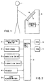
- FIG. 1 is a view schematically showing an automatic teller machine as a display control apparatus according to an embodiment of the present invention.
- an automatic teller machine 5 has a liquid crystal monitor (liquid crystal display means) 2 having a touch panel 4, and a control unit (field angle control means and control means) 3.
- a user interface (input reception means) for receiving input from a user is formed by combining the touch panel 4 and the liquid crystal monitor 2.
- the control unit (CPU) 3 performs various control for the automatic teller machine 5. Under the control of the control unit 3, the operation screen displayed on the liquid crystal monitor 2 is switched. The control unit 3 also controls the field angle of the liquid crystal monitor 2. Field angle control for the liquid crystal monitor 2 will be described later in detail.
- the liquid crystal monitor 2 comprises, e.g., an active matrix liquid crystal display panel using a thin-film transistor (TFT).
- TFT thin-film transistor
- the liquid crystal monitor 2 displays various operation screen under the control of the control unit 3.
- a user 1 inputs necessary information through the touch panel 4 while observing the operation screen displayed on the liquid crystal monitor 2.
- the information input through the touch panel 4 is sent to the control unit 3.
- the control unit 3 causes the liquid crystal monitor 2 to display a predetermined operation screen in accordance with the input information.
- FIG. 2 is a block diagram showing the schematic arrangement of the automatic teller machine.
- the automatic teller machine 5 has the control unit 3.
- This control unit 3 is connected to the liquid crystal monitor 2, the touch panel 4, a hard disk drive 6, a floppy disk drive 7, a printer 8, a card reader/writer 9, a ROM 10, and a RAM 11.
- the card reader/writer 9 reads out information recorded in various cards (e.g., an IC card or magnetic card) and writes predetermined information in the cards.
- a liquid crystal panel (corresponding to the liquid crystal monitor 2) and a CRT display panel will be briefly compared.
- the field angle of the liquid crystal display panel is smaller than that of the CRT display panel.
- the drive circuit of the liquid crystal display panel controls the display screen to obtain high contrast. More specifically, the drive circuit of the liquid crystal display panel performs control such that the difference in light emission luminance between the background portion and character portion of the display screen becomes large. That is, to increase the field angle, the difference in light emission luminance between the background portion and character portion of the display screen is increased. Under such control, the liquid crystal display panel obtains a maximum field angle. Conversely, when the difference in light emission luminance between the background portion and character portion of the display screen is controlled to be small, the field angle of the liquid crystal display panel becomes small.
- the basic design of the display screen is not changed even when the contents displayed on the display screen are switched.
- the field angle of this specific operation screen is made small under the above-described field angle control, thereby preventing a third party from looking at contents input through the specific operation screen.
- the specific operation screen where security must be ensured is a password input screen or an amount input screen.
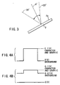
- the monitor 2 When the field angle of the operation screen displayed on the liquid crystal monitor 2 is not controlled to be small (when the operation screen is controlled to a normal field angle), the monitor 2 has a field angle shown in FIG. 3.
- the field angle of the liquid crystal monitor 2 controlled to the normal field angle is +20° to -30°.
- the direction perpendicular to a display surface 2a of the liquid crystal monitor 2 is defined as 0°.
- the contrast of the operation screen looked at from the direction (0°) perpendicular to the liquid crystal monitor 2 controlled to the normal field angle is assumed to be 1, the contrast of the operation screen viewed from the direction of the upper limit angle (+20°) or lower limit angle (-30°) is 1/10.
- the field angle of the operation screen displayed on the liquid crystal monitor 2 is controlled to be small (when the operation screen is controlled to a special field angle), the field angle of the monitor 2 is, e.g., 1/10 the normal field angle.
- the contrast of the operation screen looked at from the direction (0°) perpendicular to the liquid crystal monitor 2 controlled to the normal field angle is assumed to be 1
- the contrast of the operation screen viewed from the direction perpendicular to the liquid crystal monitor 2 controlled to the special field angle is 1/10.
- the liquid crystal monitor 2 controlled to the special field angle is looked at from the direction perpendicular to the monitor 2, the contents displayed on the operation screen can be sufficiently confirmed.
- the contrast of the operation screen looked at from the direction (0°) perpendicular to the liquid crystal monitor 2 controlled to the normal field angle is assumed to be 1
- the contrast of the operation screen when the liquid crystal monitor 2 controlled to the special field angle is viewed from the direction of the upper limit angle (+20°) or lower limit angle (-30°) is 1/100. That is, when the liquid crystal monitor 2 controlled to the special field angle is viewed from the direction of the upper limit angle (+20°) or lower limit angle (-30°), the contents displayed on the operation screen cannot be confirmed. More specifically, it is seemed as if nothing were displayed on the operation screen.
- video signals of signal levels as shown in FIG. 4A are input to the liquid crystal monitor 2.
- a video signal corresponding to the character and graphic portions of the operation screen is set at a signal level (amplitude) of 0.7 (V)
- a video signal corresponding to the background of the operation screen is set at a signal level (amplitude) of 0V.
- the luminance of the character and graphic portions of the operation screen of the monitor 2 is 200 (cd/m 2 ).
- the luminance of the background portion of the operation screen of the monitor 2 is 0 (cd/m 2 ).
- the difference in luminance between the character and graphic portions and the background portion of the operation screen of the liquid crystal monitor 2 is 200 (cd/m 2 ).
- video signals of the following signal levels are input to the liquid crystal monitor 2.
- the video signal corresponding to the character and graphic portions of the operation screen is set at a signal level (amplitude) of 0.7 (V), and the video signal corresponding to the background of the operation screen is set at a signal level (amplitude) of 0.67V.
- the luminance of the character and graphic portions of the operation screen of the monitor 2 is 200 (cd/m 2 ).
- the luminance of the background portion of the operation screen of the monitor 2 is 180 (cd/m 2 ). Therefore, when the liquid crystal monitor 2 is controlled to the special field angle, the difference in luminance between the character and graphic portions and the background portion of the operation screen of the monitor 2 is 20 (cd/m 2 ). This luminance difference is 1/10 that obtained by controlling the liquid crystal monitor 2 to the normal field angle.
- the contrast of the operation screen is controlled.
- the field angle of the liquid crystal monitor 2 is controlled.
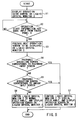
- FIG. 5 is a flow chart for explaining field angle control for the liquid crystal monitor of the automatic teller machine.
- step S1 under the control of the control unit 3, an operation guide screen is displayed on the liquid crystal monitor 2.
- a commercial screen may be displayed in place of the operation guide screen.
- step S2 it is determined whether operation start information has been input through the touch panel 4.
- Information input through the touch panel 4 is supplied to the control unit 3.
- the control unit 3 determines whether operation start information has been input through the touch panel 4. It is determined on the basis of the determination result in step S2 whether the automatic teller machine 5 is to be used. If it is determined in step S2 that the operation start information has been input through the touch panel 4 (YES in step S2), the next operation screen to be displayed on the liquid crystal monitor 2 is prepared (step S3). This preparation is made by the control unit 3.
- step S4 it is determined whether the operation screen prepared in step S3 is a password input screen. If the prepared operation screen corresponds to a password input screen (YES in step S4), the liquid crystal monitor 2 is controlled to the special field angle by the control unit 3 (step S7). More specifically, a video signal of 0.7 (V) corresponding to the character and graphic portions and a video signal of 0.67 (V) corresponding to the background are supplied to the liquid crystal monitor 2. Then, the operation screen is displayed on the liquid crystal monitor 2 in accordance with the video signal of 0.7 (V) corresponding to the character and graphic portions and the video signal of 0.67 (V) corresponding to the background.
- step S5 It is determined in step S5 whether the operation screen prepared in step S3 is an amount input screen. If the prepared operation screen corresponds to an amount input screen (YES in step S5), the liquid crystal monitor 2 is controlled to the special field angle by the control unit 3 (step S7). More specifically, a video signal of 0.7 (V) corresponding to the character and graphic portions and a video signal of 0.67 (V) corresponding to the background are supplied to the liquid crystal monitor 2. So, the operation screen is displayed on the liquid crystal monitor 2 in accordance with the video signal of 0.7 (V) corresponding to the character and graphic portions and the video signal of 0.67 (V) corresponding to the background.
- step S5 If it is determined that the prepared operation screen does not correspond to the amount input screen (NO in step S5), the liquid crystal monitor 2 is controlled to the normal field angle by the control unit 3 (step S6). More specifically, a video signal of 0.7 (V) corresponding to the character and graphic portions and a video signal of 0 (V) corresponding to the background are supplied to the liquid crystal monitor 2. Consequently, the operation screen is displayed on the liquid crystal monitor 2 in accordance with the video signal of 0.7 (V) corresponding to the character and graphic portions and the video signal of 0 (V) corresponding to the background.
- the liquid crystal monitor 2 when the operation screen to be displayed on the liquid crystal monitor 2 corresponds to a specific operation screen (password input screen or amount input screen), the liquid crystal monitor 2 is controlled to the special field angle.
- the operation screen to be displayed on the liquid crystal monitor 2 does not correspond to the specific operation screen (password input screen or amount input screen)
- the liquid crystal monitor 2 is controlled to the normal field angle.
- information such as the password input on the password input screen or amount input on the amount input screen can be prevented from leaking to a third party. That is, even when a third party who is awaiting use of the automatic teller machine behind the user who is using the automatic teller machine looks at the operation screen, he or she cannot make out the contents of operation screen.
- the present invention is also characterized in that the liquid crystal monitor is not always controlled to the special field angle. If the liquid crystal monitor is always controlled to the special field angle, the liquid crystal monitor of an automatic teller machine which is not being operated seems to display nothing. This may mislead users to make them think that the automatic teller machine has come to a stop or has malfunctions.
- the liquid crystal monitor when an operation screen which does not correspond to the specific operation screen is displayed, the liquid crystal monitor is controlled to the normal field angle. Owing to this, misguiding users that the automatic teller machine has come to a stop or has malfunctions can be avoided by displaying an operation guide screen or commercial screen on the liquid crystal monitor of the automatic teller machine which is not being operated.
Landscapes
- Engineering & Computer Science (AREA)
- Theoretical Computer Science (AREA)
- Physics & Mathematics (AREA)
- Crystallography & Structural Chemistry (AREA)
- Computer Hardware Design (AREA)
- General Physics & Mathematics (AREA)
- Chemical & Material Sciences (AREA)
- Liquid Crystal Display Device Control (AREA)
- Control Of Indicators Other Than Cathode Ray Tubes (AREA)
- Digital Computer Display Output (AREA)
- Controls And Circuits For Display Device (AREA)
- Liquid Crystal (AREA)
- User Interface Of Digital Computer (AREA)
Applications Claiming Priority (3)
| Application Number | Priority Date | Filing Date | Title |
|---|---|---|---|
| JP4616797 | 1997-02-28 | ||
| JP4616797A JPH10240186A (ja) | 1997-02-28 | 1997-02-28 | 表示制御装置および表示制御方法 |
| JP46167/97 | 1997-02-28 |
Publications (3)
| Publication Number | Publication Date |
|---|---|
| EP0862157A2 true EP0862157A2 (de) | 1998-09-02 |
| EP0862157A3 EP0862157A3 (de) | 1999-05-06 |
| EP0862157B1 EP0862157B1 (de) | 2001-05-09 |
Family
ID=12739471
Family Applications (1)
| Application Number | Title | Priority Date | Filing Date |
|---|---|---|---|
| EP98103147A Expired - Lifetime EP0862157B1 (de) | 1997-02-28 | 1998-02-23 | Verfahren und Einrichtung zur Steuerung einer Anzeige |
Country Status (6)
| Country | Link |
|---|---|
| US (1) | US6205554B1 (de) |
| EP (1) | EP0862157B1 (de) |
| JP (1) | JPH10240186A (de) |
| CN (1) | CN1192019A (de) |
| DE (1) | DE69800765T2 (de) |
| TW (1) | TW379312B (de) |
Cited By (1)
| Publication number | Priority date | Publication date | Assignee | Title |
|---|---|---|---|---|
| EP2387028A1 (de) * | 2010-05-14 | 2011-11-16 | Sony Ericsson Mobile Communications AB | Anzeigeanordnung und Verfahren zur Anzeige von Inhalt |
Families Citing this family (20)
| Publication number | Priority date | Publication date | Assignee | Title |
|---|---|---|---|---|
| GB9808024D0 (en) * | 1998-04-17 | 1998-06-17 | Ncr Int Inc | Data processing apparatus including an output display |
| JPWO2006025340A1 (ja) * | 2004-08-30 | 2008-05-08 | シャープ株式会社 | 表示制御デバイス、表示装置、表示デバイスの制御方法、表示制御プログラム、および該プログラムを記録した記録媒体 |
| US8094103B2 (en) | 2004-08-31 | 2012-01-10 | Sharp Kabushiki Kaisha | Viewing-angle control device, display apparatus, method for controlling viewing-angle control device, viewing-angle control program, and storage medium storing the program |
| WO2006027995A1 (ja) | 2004-09-07 | 2006-03-16 | Sharp Kabushiki Kaisha | 表示装置、視野角制御装置、および電子機器 |
| US7817106B2 (en) | 2004-09-15 | 2010-10-19 | Sharp Kabushiki Kaisha | Display device, viewing angle control device, and electronic apparatus |
| WO2006030745A1 (ja) | 2004-09-17 | 2006-03-23 | Sharp Kabushiki Kaisha | 表示装置および視野角制御装置、電子機器 |
| WO2006038574A1 (ja) | 2004-10-04 | 2006-04-13 | Sharp Kabushiki Kaisha | 表示装置および電子機器 |
| JP4297068B2 (ja) * | 2005-03-17 | 2009-07-15 | 沖電気工業株式会社 | 顧客操作型端末装置 |
| JP2007083425A (ja) * | 2005-09-20 | 2007-04-05 | Sharp Corp | 画像処理装置 |
| JP2007188153A (ja) * | 2006-01-11 | 2007-07-26 | Oki Electric Ind Co Ltd | 自動取引装置 |
| KR101019483B1 (ko) * | 2006-10-23 | 2011-03-07 | 엘지전자 주식회사 | 모니터 및 이를 이용한 시야각 조절 방법 |
| JP2008176148A (ja) * | 2007-01-19 | 2008-07-31 | Nintendo Co Ltd | 液晶表示制御装置および液晶表示制御プログラム |
| TWI489870B (zh) * | 2007-12-31 | 2015-06-21 | Htc Corp | 動態調整螢幕視角的方法及裝置 |
| US8549314B2 (en) | 2010-04-29 | 2013-10-01 | King Saud University | Password generation methods and systems |
| CN102169610A (zh) * | 2010-12-24 | 2011-08-31 | 广州广电运通金融电子股份有限公司 | 交易信息的保密显示方法及其显示系统 |
| JP2012174208A (ja) | 2011-02-24 | 2012-09-10 | Sony Corp | 情報処理装置、情報処理方法、プログラム及び端末装置 |
| WO2013107018A1 (en) * | 2012-01-19 | 2013-07-25 | Microsoft Corporation | Simultaneous display of multiple content items |
| KR101991133B1 (ko) | 2012-11-20 | 2019-06-19 | 마이크로소프트 테크놀로지 라이센싱, 엘엘씨 | 헤드 마운트 디스플레이 및 그 제어 방법 |
| KR102471174B1 (ko) * | 2015-10-06 | 2022-11-28 | 삼성전자주식회사 | 테마 적용 방법 및 이를 수행하는 전자 장치 |
| CN108763974A (zh) * | 2018-06-25 | 2018-11-06 | 重庆邮电大学 | 基于频域图像混合的移动终端触摸屏密码键盘防窥视方法 |
Family Cites Families (9)
| Publication number | Priority date | Publication date | Assignee | Title |
|---|---|---|---|---|
| JPH047627A (ja) * | 1990-04-25 | 1992-01-13 | Shimadzu Corp | 液晶表示タブレット |
| US5489918A (en) * | 1991-06-14 | 1996-02-06 | Rockwell International Corporation | Method and apparatus for dynamically and adjustably generating active matrix liquid crystal display gray level voltages |
| JPH06296153A (ja) | 1992-01-10 | 1994-10-21 | Oi Denki Kk | 表示器付き選択呼出携帯用受信機 |
| FR2693815A1 (fr) * | 1992-07-15 | 1994-01-21 | Gemplus Card Int | Procédé de protection d'un clavier de saisie de données, et clavier pour mise en Óoeuvre. |
| US5835074A (en) * | 1992-12-30 | 1998-11-10 | Advanced Displays Corporation | Method to change the viewing angle in a fixed liquid crystal display by changing the pre-tilt angle in the liquid crystal layer with a bias voltage |
| JP3102970B2 (ja) * | 1993-07-28 | 2000-10-23 | シャープ株式会社 | 情報表示装置およびその製造方法 |
| US5644415A (en) * | 1993-12-20 | 1997-07-01 | Casio Computer Co., Ltd. | Liquid crystal display device having wide field angle |
| CN1146252A (zh) * | 1994-04-07 | 1997-03-26 | 波音公司 | 图像显示系统 |
| JP3115509B2 (ja) * | 1995-06-22 | 2000-12-11 | シャープ株式会社 | 液晶表示装置 |
-
1997
- 1997-02-28 JP JP4616797A patent/JPH10240186A/ja active Pending
-
1998
- 1998-02-07 TW TW087101647A patent/TW379312B/zh not_active IP Right Cessation
- 1998-02-23 EP EP98103147A patent/EP0862157B1/de not_active Expired - Lifetime
- 1998-02-23 DE DE69800765T patent/DE69800765T2/de not_active Expired - Lifetime
- 1998-02-27 CN CN98105283A patent/CN1192019A/zh active Pending
- 1998-02-27 US US09/032,022 patent/US6205554B1/en not_active Expired - Fee Related
Cited By (1)
| Publication number | Priority date | Publication date | Assignee | Title |
|---|---|---|---|---|
| EP2387028A1 (de) * | 2010-05-14 | 2011-11-16 | Sony Ericsson Mobile Communications AB | Anzeigeanordnung und Verfahren zur Anzeige von Inhalt |
Also Published As
| Publication number | Publication date |
|---|---|
| TW379312B (en) | 2000-01-11 |
| DE69800765D1 (de) | 2001-06-13 |
| EP0862157B1 (de) | 2001-05-09 |
| EP0862157A3 (de) | 1999-05-06 |
| CN1192019A (zh) | 1998-09-02 |
| JPH10240186A (ja) | 1998-09-11 |
| US6205554B1 (en) | 2001-03-20 |
| DE69800765T2 (de) | 2001-09-27 |
Similar Documents
| Publication | Publication Date | Title |
|---|---|---|
| EP0862157B1 (de) | Verfahren und Einrichtung zur Steuerung einer Anzeige | |
| US5835603A (en) | Financial transaction system | |
| EP0732647B1 (de) | Videoanzeige und -steuerung von mehreren grafischen Schnittstellen | |
| WO2016070177A1 (en) | Automated banking machine | |
| EP0370055B1 (de) | Wechselwirkendes pumpsystem | |
| US20170091731A1 (en) | Automated banking machine | |
| WO2002039656A1 (en) | Method and apparatus for inputting secret information | |
| KR20090067696A (ko) | 핀패드를 이용한 광고방법 | |
| JP5100404B2 (ja) | 取引処理装置 | |
| JP2005004488A (ja) | 自動取引装置 | |
| US5974143A (en) | Virus-resistent mechanism for transaction verification to confirming user | |
| US8872834B2 (en) | Electronic payment terminal with an improved display | |
| US8359546B2 (en) | System, method and computer-readable medium for online marketing and visual presentations of software programs | |
| JP3888708B2 (ja) | 自動取引装置の取引選択方法及びその自動取引装置 | |
| KR20010104838A (ko) | 금융 자동화기기의 동영상 구동장치 | |
| JPH0644283A (ja) | 顧客操作誘導方式 | |
| KR100553084B1 (ko) | 금융자동화기기의 광고 화면 제어 방법 | |
| JP2002024903A (ja) | 現金自動取引装置 | |
| JP3482587B2 (ja) | 自動取引装置及び自動振込システム | |
| CN101238495A (zh) | 验证用户的交易权限的交易系统、方法和自动柜员机 | |
| KR101000240B1 (ko) | 보조계원조작부를 구비하는 금융자동화기기 | |
| JP2025096058A (ja) | 自動取引装置、自動取引方法及び自動取引プログラム | |
| JPH10275266A (ja) | 情報端末装置 | |
| JPH10240844A (ja) | 自動取引装置を用いた情報提供システム | |
| JPH11213049A (ja) | 自動カード発行機 |
Legal Events
| Date | Code | Title | Description |
|---|---|---|---|
| PUAI | Public reference made under article 153(3) epc to a published international application that has entered the european phase |
Free format text: ORIGINAL CODE: 0009012 |
|
| 17P | Request for examination filed |
Effective date: 19980223 |
|
| AK | Designated contracting states |
Kind code of ref document: A2 Designated state(s): DE FR GB NL |
|
| AX | Request for extension of the european patent |
Free format text: AL;LT;LV;MK;RO;SI |
|
| PUAL | Search report despatched |
Free format text: ORIGINAL CODE: 0009013 |
|
| AK | Designated contracting states |
Kind code of ref document: A3 Designated state(s): AT BE CH DE DK ES FI FR GB GR IE IT LI LU MC NL PT SE |
|
| AX | Request for extension of the european patent |
Free format text: AL;LT;LV;MK;RO;SI |
|
| AKX | Designation fees paid |
Free format text: DE FR GB NL |
|
| GRAG | Despatch of communication of intention to grant |
Free format text: ORIGINAL CODE: EPIDOS AGRA |
|
| 17Q | First examination report despatched |
Effective date: 20000629 |
|
| GRAG | Despatch of communication of intention to grant |
Free format text: ORIGINAL CODE: EPIDOS AGRA |
|
| GRAH | Despatch of communication of intention to grant a patent |
Free format text: ORIGINAL CODE: EPIDOS IGRA |
|
| GRAH | Despatch of communication of intention to grant a patent |
Free format text: ORIGINAL CODE: EPIDOS IGRA |
|
| GRAA | (expected) grant |
Free format text: ORIGINAL CODE: 0009210 |
|
| AK | Designated contracting states |
Kind code of ref document: B1 Designated state(s): DE FR GB NL |
|
| REF | Corresponds to: |
Ref document number: 69800765 Country of ref document: DE Date of ref document: 20010613 |
|
| ET | Fr: translation filed | ||
| REG | Reference to a national code |
Ref country code: GB Ref legal event code: IF02 |
|
| PLBE | No opposition filed within time limit |
Free format text: ORIGINAL CODE: 0009261 |
|
| STAA | Information on the status of an ep patent application or granted ep patent |
Free format text: STATUS: NO OPPOSITION FILED WITHIN TIME LIMIT |
|
| 26N | No opposition filed | ||
| PGFP | Annual fee paid to national office [announced via postgrant information from national office to epo] |
Ref country code: NL Payment date: 20070204 Year of fee payment: 10 |
|
| NLV4 | Nl: lapsed or anulled due to non-payment of the annual fee |
Effective date: 20080901 |
|
| PG25 | Lapsed in a contracting state [announced via postgrant information from national office to epo] |
Ref country code: NL Free format text: LAPSE BECAUSE OF NON-PAYMENT OF DUE FEES Effective date: 20080901 |
|
| PGFP | Annual fee paid to national office [announced via postgrant information from national office to epo] |
Ref country code: FR Payment date: 20100223 Year of fee payment: 13 |
|
| PGFP | Annual fee paid to national office [announced via postgrant information from national office to epo] |
Ref country code: GB Payment date: 20100202 Year of fee payment: 13 Ref country code: DE Payment date: 20100303 Year of fee payment: 13 |
|
| GBPC | Gb: european patent ceased through non-payment of renewal fee |
Effective date: 20110223 |
|
| REG | Reference to a national code |
Ref country code: FR Ref legal event code: ST Effective date: 20111102 |
|
| PG25 | Lapsed in a contracting state [announced via postgrant information from national office to epo] |
Ref country code: FR Free format text: LAPSE BECAUSE OF NON-PAYMENT OF DUE FEES Effective date: 20110228 |
|
| REG | Reference to a national code |
Ref country code: DE Ref legal event code: R119 Ref document number: 69800765 Country of ref document: DE Effective date: 20110901 |
|
| PG25 | Lapsed in a contracting state [announced via postgrant information from national office to epo] |
Ref country code: GB Free format text: LAPSE BECAUSE OF NON-PAYMENT OF DUE FEES Effective date: 20110223 |
|
| PG25 | Lapsed in a contracting state [announced via postgrant information from national office to epo] |
Ref country code: DE Free format text: LAPSE BECAUSE OF NON-PAYMENT OF DUE FEES Effective date: 20110901 |