EP0860562A2 - Verlegesystem und Spanneinrichtung für ein Verlegesystem sowie Verlegeverfahren - Google Patents
Verlegesystem und Spanneinrichtung für ein Verlegesystem sowie Verlegeverfahren Download PDFInfo
- Publication number
- EP0860562A2 EP0860562A2 EP98103044A EP98103044A EP0860562A2 EP 0860562 A2 EP0860562 A2 EP 0860562A2 EP 98103044 A EP98103044 A EP 98103044A EP 98103044 A EP98103044 A EP 98103044A EP 0860562 A2 EP0860562 A2 EP 0860562A2
- Authority
- EP
- European Patent Office
- Prior art keywords
- plate elements
- recesses
- devices
- alignment devices
- laying
- Prior art date
- Legal status (The legal status is an assumption and is not a legal conclusion. Google has not performed a legal analysis and makes no representation as to the accuracy of the status listed.)
- Granted
Links
- 238000000034 method Methods 0.000 title claims description 11
- 239000000463 material Substances 0.000 claims abstract description 26
- 239000002023 wood Substances 0.000 claims abstract description 21
- 230000002093 peripheral effect Effects 0.000 claims description 32
- 239000007799 cork Substances 0.000 claims description 21
- 229920001971 elastomer Polymers 0.000 claims description 19
- 239000002184 metal Substances 0.000 claims description 19
- 239000005060 rubber Substances 0.000 claims description 19
- 239000000835 fiber Substances 0.000 claims description 16
- 244000060011 Cocos nucifera Species 0.000 claims description 15
- 235000013162 Cocos nucifera Nutrition 0.000 claims description 15
- 229920001821 foam rubber Polymers 0.000 claims description 8
- 230000008878 coupling Effects 0.000 claims description 7
- 238000010168 coupling process Methods 0.000 claims description 7
- 238000005859 coupling reaction Methods 0.000 claims description 7
- 238000013461 design Methods 0.000 claims description 7
- 244000198134 Agave sisalana Species 0.000 claims description 4
- 244000025254 Cannabis sativa Species 0.000 claims description 4
- 235000012766 Cannabis sativa ssp. sativa var. sativa Nutrition 0.000 claims description 4
- 235000012765 Cannabis sativa ssp. sativa var. spontanea Nutrition 0.000 claims description 4
- 240000000491 Corchorus aestuans Species 0.000 claims description 4
- 235000011777 Corchorus aestuans Nutrition 0.000 claims description 4
- 235000010862 Corchorus capsularis Nutrition 0.000 claims description 4
- 235000009120 camo Nutrition 0.000 claims description 4
- 235000005607 chanvre indien Nutrition 0.000 claims description 4
- 239000011487 hemp Substances 0.000 claims description 4
- 238000003780 insertion Methods 0.000 claims description 4
- 230000037431 insertion Effects 0.000 claims description 4
- 239000004033 plastic Substances 0.000 claims description 4
- 229920003023 plastic Polymers 0.000 claims description 4
- 210000002268 wool Anatomy 0.000 claims description 4
- 239000002131 composite material Substances 0.000 claims description 3
- 230000008602 contraction Effects 0.000 claims description 3
- 239000004575 stone Substances 0.000 claims description 3
- 239000002648 laminated material Substances 0.000 claims description 2
- 239000000314 lubricant Substances 0.000 claims description 2
- 230000036316 preload Effects 0.000 claims description 2
- 239000000344 soap Substances 0.000 claims description 2
- 238000009408 flooring Methods 0.000 abstract description 7
- 230000036961 partial effect Effects 0.000 description 18
- 238000009434 installation Methods 0.000 description 15
- 230000008901 benefit Effects 0.000 description 12
- 210000000078 claw Anatomy 0.000 description 7
- 230000015572 biosynthetic process Effects 0.000 description 5
- 230000000694 effects Effects 0.000 description 5
- 238000005755 formation reaction Methods 0.000 description 5
- 238000011161 development Methods 0.000 description 4
- 230000018109 developmental process Effects 0.000 description 4
- 230000008569 process Effects 0.000 description 4
- 239000000758 substrate Substances 0.000 description 4
- 239000013013 elastic material Substances 0.000 description 3
- 238000009413 insulation Methods 0.000 description 3
- 238000004519 manufacturing process Methods 0.000 description 3
- 230000002829 reductive effect Effects 0.000 description 3
- 125000006850 spacer group Chemical group 0.000 description 3
- RNFJDJUURJAICM-UHFFFAOYSA-N 2,2,4,4,6,6-hexaphenoxy-1,3,5-triaza-2$l^{5},4$l^{5},6$l^{5}-triphosphacyclohexa-1,3,5-triene Chemical compound N=1P(OC=2C=CC=CC=2)(OC=2C=CC=CC=2)=NP(OC=2C=CC=CC=2)(OC=2C=CC=CC=2)=NP=1(OC=1C=CC=CC=1)OC1=CC=CC=C1 RNFJDJUURJAICM-UHFFFAOYSA-N 0.000 description 2
- RRHGJUQNOFWUDK-UHFFFAOYSA-N Isoprene Chemical compound CC(=C)C=C RRHGJUQNOFWUDK-UHFFFAOYSA-N 0.000 description 2
- 239000003063 flame retardant Substances 0.000 description 2
- 230000007246 mechanism Effects 0.000 description 2
- 229930014626 natural product Natural products 0.000 description 2
- 229920001195 polyisoprene Polymers 0.000 description 2
- 238000009423 ventilation Methods 0.000 description 2
- 235000009854 Cucurbita moschata Nutrition 0.000 description 1
- 240000001980 Cucurbita pepo Species 0.000 description 1
- 235000009852 Cucurbita pepo Nutrition 0.000 description 1
- 206010017577 Gait disturbance Diseases 0.000 description 1
- 241000110717 Sclerolaena bicornis Species 0.000 description 1
- 229910000831 Steel Inorganic materials 0.000 description 1
- 230000009471 action Effects 0.000 description 1
- 239000000853 adhesive Substances 0.000 description 1
- 230000001070 adhesive effect Effects 0.000 description 1
- 230000004888 barrier function Effects 0.000 description 1
- 230000000052 comparative effect Effects 0.000 description 1
- 230000001419 dependent effect Effects 0.000 description 1
- 238000010586 diagram Methods 0.000 description 1
- 238000009826 distribution Methods 0.000 description 1
- 238000005562 fading Methods 0.000 description 1
- 210000003746 feather Anatomy 0.000 description 1
- 239000004746 geotextile Substances 0.000 description 1
- 239000003292 glue Substances 0.000 description 1
- 238000000227 grinding Methods 0.000 description 1
- 230000006872 improvement Effects 0.000 description 1
- 230000000670 limiting effect Effects 0.000 description 1
- 238000003801 milling Methods 0.000 description 1
- 238000012986 modification Methods 0.000 description 1
- 230000004048 modification Effects 0.000 description 1
- 235000019645 odor Nutrition 0.000 description 1
- 230000001151 other effect Effects 0.000 description 1
- 239000002245 particle Substances 0.000 description 1
- 238000003825 pressing Methods 0.000 description 1
- 230000001681 protective effect Effects 0.000 description 1
- 230000001105 regulatory effect Effects 0.000 description 1
- 230000008439 repair process Effects 0.000 description 1
- 239000012858 resilient material Substances 0.000 description 1
- 230000000717 retained effect Effects 0.000 description 1
- 230000002441 reversible effect Effects 0.000 description 1
- 238000010079 rubber tapping Methods 0.000 description 1
- 239000007787 solid Substances 0.000 description 1
- 239000011343 solid material Substances 0.000 description 1
- 239000002904 solvent Substances 0.000 description 1
- 235000020354 squash Nutrition 0.000 description 1
- 239000010959 steel Substances 0.000 description 1
- 238000003860 storage Methods 0.000 description 1
- 238000005728 strengthening Methods 0.000 description 1
- 238000006467 substitution reaction Methods 0.000 description 1
- 239000000725 suspension Substances 0.000 description 1
- 230000008961 swelling Effects 0.000 description 1
- 238000004804 winding Methods 0.000 description 1
Images


Classifications
-
- E—FIXED CONSTRUCTIONS
- E04—BUILDING
- E04F—FINISHING WORK ON BUILDINGS, e.g. STAIRS, FLOORS
- E04F15/00—Flooring
- E04F15/22—Resiliently-mounted floors, e.g. sprung floors
-
- E—FIXED CONSTRUCTIONS
- E04—BUILDING
- E04F—FINISHING WORK ON BUILDINGS, e.g. STAIRS, FLOORS
- E04F15/00—Flooring
- E04F15/02—Flooring or floor layers composed of a number of similar elements
- E04F15/02005—Construction of joints, e.g. dividing strips
- E04F15/02027—Means for spacing the flooring from an adjoining wall
-
- E—FIXED CONSTRUCTIONS
- E04—BUILDING
- E04F—FINISHING WORK ON BUILDINGS, e.g. STAIRS, FLOORS
- E04F15/00—Flooring
- E04F15/02—Flooring or floor layers composed of a number of similar elements
- E04F15/04—Flooring or floor layers composed of a number of similar elements only of wood or with a top layer of wood, e.g. with wooden or metal connecting members
- E04F15/048—Flooring or floor layers composed of a number of similar elements only of wood or with a top layer of wood, e.g. with wooden or metal connecting members with a top surface of assembled elongated wooden strip type
-
- E—FIXED CONSTRUCTIONS
- E04—BUILDING
- E04F—FINISHING WORK ON BUILDINGS, e.g. STAIRS, FLOORS
- E04F21/00—Implements for finishing work on buildings
- E04F21/20—Implements for finishing work on buildings for laying flooring
- E04F21/22—Implements for finishing work on buildings for laying flooring of single elements, e.g. flooring cramps ; flexible webs
-
- E—FIXED CONSTRUCTIONS
- E04—BUILDING
- E04F—FINISHING WORK ON BUILDINGS, e.g. STAIRS, FLOORS
- E04F19/00—Other details of constructional parts for finishing work on buildings
- E04F19/02—Borders; Finishing strips, e.g. beadings; Light coves
- E04F19/04—Borders; Finishing strips, e.g. beadings; Light coves for use between floor or ceiling and wall, e.g. skirtings
-
- E—FIXED CONSTRUCTIONS
- E04—BUILDING
- E04F—FINISHING WORK ON BUILDINGS, e.g. STAIRS, FLOORS
- E04F15/00—Flooring
- E04F15/02—Flooring or floor layers composed of a number of similar elements
- E04F15/02044—Separate elements for fastening to an underlayer
- E04F2015/0205—Separate elements for fastening to an underlayer with load-supporting elongated furring elements between the flooring elements and the underlayer
-
- E—FIXED CONSTRUCTIONS
- E04—BUILDING
- E04F—FINISHING WORK ON BUILDINGS, e.g. STAIRS, FLOORS
- E04F19/00—Other details of constructional parts for finishing work on buildings
- E04F19/02—Borders; Finishing strips, e.g. beadings; Light coves
- E04F19/04—Borders; Finishing strips, e.g. beadings; Light coves for use between floor or ceiling and wall, e.g. skirtings
- E04F2019/0404—Borders; Finishing strips, e.g. beadings; Light coves for use between floor or ceiling and wall, e.g. skirtings characterised by the material
- E04F2019/0422—Borders; Finishing strips, e.g. beadings; Light coves for use between floor or ceiling and wall, e.g. skirtings characterised by the material of organic plastics with or without reinforcements or filling materials
-
- E—FIXED CONSTRUCTIONS
- E04—BUILDING
- E04F—FINISHING WORK ON BUILDINGS, e.g. STAIRS, FLOORS
- E04F2201/00—Joining sheets or plates or panels
- E04F2201/02—Non-undercut connections, e.g. tongue and groove connections
- E04F2201/025—Non-undercut connections, e.g. tongue and groove connections with tongue and grooves alternating transversally in the direction of the thickness of the panel, e.g. multiple tongue and grooves oriented parallel to each other
-
- E—FIXED CONSTRUCTIONS
- E04—BUILDING
- E04F—FINISHING WORK ON BUILDINGS, e.g. STAIRS, FLOORS
- E04F2201/00—Joining sheets or plates or panels
- E04F2201/04—Other details of tongues or grooves
- E04F2201/042—Other details of tongues or grooves with grooves positioned on the rear-side of the panel
Definitions
- the invention relates to a laying system and a laying method with plate elements according to the preambles of the claim 1 or claim 9. Furthermore, the invention is concerned with tensioning devices according to the preamble of the claim 8th.
- Such laying systems and laying methods are used to manufacture of floor coverings, such as parquet floors in particular.
- the latter consists of individual plate elements in Form of parquet flooring, planks or bars, on one Be laid underground and connected to each other.
- the plate elements are on are glued or nailed to the surface in the meantime in practice loose or so-called floating Parquet floors became known.
- a floating laying of a parquet floor has opposite a firm attachment of the plate elements to the substrate several advantages. The most important thing is that a floating parquet floor easily dismantled and can be relocated elsewhere without that individual plate elements are damaged or destroyed will. In the case of a floating installation, it is also advantageous that repairs on the parquet floor by replacing individual Plate elements made particularly simple and inexpensive can be. Compared to the glue, the floating laying of a parquet floor also the advantage that no harmful solvent vapors and unpleasant Odors arise that often do not last for a very long time completely disappear. Parquet floors nailed to the ground have the floating installation Disadvantages that this type of attachment is very material and time consuming and is negative when sanding the parquet floor affects.
- DE-PS 800 915 also shows a parquet board, which consists of individual parquet strips, which are aligned with each other Contain grooves in which ridges are inserted and are attached.
- This parquet board cannot be disassembled will. In addition, it cannot be adapted to any room size will.
- the aim of the present invention is a laying system and to create a laying process to easily slab elements, to be able to lay and dismantle safely and precisely.
- one top and one Have underside and intermediate circumferential sides, in which recesses for receiving alignment devices for the positive connection of at least two adjacent panel elements to be installed in the direction perpendicular and in are included in a direction parallel to the top, that the recesses and the alignment devices dimensioned so are that the latter is loosely slidable into the recesses fit, and that tensioning devices are provided, by means of those connected to one another via the alignment devices Plate elements can be acted upon one another.
- the alignment devices only form an adjustment and Attachment aid when laying the panel elements and must in any case no fixed fixation of the panel elements during installation accomplish each other. Take care of that at the latest after completion of a corresponding floor covering the tensioning devices. In any case, no force has to be applied the alignment devices into the recesses introduce. Furthermore, there is no special skill required for the smooth insertion of the alignment devices to make in the recesses. Thus in simple misalignment of the plate elements to each other excluded and the laying effort significantly reduced.
- the clamping devices reliably ensure sufficient Cohesion of the installed panel elements. Neither that Shrinkage / expansion behavior of some materials, still sliding loads when used, the connections separate the plate elements.
- the tensioning devices can either from plate element to plate element that is not immediate must be adjacent, directly when laying or preferably after laying partial areas or especially preferably used after laying the entire area.
- the Laying system provided that the alignment devices dowels and / or contain lasts between two or continuous over at least two plate elements to be laid adjacent can be used in their recesses.
- Last are particularly preferred, the length of which is more than two, for example five to seven, plate elements enough.
- Parquet floors are e.g. the problem that fluctuations the ambient temperature and humidity to expand and contract the plate elements.
- stretching the material can generally be two plate elements from the installation area to make room for the To create expansion of the entire parquet floor.
- the plate elements that are erected would be damaged, especially when the individual plate elements through Tongue and groove connections are connected because then the female connectors abort.
- This problem does not only exist with plate elements made of wood, but also with other materials, partly in more or less drastic effects and due to other effects, e.g. Sliding loads on the installed panel elements.
- Especially the version with Alignment devices in the form of strips with a length over more than two plate elements are sure to remedy this.
- the Setting up individual plate elements is effectively prevented and there may at most be a slight curvature of the entire Floor area come.
- the invention contain dowels and / or strips with a profile, such as. a round profile, a triangular profile or one Dovetail profile.
- a profile such as. a round profile, a triangular profile or one Dovetail profile.
- the recesses in the plate elements it is further preferred if the recesses in the plate elements to the profile of the dowels and / or Last have a suitable profile.
- strips are used as alignment devices, it is preferred if these have lengths that are greater than the dimensions of two plate elements through which they pass run, as already explained above. In particular, can it should also be provided that the strips are different Have lengths. As a result, not all strips end, e.g. Ridges, on a line on which it depends on the Material of the plate elements come to a weak point could, but the ends of the strips and thus the joints to subsequent strips are spread over an area.
- the dowels and / or ledges tapered ends for insertion have in the recesses. This is the threading the dowels and / or strips in the recesses or plugging the recesses on the dowels and / or strips facilitated.
- Laying system contains plate elements that are attached to their in Alignment devices used parallel to the recesses Circumferential sides have positive locking devices, the one Positive locking in the direction perpendicular to that in the recesses used alignment devices with an adjacent Result in plate element, e.g. Dovetail or hook designs on a plate element and corresponding groove on adjacent plate element.
- This can create further cohesion of the plate elements also in the direction perpendicular to the Alignment devices used in the recesses and Top of the plate elements can be reached.
- Particularly advantageous is this connection to plate elements on the edge of the Laying area, if not more space for entire panel elements is, so that any alignment devices may no longer be arranged can be. In such a case they are partial Panel elements not completely loosely inserted at the edge and would have to use nails or similar be fixed but are over the positive locking devices with the perpendicular to each aligning devices used in the recesses adjacent Plate elements connected.
- the recesses in the peripheral sides of the plate elements like a hole with a round or square profile and in particular closer to them Undersides lie.
- the one in the lower half the thickness of the plate elements lying down or groove-like recesses offer especially when later Parquet floors to be sanded down to about the To be able to grind half of their thickness without the connection the plate elements through the alignment devices is affected.
- the alignment devices are dimensioned in this way are that they are completely within the groove-like recesses lie and in particular with the underside of the plate elements form a flat surface. This makes the contact surface the plate elements with alignment devices on the surface optimal.
- the alignment devices can be so be dimensioned so that when they are plugged together with the recesses are over the bottom of the plate elements protrude from the groove-like recesses.
- the plate elements are then only on the alignment devices and it is a cavity between the pad and the plate elements educated. Such a cavity can on ceilings Walls or floors, for example for routing cabling be desirable. Can continue this way e.g. Adjust the unevenness of the base accordingly of the alignment devices are balanced.
- the plate elements In the case of alignment devices protruding from groove-like recesses can depend on the elastic properties the plate elements also have a spring action, for example the can be achieved with the latter occupied floor by the plate elements in their areas between the alignment devices can yield resiliently under load. This can e.g. by strengthening or optimizing that elastic means are provided, via which the alignment devices can be placed on a laying surface, such as a mat.
- elastic means such as elastic Material or individual springs
- this configuration can e.g. Swinging floors, but also in the event of an impact muffled wall coverings are produced.
- the installation system can also e.g. on a Beam underlay can be used.
- the distance of the groove-like Recesses should then correspond to the distance between the bars and the alignment devices could then simply be on the beams be attached.
- the cohesion and the alignment of the plate elements can are promoted in that the peripheral sides of the plate elements are profiled, in such a way that the peripheral side profiles match adjacent plate elements.
- Suitable Shapes are zigzag, wave, crown formations etc. These shapes preferably extend over the entire height of the peripheral sides of the plate elements, since then, for example, after repeated grinding of Panel elements made of wood.
- a preferred further development of the configuration specified above provides that the profiling of the peripheral pages of the plate elements in addition to the alignment devices Forms coupling devices, such as Tongue and groove connections, via which adjacent plate elements can be connected.
- Such coupling devices are basically for cohesion installed plate elements not necessary, but only contribute to the stability of the connection.
- the Coupling devices should also not be firmly connected be, but easily e.g. can be pushed into one another.
- a base for laying the plate elements is included.
- a base preferably has a mat-like or preferably mesh-like layer of or with preferably cork, rubber, caoutchouc, jute, sisal, hemp, Wool felt, coconut fibers, preferably a braided coconut fiber and particularly preferably a rubber pressed or siliconized coconut fiber braid.
- the document can be in Case of the version described above with on the bottom of the plate elements protruding alignment devices only be provided between the latter, i.e. in the formed Gaps between the surface and the panel elements as well as neighboring parallel alignment devices. In the latter Fall can also, as in the case that the alignment devices not from the undersides of the plate elements protrude downwards, the underlay over the entire installation area be provided.
- any network form with Natural fibers, a rubber net, a coconut roll mat, a net with integrated braid, an air chamber or tube network, a full-surface thin air mattress, depending on the desired Vibration behavior of the floor can be inflated can, etc. used to exemplify just a few ways to call.
- the tensioning devices from the outside at least two connected to each other via the alignment devices
- Pressure elements acting on their peripheral sides such as wood springs, metal springs, cork parts, Foam rubber parts and the like
- the clamping devices can also be between two neighboring ones connected via the alignment devices and / or not immediately adjacent plate elements include usable tension elements, such as Brackets, Tension straps and the like, which preferably over and / or to the Bottom of the plate elements are performed.
- usable tension elements such as Brackets, Tension straps and the like
- For internal bracing of partial areas can also be a bracing of several sub-areas with each other be provided.
- Particularly suitable for one Partial surface tensioning straps or belts these can either attack only in edge areas of the partial areas, or but on the undersides of individual plate elements of the partial areas attack using claws, hooks, clamps, etc. Should only cover a small area with plate elements individual ones between two neighboring ones are also suitable Plate elements used by means of which the two plate elements connected thereby pulled towards each other will.
- two-part edge strips can be provided, one Base bar for attachment to panel elements, an outer bar for attachment to an edge of the installation surface and compensation devices included, at least on the outer bar or are attached to the base bar and by means of which when moving the panel elements with the base strips gap occurring between the latter and the outer strips can be covered and / or locked.
- the compensation devices can be simple bands be made of elastic or non-elastic material. Elastic Bands are similar due to reversible stretching or Shrinkage according to the gap to be covered. in the In the case of non-elastic tapes, these must be made accordingly be dimensioned and placed according to the maximum expected column e.g. if the column is reduced, for example by expanding the wood material of the plate elements in folds together.
- Preferred materials for the panel elements are: wood, cork, Stone, plastic, composite material, laminate material, rubber, Metal. The same materials can be used for the alignment devices be used.
- the plate elements can preferably have an elongated shape have and in particular rod, slat or plank-like be.
- the recesses then run in particular transversely for the longitudinal expansion of the plate elements.
- positive locking devices it is preferred that, on the shorter circumferential end faces, positive locking devices, such as. one dovetail feather each and a dovetail groove are provided through which two adjacent plate elements fit and preferably firmly are interconnectable.
- Laying system can thereby according to further embodiments be taken care of that if the recesses do not have the entire plate element run through, on two opposite circumferential sides of the plate elements Recesses are preferably not aligned are. In the other case, if the recesses over the The recesses are the entire plate element preferred with respect to a center line parallel to them of the plate element are arranged asymmetrically or vertically in adjacent panel elements are at different points along their direction.
- each in a parallel to it Recessing circumferential side of the plate element is only half a recess, so alignment devices also run simultaneously in two plate elements, which thereby be aligned together.
- This is useful if for example parts of plate elements depending on remaining dimensions of the area to be covered are too small are to accommodate complete recesses.
- Such parts of Panel elements benefit in terms of their alignment and possibly also their connection to neighboring plate elements alignment devices common to the latter.
- a such formation of the recesses also makes sense to be just the edges of the plate elements relative to each other to determine and fix if necessary.
- This method of laying applies to panel elements that have a Top and a bottom and intermediate peripheral pages have in which recesses are included, with the Connect the plate elements alignment devices in the Recesses are introduced. According to the invention, this is further provided that the plate elements loosely on the alignment devices be pushed over the alignment devices interconnected plate elements by clamping devices towards each other.
- a preferred development of the invention provides that the Alignment devices and / or the recesses before assembly with a lubricant, such as soap, oil, Wax, etc. This makes it easy to slide into each other of the alignment devices and recesses.
- a lubricant such as soap, oil, Wax, etc.
- Tension elements e.g. Brackets, straps and the like preferably over and / or on the undersides of the plate elements are used.
- Another object of the present invention is Clamping devices for a laying system to create panel elements Lay, dismantle easily, safely and precisely to be able to.
- tensioning devices according to claim 8 reached.
- the clamping devices for a laying system to move adjacent panel elements towards each other act upon.
- Pressure medium such as wood springs, metal springs, Cork parts, sponge rubber parts, etc. included, which are designed for this are under pretension between the peripheral sides Panel elements and the area around the installed panel elements to be clamped, especially so that the pressure medium over an expansion and contraction area of the installed Always maintain a pre-tension in the panel elements.
- tensioners have the advantage that they relocated Always center plate elements as it were. Besides, will by such tensioners on the peripheral sides of the plate elements applied force optimally even distributed.
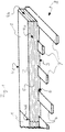
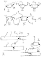
- FIG. 1 shows a schematic perspective view first embodiment of the invention. Are in the right part a parquet stick as plate element 1 and then to the left another plate element 1 shown, the only is partially shown.
- Each plate element 1 has one Top 2 and a bottom not visible in the illustration 3 and peripheral pages 4a, 4b, 4c and 4d.
- the peripheral pages 4a and 4c become the long sides and the peripheral sides The end faces are called 4b and 4d.
- the peripheral pages 4a, 4b, 4c and 4d are profiled. In Fig. 1 it is is a zigzag profile 5.
- recesses 6 which one to Groove opening narrowing cross section.
- alignment devices 7 burrs as alignment devices 7, the have a cross section corresponding to the recesses, so added that the plate elements 1 easily on the aligners 7 can be moved. Because of the Profiles of the recesses 6 and the alignment devices 7 is a form fit against movements of the plate elements 1 relative to the alignment devices 7 on the one hand in the direction perpendicular to the top 2 of the plate elements and the other in the direction parallel to the long sides (peripheral sides 4a and 4c), i.e. perpendicular to the end faces (peripheral sides 4b and 4d), the plate elements 1 created.
- each plate element 1 in its Bottom side 3 each with a half recess 6 'at the edge (see Fig. 3) and in the middle position a complete recess 6 has.
- the half recesses 6 ' i.e. the respective half grooves, are therefore also in the peripheral pages 4b and 4d, i.e. in the end faces, because the division, so to speak the groove in its longitudinal direction, i.e. parallel to the end faces took place.
- the two half recesses result 6 '(see FIG. 3) together an entire recess 6.
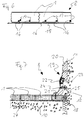
- FIGS. 1 and 2 have Embodiments that from the plate elements 1 above Burr strips different free protruding lengths. This is because ridges, i.e. Alignment devices 7 were used, which have different lengths. As a result, the connections of further burr strips or in general Alignment devices 7, which extend in the longitudinal direction connect so that further plate elements 1 are laid can, not all in one line, what the stability of the Laying system 8 increased.
- FIG. 3 are two assembled plate elements 1 in a schematic side view as a third embodiment a laying system 8 shown, so that the cross section the grooves or general recesses 6 are clear.
- the Recess 6 shown on the right lies entirely within a plate element 1.
- the left of the two recesses 6 is half each by a half recess 6 'in one Plate element 1 formed, which thereby when they are assembled form a complete recess 6.
- the recesses 6 have a dovetail groove Cross-section.
- the cross section could be general but also triangular, circular, oval or otherwise be as long as the interlocks are perpendicular and parallel to Top 2 of the plate elements 1 can be realized thereby.
- the recesses 6 extend in the thickness direction of the Plate elements 1, as in Fig. 3, but also Figs. 1 and 2, can be clearly seen, not even over half the thickness of the panel elements 1. This means that with this laying system 8 manufactured parquet floors are sanded down several times, without the recesses 6 by the removal of material the top 4a of the plate elements 1 can be reached, so that the combination of the Plate elements 1 over those contained in the recesses 6 Alignment devices 7 is maintained.
- This composite of the plate elements 1 on the in the recesses 6 contained alignment devices 7 is by the Profile 5 of the peripheral pages 4a, 4b, 4c and 4d supported. Only 4 are schematic examples in cross section Exemplary embodiments of different profiles 5 shown with which the peripheral sides 4a, 4b, 4c and 4d of Plate elements 1 can be provided. So the picture show I a crown profile, Figure II a cone profile, Figure III a deep wave profile, Figure IV a zigzag profile and Figure V a flat wave profile.
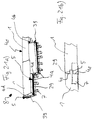
- FIG. 5 is in connection with a fourth embodiment of the laying system 8 to see a wall 11 in front of the plate elements 1 at a distance, each only partially are shown. Because of this distance there is between the wall 11 and the plate elements 1, a gap 12 that is required will when the plate elements 1 due to changes expand the ambient temperature and humidity, so that the plate elements 1 are not immediately on the Line 11 up.
- the gap 12 is thus an expansion joint.
- clamping devices 13 in the form of pressure media clamped in the present embodiment are formed by wooden springs 14.
- the wooden springs 14 are in pre-stressed state inserted in the gap 12 and act therefore the plate elements 1 towards each other. Shrink the plate elements 1 from their initial size or after an expansion, the clamping devices 13 press the Plate elements 1 together again, so that between the latter there are no gaps that are unattractive to look at, in which dirt can accumulate and pose a risk of stumbling.
- the tensioning devices 13 ensure that the loose or easily displaceable with the recesses 6 on the alignment devices 7, as in the previous embodiments Burr strips, pushed-on plate elements 1 safely be held together. Other types of attachment are not required.
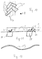
- tensioning devices 13 are another variant of the tensioning devices 13 in a further exemplary embodiment of a laying system 8 shown.
- These are tensioning straps 15 with claws 16, which is why the strap 15 are also called claw strap can.
- the tensioning strap 15 forms a tension element and runs under the laid plate elements 1 so that its claws 16 project upwards and into engagement openings 17, e.g. Relief cuts in the underside 3 of the plate elements 1 intervention.
- the claws 16 get caught due to their design in the engagement openings 17 so that they are fixed there are anchored.
- the tensioning strap 15 has an inherent elasticity on and is with claws hooked in the engagement openings 17 16 under tension so that it is the individual plate elements 1 towards each other.
- Such tensioning devices 13 can applied to partial areas of laid plate elements 1 and are therefore suitable for very large installation areas 9. 15 can be held together by means of straps for example, in turn, coupled by other straps and be held together.
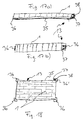
- Fig. 7 is an edge termination schematically in cross section a sixth embodiment of a laying system 8 is shown.
- Document 27 consists of a mat-like or preferably mesh-like Layer of or with preferably cork, rubber, caoutchouc, jute, Sisal, hemp, wool felt, coconut fibers, preferably a braided coconut fiber and particularly preferably one with rubber pressed or siliconized coconut fiber braid.
- the Pad 27 can from the bottom 3 of the plate elements 1 above alignment devices 7 only between the latter be provided, that is in the spaces formed between Substrate 10 and plate elements 1 and neighboring parallel alignment devices 7.
- the pad 27 can even if the alignment devices 7 are not from the undersides 3 of the plate elements 1 protrude down over the entire Laying surface 9 may be provided.
- Other design options for the pad 27 are air mattresses, Hose systems, mattresses, tube systems, etc.
- One preferably Design of a coconut fiber mat is coarse and about 3 to 6 mm thick.
- a laying system 8 as a floor covering Underlay 27 is particularly advantageous as impact sound insulation.
- the mesh can be large or small achieved a number of advantages. So this material is very resistant, flame-retardant, 100% moth-proof, rot-proof, moisture-resistant, electrostatically not chargeable, moisture regulating, fully biodegradable, and has high insulating properties against impact sound propagation and Heat loss as well as air chamber formation and air circulation, which ensures optimal ventilation of the underside of the parquet results.
- the aforementioned advantages can be fully or partially also with the other materials and embodiments mentioned achieve.
- any network form with Natural fibers, a rubber net, a coconut roll mat, a net with integrated braid, an air chamber or tube network, a full-surface thin air mattress, depending on the desired Vibration behavior of the floor can be inflated can, etc. used to exemplify just a few ways to call.
- the plate elements 1 laid on the base 27 end shortly before a wall 11, from which it is a gap or an expansion joint 12 separates, as can be seen in FIG. 7.
- tensioning devices 13 are used under prestress, so that they act on the plate elements 1 towards each other.
- clamping devices 13 are cork pieces here or strips 18 pressed into the gap 12.
- Cork pieces or strips 18 can be used as tensioning devices 13 for example, also foam rubber material, metal springs and the like are used that all serve the same purpose, namely that the plate elements 1 pressed together will.
- an edge strip 19 is also shown, the one Base bar 20, which in the edge region of the plate elements 1 are closest to the wall 11 on the plate elements 1 are, and contains an outer bar 21 which is on the wall 11 is attached.
- the attachment of the base bar 20 to the Plate elements 1 and the outer bar 21 on the wall 11 for example by screws (not designated), such as the representation in Fig. 7 can be seen.
- the baseboard 20 and the outer bar 21 are through their course Compensators 22 connected, the gap 23 between cover the base bar 20 and the outer bar 21.
- the reason for the gap 23 is the same as for the expansion joint 12 and lies in the fact that the plate elements 1 expand and can move in together. So that the expansion joint 12 is not visible is, the border 19 is provided. Through the compensation facilities 22 becomes the gap 23.
- the present exemplary embodiment is an elastic one Profile rubber, which has extensions that in the Base bar 20 and inserted into the outer bar 21.
- the base bar 20 Since the base bar 20 is firmly connected to the plate elements 1 , it can also be used to support tensioning devices 13 can be used against the wall, as in the embodiment 7 is shown. There is a clamping screw 24 screwed into the base bar 20 and is supported by a Spring element 25 against the wall 11, which is why the clamping screw 24 together with the spring element 25 also as a spring screw can be designated. Should that of the cork pieces or strips 18 and the spring element 25 applied force not to compress the plate elements 1 towards each other can be sufficient by screwing in the clamping screw 24 the compressive force in the area of the spring element 25 can be increased. In addition, a manual readjustment of the position, so to speak the parquet floor via the clamping screw 24.
- FIG. 8 Another embodiment is shown schematically in cross section in FIG. 8 for an edge closure of a laying system 8 shown. It can be seen that the wall 11 is closest lying plate element 1 was shortened so that it at all still between the penultimate plate element 1 and the wall 11 fits and so that the expansion joint 12 remains free. Furthermore, as alignment devices 7 and 7 'are a penultimate one Burr bar in front of wall 11 or a last burr bar shown in front of the wall 11. The last ridge (alignment devices 7 ') in front of the wall 11 in its longitudinal direction (Direction in the sheet plane) a distance from the penultimate Burr strip (alignment devices 7) in front of the wall 11.
- the e.g. plate elements made of solid material can with a corresponding arrangement of the alignment devices from the Initial strength almost to the strength of the alignment devices be sanded.
- This additional connection is supported the cohesion of the plate elements even after repeated Sanding, e.g. temporarily with parquet floors is common and necessary.
- Through the circumferential side profiles, such as. Waves, crown milling, zigzag, etc. can be there these profiles in particular the full strength of the panel elements capture, e.g. a parquet floor to a thickness approximately the alignment devices, such as ridge bars, be sanded without losing the strength of the connections the plate elements suffer significantly.
- All types of flooring, but also wall or ceiling coverings, can be made with the laying system where there are basically no material restrictions, so that wood, stone, metal, rubber, plastics etc. can be used. Because the plate elements are floating installed, they can be easily removed and removed can be reused, and the laying system can differ Purposes of use depending on the area of application and requirements are used: in sports halls on elastic substrates, in the exhibition stand for dismantling, in squash courts, in Rental area to take away when moving, etc. Other areas of application are e.g. Dance floors, floors for biologically pure build if only natural materials are used, Protective coverings or covers for high-quality floors, etc.
- Dovetail grooves can always be at the same distance and with half a recess on the end faces of the plate elements (Dovetail groove) can be such that there is an arrangement with subsequent plate elements offset by a groove width gives what the overall strength of the connection promotes.
- Dovetail groove When two end faces meet turn a full recess, such as Dovetail groove that with the following plate element again is solidified.
- the alignment devices which in particular contain burr strips can and run in the dovetail groove, hold the plate elements exactly in line.
- the underside of the plate elements can be a flat Area if there is no protrusion through the connection Ridge ledge / dovetail groove is present.
- the lateral and elongated drifting apart and the expansion / shrinking the panel elements can be used to form a laying surface surrounding wall through resilient material counteracted, such as wood springs, metal springs, Cork strips, foam rubber strips or other spring material, an insertion of these generally spring means under preload is particularly preferred.
- resilient material counteracted such as wood springs, metal springs, Cork strips, foam rubber strips or other spring material
- an insertion of these generally spring means under preload is particularly preferred.
- Alternatively or additionally can, if necessary, cause the individual to drift apart To prevent plate elements, even a continuous rubber band with pull claws e.g. in located on the bottom Relaxation joints are clawed.
- the alignment devices e.g. Ridges or dowels
- the ridges or general alignment devices are like this long so that the panel elements can be easily pushed open, such as for example boards. It is not meant to be one Canting and pinching can come.
- the beginning of laying the plate elements are made with different lengths Alignment devices.
- the final connection at the end of the laying can be through a straight groove as a recess on the bottom the plate elements, similar to the dovetail grooves are formed by such plate elements on a ridge put on and fastened with wooden nails.
- the last ridge bar can be a distance from the penultimate ridge bar have to have an agility one fastened with a wooden nail to enable the last plate element.
- the plate elements After completing the laying of the panel elements for formation e.g. a parquet or plank floor can the plate elements contracted, the edge of the plate elements exactly cut at a suitable distance from the wall so that a uniform expansion joint to one surrounding the laying surface Wall, and an elastic spacer (cork, Foam rubber, wooden or metal spring, etc.) can be incorporated, so that the plate elements cannot drift apart is and the plate elements are held together.
- an elastic spacer cork, Foam rubber, wooden or metal spring, etc.
- the installation system for manufacturing e.g. a solid wood floor, but also other floors with an expansion and contraction behavior depending on the ambient temperature and / or moisture, swelling and shrinking behavior, can the, between the plate elements and a
- the resulting joints become wider and thinner from a wall two-part or similar bar especially with one Expansion profile between the two last parts are covered.
- a special bar can also be used, the spacer screws to the wall to a changing distance of the To be able to correct plate elements to the wall. Fading and Expansion can also be done with wooden springs, metal springs, springy and / or pressing spacers can be corrected.
- a vapor barrier can be installed to protect against moisture will.
- impact sound insulation and compensation for small bumps of the substrate can be in mat, mesh or Mesh form materials that are as natural as possible, such as rubber, rubber, Coconut fiber, jute, sisal, hemp, cork, felt, wool felt and generally so-called geotextiles and all other than Suitable materials, but also wood storage or old ones Carpets, etc. be used.
- a major advantage of the laying system is that at any time and possible disassembly of the plate elements without great effort, by only using the tensioners applied tension takes away and the individual plate elements from the alignment devices (e.g. burr strips).
- Figure 9 shows exemplary profile shapes of the recesses 6 and the alignment devices 7, the strips, e.g. Ridges, and / or dowels can contain, by schematic Cross-sectional representations shown.
- Figure 1 shows one Dovetail cross-section, Figure II a triangular cross-section, Figure III a circular cross section, Figure IV an oval cross-section and Figure V a cut Circular cross-section, although other cross-sectional shapes are also suitable as long as they ensure the required positive locking, if this is not possible without a profile.
- FIG. 10 shows a further exemplary embodiment of a laying system 8 with plate elements running at an angle to one another 1 and alignment devices 7, which in turn as Degree bars are indicated. So far rectangular Orders have been specified or referred to, these details also apply to the present exemplary embodiment to implement.
- All conceivable laying patterns can be done with the laying system 8 can be realized, e.g. Herringbone pattern, Longstrip flooring, plank floors, and much more, but also any Shapes of the plate elements 1 can be used, such as Parquet strips or any plate shape.
- the preferred thickness the plate elements 1 is at least 6 mm, preferably at least 8 mm.
- the plate elements can also be multi-layered Plates, e.g. Panels of several layers of wood, coated cork or plastic plates, coated metal plates, Particle boards, laminated boards, linoleum boards etc. For large plate elements 1, it is preferable to continuous strips only dowels as alignment devices 7 to use.
- FIG. 11 Assembly of the laying system on beams 28 is shown in FIG. 11 shown.
- the alignment devices 7, for example be screwed to the beam 28.
- the alignment devices 7 before pushing on the plate elements 1, for example oiled or greased so that the sliding of the Plate elements 1 on the alignment devices 7 improved becomes. This means that even when using a possibly produced by means of the laying system 8 occurring noises, such as creaking or the like, are reduced.
- the first alignment devices 7 directly on a wall begin and the last aligners 7 not from that protrude penultimate plate element 1.
- the last plate element 1 in front of the wall will then be the size of the remaining one Space minus the expansion joint 12 cut and inserted.
- the alignment devices 7 can then e.g. from the first Plate element 1 are punched through so that they too extend into the recesses of the last plate element 1.
- edge pieces of the plate elements 1 that are so small that for example a ridge bar as alignment devices 7 cannot be used, e.g. Dowels inserted that are smaller than ridge bars to such To connect edge pieces with the adjacent plate elements 1.
- This pressure medium which can be seen in the figure in a top view a wave spring made of wood veneer in the position shown is inserted from above into an expansion joint 12.
- Such wave springs can be manufactured in a corrugation mold by in the wavy shape pressed together several layers of veneer will. After curing one between the veneer layers If the adhesive is inserted, the wavy shape is retained.
- FIG. 13 An alternative to the wave spring is shown in FIG. 13 in the form of a only a wooden spring consisting of a bow or a clasp 14.
- a wooden spring consisting of a bow or a clasp 14.
- the strengths of the veneer layers can also influence the spring force as well as the material of the veneer layers.
- we only preferred one total material thickness for wooden springs is about 4 to 8 mm.
- FIG. 14 show variants for steel springs 31.
- Figures I show a zigzag metal spring 31, II a metal spring 13 from a closed Metal band in oval shape, III an arch metal spring with wooden bearings 32 and IV a bow metal spring with bent End up.
- Fig. 15 it is shown how the one on one side of the Laying surface 9 missing wall 11 as an abutment for clamping devices 13 in the form of pressure medium firmly with the underground 10, for example, connected by screws 32 closure element 33 used as an abutment for the pressure medium can be.
- the clamping devices are in this variant Pieces or strips of cork 18.
- the installation system can 8 also contain a resilient bearing.
- a corresponding Variant is shown in FIG. 16.
- This is a tension band 35, which is longitudinal the undersides 3 of the plate elements 1 runs.
- bracket 36 and 36 'on On the edges of the outer plate elements 1 grab bracket 36 and 36 'on. With the bracket 36 on one side of the installation surface 9, the strap 35 is firmly connected.
- roller 37 with a ratchet 38 is attached, so that the roller 37 by actuating the ratchet 38 to wind the tensioning strap or belt 35 are rotated can, without them by the tensile force of the strap 35th turns back again, since the ratchet 38 has reached a winding position locked.
- This lock is preferably for dismantling of the laying system 9 releasable.
- the tension band 35 has in particular an inherent elasticity.
- the roller 37 with ratchet mechanism 38 can be in the expansion joint 12 or a separate one Recess of a wall.
- FIG. 18 An alternative embodiment of tensioning devices 13 in The shape of a tension band or strap 35 is shown in FIG. 18.
- the strap 35 runs around the free Circumferential sides of the plate elements lying on the laying surface 9 1.
- brackets 36 are arranged, but only for guiding of the strap 35 serve.
- a bracket 36 ' is arranged, which again, as in previously described embodiment, having a roller 37 a ratchet mechanism 38 to thereby tighten the strap 35 to tighten the installed plate elements 1 around.
- Figures I to IV of Fig. 20 show various positive locking devices 39, in particular on the end circumference sides can be provided by plate elements 1.
- Essential in the form-locking devices 39 is that they have undercuts included, so that a positive connection against movements perpendicular to the top 2 of the plate element 1.
- Alignment devices 7 in the form of dowels are shown in FIGS. 21a) and 21b) shown
- the plate elements connected by means of the dowels also have on their peripheral sides 4a, 4b, 4c, and 4d Profile 5.
- the profiles 5 on the end faces 4b and 4d are designed as positive locking devices 39, and the Profiles 5 on the long sides 4a and 4c serve as coupling devices 29.
Landscapes
- Engineering & Computer Science (AREA)
- Architecture (AREA)
- Civil Engineering (AREA)
- Structural Engineering (AREA)
- Life Sciences & Earth Sciences (AREA)
- Wood Science & Technology (AREA)
- Floor Finish (AREA)
- Road Paving Structures (AREA)
Abstract
Description
Claims (10)
- Verlegesystem mit Plattenelementen, die eine Ober- und eine Unterseite und dazwischenliegende Umfangsseiten aufweisen, in denen Ausnehmungen zur Aufnahme von Ausrichteinrichtungen zum formschlüssigen Verbinden von wenigstens zwei benachbart zu verlegenden Plattenelementen in Richtung senkrecht und in einer Richtung parallel zur Oberseite enthalten sind,
dadurch gekennzeichnet,daß die Ausnehmungen (6) und die Ausrichteinrichtungen (7) so dimensioniert sind, daß letztere locker verschiebbar in die Ausnehmungen (6) passen, unddaß Spanneinrichtungen (13) vorgesehen sind, mittels denen über die Ausrichteinrichtungen (7) miteinander verbundene Plattenelemente (1) aufeinander zu beaufschlagbar sind. - Verlegesystem nach Anspruch 1,
dadurch gekennzeichnet,daß die Ausrichteinrichtungen (7) Dübel und/oder Leisten enthalten, die zwischen zwei oder durchgehend über wenigstens zwei benachbart zu verlegenden Plattenelementen (1) in deren Ausnehmungen (6) einsetzbar sind,und/oderwobei vorzugsweise die Dübel und/oder Leisten ein Profil und insbesondere die Ausnehmungen (6) in den Plattenelementen (1) ein passendes Profil und/oder die Dübel und/oder Leisten maximal die halbe Dicke der Plattenelemente (1) aufweisen,
und/oderwobei ggf. Leisten bevorzugt Längen haben, die größer als die Abmessungen von zwei Plattenelementen (1) sind, durch die sie hindurch verlaufen, und insbesondere die Leisten unterschiedliche Längen haben,
und/oderwobei insbesondere die Dübel und/oder Leisten verjüngte Enden zur Einführung in die Ausnehmungen (6) haben,daß Plattenelemente (1) enthalten sind, die an ihren zu den in den Ausnehmungen (6) eingesetzten Ausrichteinrichtungen (7) parallelen Umfangsseiten (4a, 4b, 4c, 4d) Formschlußeinrichtungen (39) aufweisen, die einen Formschluß in Richtung senkrecht zu den in den Ausnehmungen (6) eingesetzten Ausrichteinrichtungen (7) mit einem benachbarten Plattenelement (1) ergeben, wie z.B. Schwalbenschwanz- oder Hakenausbildungen an einem Plattenelement (1) und entsprechende Nute am benachbarten Plattenelement (1). - Verlegesystem nach Anspruch 1 oder 2,
dadurch gekennzeichnet,daß die Ausnehmungen (6) in den Umfangsseiten (4a, 4b, 4c, 4d) der Plattenelemente (1) bohrlochartig mit rundem oder eckigem Profil ausgebildet und insbesondere näher bei deren Unterseiten (3) liegen,
oderdaß die Ausnehmungen (6) nutartig in den Unterseiten (3) offen und so profiliert sind, daß ein Formschluß zwischen in den Ausnehmungen (6) eingefügten Ausrichteinrichtungen (7) und Plattenelementen (1) in Richtung senkrecht zu deren Oberseiten (2) gewährleistet ist, bevorzugt in Form einer Schwalbenschwanznut, und sich insbesondere von der Unterseite (3) in Richtung zur Oberseite (2) der Plattenelemente (1) über nicht mehr als deren halbe Dicke erstrecken,
wobei vorzugsweise die Ausrichteinrichtungen (7) bevorzugt so dimensioniert sind, daß sie vollständig innerhalb der nutartigen Ausnehmungen (6) liegen und insbesondere mit der Unterseite (3) der Plattenelemente (1) eine plane Fläche bilden, oder über die Unterseite (3) der Plattenelemente (1) hinaus aus den nutartigen Ausnehmungen (6) vorstehen,
und/oderwobei insbesondere die Ausrichteinrichtungen (7) an einer Verlegefläche (9) befestigbar sind
und/oderwobei bevorzugt Elastikmittel vorgesehen sind, über die die Ausrichteinrichtungen (7) auf eine Verlegefläche (9) auflegbar sind. - Verlegesystem nach einem der vorhergehenden Ansprüche,
dadurch gekennzeichnet,daß die Umfangsseiten (4a, 4b, 4c, 4d) der Plattenelemente profiliert sind, so daß die Umfangsseitenprofile (5) benachbarter Plattenelemente (1) zusammenpassen,und/oderwobei bevorzugt die Profilierung (5) der Umfangsseiten (4a, 4b, 4c, 4d) der Plattenelemente (1) zusätzlich zu den Ausrichteinrichtungen (7) Kopplungseinrichtungen (29) ausbildet, wie z.B. Nut/Feder-Verbindungen, über die benachbarte Plattenelemente (1) verbindbar sinddaß weiter eine Unterlage (27) zum Auflegen der Plattenelemente (1) enthalten ist,wobei die Unterlage (27) insbesondere eine mattenartige oder bevorzugt netzartige Schicht aus oder mit Kork, Gummi, Kautschuk, Jute, Sisal, Hanf, Wollfilz, Kokosfasern, vorzugsweise einem Kokosfasergeflecht und besonders bevorzugt einem mit Kautschuk verpreßten oder silikonisierten Kokosfasergeflecht enthält. - Verlegesystem nach einem der vorhergehenden Ansprüche,
dadurch gekennzeichnet,daß die Spanneinrichtungen (13) enthalten:und/oderzwischen zwei über die Ausrichteinrichtungen (7) verbundenen, benachbarten und/oder nicht unmittelbar benachbarten Plattenelementen (1) einsetzbare Zugelemente, wie z.B. Klammern, Spannbänder u.dgl., die vorzugsweise über die und/oder an den Unterseiten (3) der Plattenelemente (1) führbar sind,
und/odervon außen auf wenigstens zwei über die Ausrichteinrichtungen (7) miteinander verbundenen Plattenelemente (1) auf deren Umfangsseiten (4a, 4b, 4c, 4d) wirkende Druckmittel, wie beispielsweise Holzfedern, Metallfedern, Korkteile, Moosgummiteile u.ä.,daß zweiteilige Randleisten (19) vorgesehen sind, die eine Grundleiste (20) zum Anbringen an Plattenelementen (1), eine Außenleiste (21) zum Anbringen an einem Rand der Verlegefläche (9) und Ausgleichseinrichtungen (22) enthalten, die zumindest an der Außenleiste (21) oder an der Grundleiste (20) angebracht sind und mittels denen bei einer Verschiebung der Plattenelemente (1) mit den Grundleisten (20) zwischen letzteren und den Außenleisten (21) auftretende Spalte (23) abdeckbar und/oder verschließbar sind. - Verlegesystem nach einem der vorhergehenden Ansprüche,
dadurch gekennzeichnet,daß das Material der Plattenelemente (1) und/oder der Ausrichteinrichtungen (7) ist oder enthält: Holz, Kork, Stein, Kunststoff, Verbundmaterial, Laminatmaterial, Kautschuk, Metall,
und/oderdaß die Plattenelemente eine längliche Form aufweisen, insbesondere stab-, latten- oder dielenartig sind, und die Ausnehmungen (6) quer zur Längsausdehnung der Plattenelemente (1) verlaufen,
und/oderdaß an zwei entgegengesetzten Umfangsseiten (4a, 4c; 4b, 4d) der Plattenelemente, vorzugsweise ggf. an den kürzeren Umfangsstirnseiten (4b, 4d), Formschlußeinrichtungen (39), wie z.B. jeweils eine Schwalbenschwanzfeder und ein Schwalbenschwanznut, vorgesehen sind, durch die zwei benachbarte Plattenelemente (1) passend und bevorzugt fest miteinander verbindbar sind. - Verlegesystem nach einem der vorhergehenden Ansprüche,
dadurch gekennzeichnet,daß,und/oderwenn die Ausnehmungen (6) nicht über das gesamte Plattenelement (1) hindurchgehend verlaufen, an den zwei entgegengesetzten Umfangsseiten der Plattenelemente (4a, 4b, 4c, 4d) liegende Ausnehmungen (6) nicht miteinander ausgerichtet angeordnet sind,
und,wenn die Ausnehmungen (6) über das gesamte Plattenelement (1) hindurchgehend verlaufen, die Ausnehmungen (6) bezüglich einer zu ihnen parallelen Mittellinie des Plattenelements (1) unsymmetrisch angeordnet sind oder in benachbart zu verlegenden Plattenelementen (1) senkrecht zu ihrer Verlaufsrichtung an unterschiedlichen Stellen liegen,daß jede in einer zu ihr parallel verlaufenden Umfangsseite (4b, 4d) des Plattenelementes (1) verlaufende Ausnehmung nur eine halbe Ausnehmung (6') ist. - Spanneinrichtungen für ein Verlegesystem, um benachbart verlegte Plattenelemente aufeinander zu zu beaufschlagen,
dadurch gekennzeichnet,daß die Spanneinrichtungen (13) von außen auf Umfangsseiten (4a, 4b, 4c, 4d) benachbart verlegter Plattenelemente (1) wirkende Druckmittel, wie beispielsweise Holzfedern, Metallfedern, Korkteile, Moosgummiteile u.ä., enthalten, die dazu ausgelegt sind, unter Vorspannung zwischen den Umfangsseiten (4a, 4b, 4c, 4d) verlegter Plattenelemente (1) und der Umgebung (Wand 11) der verlegten Plattenelemente (1) eingespannt zu werden, insbesondere so, daß die Druckmittel über einen Dehnungs- und Zusammenziehbereich der verlegten Plattenelemente (1) immer eine Vorspannung beibehalten. - Verlegeverfahren mit Plattenelementen, die eine Ober- und eine Unterseite und dazwischenliegende Umfangsseiten aufweisen, in denen Ausnehmungen enthalten sind, wobei zum Verbinden der Plattenelemente Ausrichteinrichtungen in die Ausnehmungen eingeführt werden,
dadurch gekennzeichnet,daß die Plattenelemente (1) locker auf die Ausrichteinrichtungen (7) geschoben werden,
unddaß über die Ausrichteinrichtungen (7) miteinander verbundene Plattenelemente (1) durch Spanneinrichtungen (13) aufeinander zu beaufschlagt werden. - Verlegeverfahren nach Anspruch 9,
dadurch gekennzeichnet,daß die Ausrichteinrichtungen (7) und/oder die Ausnehmungen (6) vor dem Zusammenfügen mit einem Gleitmittel, wie beispielsweise Seife, Öl, Wachs, etc., versehen werden,
und/oderdaß als Spanneinrichtungen (13)zwischen zwei über die Ausrichteinrichtungen (7) verbundene, benachbarte und/oder nicht unmittelbar benachbarte Plattenelemente (1) Zugelemente, wie z.B. Klammern, Spannbänder u.dgl., die vorzugsweise über die und/oder an den Unterseiten (3) der Plattenelemente (1) geführt werden, eingesetzt werden,
und/odervon außen auf wenigstens zwei über die Ausrichteinrichtungen (7) miteinander verbundene Plattenelemente (1) auf deren Umfangsseiten (4a, 4b, 4c, 4d) wirkende Druckmittel, wie beispielsweise Holzfedern, Metallfedern, Korkteile, Moosgummiteile u.ä. angebracht werden.
Priority Applications (2)
| Application Number | Priority Date | Filing Date | Title |
|---|---|---|---|
| AU27061/99A AU2706199A (en) | 1998-02-20 | 1999-02-22 | Laying system and tensioning devices for a floor-laying system and floor-laying method |
| PCT/AU1999/000104 WO1999042681A1 (en) | 1998-02-20 | 1999-02-22 | Laying system and tensioning devices for a floor-laying system and floor-laying method |
Applications Claiming Priority (2)
| Application Number | Priority Date | Filing Date | Title |
|---|---|---|---|
| DE19706777A DE19706777A1 (de) | 1996-08-16 | 1997-02-20 | Holzfußboden, Fußboden Verlegesytem für Parkett und andere Materialien ohne Klebstoff, Nagel, Schrauben, Klammern |
| DE19706777 | 1997-02-20 |
Publications (3)
| Publication Number | Publication Date |
|---|---|
| EP0860562A2 true EP0860562A2 (de) | 1998-08-26 |
| EP0860562A3 EP0860562A3 (de) | 1998-11-11 |
| EP0860562B1 EP0860562B1 (de) | 2007-07-25 |
Family
ID=7820964
Family Applications (1)
| Application Number | Title | Priority Date | Filing Date |
|---|---|---|---|
| EP98103044A Expired - Lifetime EP0860562B1 (de) | 1997-02-20 | 1998-02-20 | Fussboden sowie Verlegeverfahren |
Country Status (3)
| Country | Link |
|---|---|
| EP (1) | EP0860562B1 (de) |
| AT (1) | ATE368158T1 (de) |
| DE (1) | DE59814064D1 (de) |
Cited By (3)
| Publication number | Priority date | Publication date | Assignee | Title |
|---|---|---|---|---|
| WO2005047619A1 (fr) * | 2003-10-27 | 2005-05-26 | Gymnova S.A.S | Liaison de type mi-bois alterne pour l'assemblage de plaques de plancher demontables destine au spectacle et aux pratiques sportives |
| KR100616779B1 (ko) | 2004-08-14 | 2006-08-29 | 김기철 | 원목마루판의 조립구조 |
| CN112709412A (zh) * | 2020-12-24 | 2021-04-27 | 华睿企业管理咨询(衢州)有限公司 | 一种木塑地板生产用拼接成型设备 |
Citations (2)
| Publication number | Priority date | Publication date | Assignee | Title |
|---|---|---|---|---|
| GB376352A (en) | 1931-04-10 | 1932-07-11 | Charles Harry Hart | Improvements in or relating to wood block floors |
| DE800915C (de) | 1948-10-02 | 1950-12-14 | Ruberoidwerke Akt Ges | Parkettplatte |
Family Cites Families (7)
| Publication number | Priority date | Publication date | Assignee | Title |
|---|---|---|---|---|
| US3045294A (en) * | 1956-03-22 | 1962-07-24 | Jr William F Livezey | Method and apparatus for laying floors |
| SE450141B (sv) * | 1982-12-03 | 1987-06-09 | Jan Carlsson | Anordning for hopfogning av byggnadsplattor exv golvplattor |
| US4703601A (en) * | 1984-10-01 | 1987-11-03 | Abendroth Carl W | Fastener for flooring systems |
| DE3826307A1 (de) * | 1988-08-03 | 1990-02-08 | Gilde System Holzbau Gmbh | Bodenbelag fuer eine fuer sportzwecke zu benutzende halle sowie hierfuer geeignete bodenelemente |
| DE9202907U1 (de) * | 1992-03-05 | 1992-05-14 | Böckl, Karl, 8400 Regensburg | Wasserdichte Fußbodenleisten |
| AT397698B (de) * | 1992-03-12 | 1994-06-27 | Kaindl Holzindustrie | Halter |
| GB9222523D0 (en) * | 1992-10-27 | 1992-12-09 | Lonie William A | Improvements in and relating to flooring |
-
1998
- 1998-02-20 DE DE59814064T patent/DE59814064D1/de not_active Expired - Fee Related
- 1998-02-20 EP EP98103044A patent/EP0860562B1/de not_active Expired - Lifetime
- 1998-02-20 AT AT98103044T patent/ATE368158T1/de not_active IP Right Cessation
Patent Citations (2)
| Publication number | Priority date | Publication date | Assignee | Title |
|---|---|---|---|---|
| GB376352A (en) | 1931-04-10 | 1932-07-11 | Charles Harry Hart | Improvements in or relating to wood block floors |
| DE800915C (de) | 1948-10-02 | 1950-12-14 | Ruberoidwerke Akt Ges | Parkettplatte |
Cited By (3)
| Publication number | Priority date | Publication date | Assignee | Title |
|---|---|---|---|---|
| WO2005047619A1 (fr) * | 2003-10-27 | 2005-05-26 | Gymnova S.A.S | Liaison de type mi-bois alterne pour l'assemblage de plaques de plancher demontables destine au spectacle et aux pratiques sportives |
| KR100616779B1 (ko) | 2004-08-14 | 2006-08-29 | 김기철 | 원목마루판의 조립구조 |
| CN112709412A (zh) * | 2020-12-24 | 2021-04-27 | 华睿企业管理咨询(衢州)有限公司 | 一种木塑地板生产用拼接成型设备 |
Also Published As
| Publication number | Publication date |
|---|---|
| DE59814064D1 (de) | 2007-09-06 |
| ATE368158T1 (de) | 2007-08-15 |
| EP0860562A3 (de) | 1998-11-11 |
| EP0860562B1 (de) | 2007-07-25 |
Similar Documents
| Publication | Publication Date | Title |
|---|---|---|
| DE19940837A1 (de) | Verlegesystem und Verlegeverfahren | |
| DE69814867T2 (de) | Verfahren zum anbringen einer verkleidung bestehend aus brettern, latten oder ähnlichem und eine so hergestellte verkleidung | |
| EP2089596A1 (de) | Paneel sowie bodenbelag | |
| DE60312212T2 (de) | Bodenplatte und bodenabdeckung für elastischen boden | |
| EP2189589B1 (de) | Holzpaneelanordnung und Holzpaneel für diese Anordnung | |
| EP3202567B1 (de) | Verfahren zur herstellung eines als holz-beton-verbund ausgebildeten bauelements | |
| DE202007000310U1 (de) | Paneel sowie Bodenbelag | |
| EP0719953B1 (de) | Vorrichtung zum Höhenausgleich von Bauelementen | |
| DE202008000534U1 (de) | Profilschienensystem zum Abdecken mindestens eines Belagrandes | |
| EP0860562B1 (de) | Fussboden sowie Verlegeverfahren | |
| DE102016001185A1 (de) | Als Holz-Beton-Verbund ausgebildetes Bauelement sowie Verfahren zu dessen Herstellung | |
| EP2357299B1 (de) | Fußbodenpaneel | |
| WO2013160313A1 (de) | Leichtbauplatte | |
| WO2017017144A1 (de) | Wandkonstruktion und verfahren zum montieren | |
| AT1025U1 (de) | Bauelement sowie damit hergestellte wandverkleidung | |
| DE19918878A1 (de) | Verlegesystem und Verlegeverfahren | |
| DE102008003117B4 (de) | Einrichtung zum Verriegeln zweier Bauplatten | |
| DE202004004107U1 (de) | Belag, bestehend aus einzelnen Platten aus mineralischem Material | |
| EP1700966A1 (de) | Flachdübelverbinder zur Fixierung nebeneinander angeordneter lattenförmiger Holzelemente | |
| DE2440289C3 (de) | Bodenbelag | |
| DE29507600U1 (de) | Vorrichtung zum Höhenausgleich von Bauelementen | |
| DE8615282U1 (de) | Gipsbauplatte | |
| DE102011012023A1 (de) | Verbindungselement zur Verbindung von flächigen Bauteilen | |
| EP1799926B1 (de) | Gebäudedach sowie dämmschichtaufbau und mineralfaserdämmstoffelement für ein gebäudedach | |
| EP2080845A1 (de) | Holzfertigbauelement |
Legal Events
| Date | Code | Title | Description |
|---|---|---|---|
| PUAI | Public reference made under article 153(3) epc to a published international application that has entered the european phase |
Free format text: ORIGINAL CODE: 0009012 |
|
| AK | Designated contracting states |
Kind code of ref document: A2 Designated state(s): AT BE CH DE DK ES FI FR GB GR IE IT LI LU NL PT SE |
|
| AX | Request for extension of the european patent |
Free format text: AL;LT;LV;MK;RO;SI |
|
| PUAL | Search report despatched |
Free format text: ORIGINAL CODE: 0009013 |
|
| AK | Designated contracting states |
Kind code of ref document: A3 Designated state(s): AT BE CH DE DK ES FI FR GB GR IE IT LI LU MC NL PT SE |
|
| AX | Request for extension of the european patent |
Free format text: AL;LT;LV;MK;RO;SI |
|
| AKX | Designation fees paid | ||
| 17P | Request for examination filed |
Effective date: 19990511 |
|
| RBV | Designated contracting states (corrected) |
Designated state(s): AT BE CH DE DK ES FI FR GB IE LI LU NL PT SE |
|
| RBV | Designated contracting states (corrected) |
Designated state(s): AT BE CH DE DK ES FI FR GB GR IE IT LI LU NL PT SE |
|
| TPAD | Observations filed by third parties |
Free format text: ORIGINAL CODE: EPIDOS TIPA |
|
| 17Q | First examination report despatched |
Effective date: 20020506 |
|
| GRAP | Despatch of communication of intention to grant a patent |
Free format text: ORIGINAL CODE: EPIDOSNIGR1 |
|
| RTI1 | Title (correction) |
Free format text: FLOOR AS WELL AS METHOD OF LAYING |
|
| GRAS | Grant fee paid |
Free format text: ORIGINAL CODE: EPIDOSNIGR3 |
|
| GRAA | (expected) grant |
Free format text: ORIGINAL CODE: 0009210 |
|
| AK | Designated contracting states |
Kind code of ref document: B1 Designated state(s): AT BE CH DE DK ES FI FR GB GR IE IT LI LU NL PT SE |
|
| REG | Reference to a national code |
Ref country code: GB Ref legal event code: FG4D Free format text: NOT ENGLISH |
|
| REG | Reference to a national code |
Ref country code: CH Ref legal event code: EP |
|
| REG | Reference to a national code |
Ref country code: IE Ref legal event code: FG4D Free format text: LANGUAGE OF EP DOCUMENT: GERMAN |
|
| REF | Corresponds to: |
Ref document number: 59814064 Country of ref document: DE Date of ref document: 20070906 Kind code of ref document: P |
|
| REG | Reference to a national code |
Ref country code: CH Ref legal event code: NV Representative=s name: BRAUNPAT BRAUN EDER AG |
|
| PG25 | Lapsed in a contracting state [announced via postgrant information from national office to epo] |
Ref country code: PT Free format text: LAPSE BECAUSE OF FAILURE TO SUBMIT A TRANSLATION OF THE DESCRIPTION OR TO PAY THE FEE WITHIN THE PRESCRIBED TIME-LIMIT Effective date: 20071226 Ref country code: NL Free format text: LAPSE BECAUSE OF FAILURE TO SUBMIT A TRANSLATION OF THE DESCRIPTION OR TO PAY THE FEE WITHIN THE PRESCRIBED TIME-LIMIT Effective date: 20070725 Ref country code: FI Free format text: LAPSE BECAUSE OF FAILURE TO SUBMIT A TRANSLATION OF THE DESCRIPTION OR TO PAY THE FEE WITHIN THE PRESCRIBED TIME-LIMIT Effective date: 20070725 Ref country code: ES Free format text: LAPSE BECAUSE OF FAILURE TO SUBMIT A TRANSLATION OF THE DESCRIPTION OR TO PAY THE FEE WITHIN THE PRESCRIBED TIME-LIMIT Effective date: 20071105 |
|
| NLV1 | Nl: lapsed or annulled due to failure to fulfill the requirements of art. 29p and 29m of the patents act | ||
| GBV | Gb: ep patent (uk) treated as always having been void in accordance with gb section 77(7)/1977 [no translation filed] |
Effective date: 20070725 |
|
| REG | Reference to a national code |
Ref country code: IE Ref legal event code: FD4D |
|
| EN | Fr: translation not filed | ||
| PG25 | Lapsed in a contracting state [announced via postgrant information from national office to epo] |
Ref country code: GR Free format text: LAPSE BECAUSE OF FAILURE TO SUBMIT A TRANSLATION OF THE DESCRIPTION OR TO PAY THE FEE WITHIN THE PRESCRIBED TIME-LIMIT Effective date: 20071026 |
|
| PG25 | Lapsed in a contracting state [announced via postgrant information from national office to epo] |
Ref country code: IE Free format text: LAPSE BECAUSE OF FAILURE TO SUBMIT A TRANSLATION OF THE DESCRIPTION OR TO PAY THE FEE WITHIN THE PRESCRIBED TIME-LIMIT Effective date: 20070725 Ref country code: GB Free format text: LAPSE BECAUSE OF FAILURE TO SUBMIT A TRANSLATION OF THE DESCRIPTION OR TO PAY THE FEE WITHIN THE PRESCRIBED TIME-LIMIT Effective date: 20070725 |
|
| PLBE | No opposition filed within time limit |
Free format text: ORIGINAL CODE: 0009261 |
|
| STAA | Information on the status of an ep patent application or granted ep patent |
Free format text: STATUS: NO OPPOSITION FILED WITHIN TIME LIMIT |
|
| PG25 | Lapsed in a contracting state [announced via postgrant information from national office to epo] |
Ref country code: SE Free format text: LAPSE BECAUSE OF FAILURE TO SUBMIT A TRANSLATION OF THE DESCRIPTION OR TO PAY THE FEE WITHIN THE PRESCRIBED TIME-LIMIT Effective date: 20071025 |
|
| 26N | No opposition filed |
Effective date: 20080428 |
|
| PG25 | Lapsed in a contracting state [announced via postgrant information from national office to epo] |
Ref country code: FR Free format text: LAPSE BECAUSE OF FAILURE TO SUBMIT A TRANSLATION OF THE DESCRIPTION OR TO PAY THE FEE WITHIN THE PRESCRIBED TIME-LIMIT Effective date: 20080321 |
|
| BERE | Be: lapsed |
Owner name: BOCKL, KARL Effective date: 20080228 |
|
| PG25 | Lapsed in a contracting state [announced via postgrant information from national office to epo] |
Ref country code: BE Free format text: LAPSE BECAUSE OF NON-PAYMENT OF DUE FEES Effective date: 20080228 |
|
| PGFP | Annual fee paid to national office [announced via postgrant information from national office to epo] |
Ref country code: AT Payment date: 20090219 Year of fee payment: 12 |
|
| PGFP | Annual fee paid to national office [announced via postgrant information from national office to epo] |
Ref country code: CH Payment date: 20090227 Year of fee payment: 12 |
|
| PGFP | Annual fee paid to national office [announced via postgrant information from national office to epo] |
Ref country code: DE Payment date: 20090430 Year of fee payment: 12 |
|
| PG25 | Lapsed in a contracting state [announced via postgrant information from national office to epo] |
Ref country code: DK Free format text: LAPSE BECAUSE OF FAILURE TO SUBMIT A TRANSLATION OF THE DESCRIPTION OR TO PAY THE FEE WITHIN THE PRESCRIBED TIME-LIMIT Effective date: 20070725 |
|
| PG25 | Lapsed in a contracting state [announced via postgrant information from national office to epo] |
Ref country code: LU Free format text: LAPSE BECAUSE OF NON-PAYMENT OF DUE FEES Effective date: 20080220 |
|
| REG | Reference to a national code |
Ref country code: CH Ref legal event code: PL |
|
| PG25 | Lapsed in a contracting state [announced via postgrant information from national office to epo] |
Ref country code: LI Free format text: LAPSE BECAUSE OF NON-PAYMENT OF DUE FEES Effective date: 20100228 Ref country code: CH Free format text: LAPSE BECAUSE OF NON-PAYMENT OF DUE FEES Effective date: 20100228 |
|
| PG25 | Lapsed in a contracting state [announced via postgrant information from national office to epo] |
Ref country code: AT Free format text: LAPSE BECAUSE OF NON-PAYMENT OF DUE FEES Effective date: 20100220 |
|
| PG25 | Lapsed in a contracting state [announced via postgrant information from national office to epo] |
Ref country code: IT Free format text: LAPSE BECAUSE OF NON-PAYMENT OF DUE FEES Effective date: 20080229 Ref country code: DE Free format text: LAPSE BECAUSE OF NON-PAYMENT OF DUE FEES Effective date: 20100901 |