EP0858563B1 - Dispositif de serrage dote d'un palier a friction conique et destine a des moyens de traction - Google Patents
Dispositif de serrage dote d'un palier a friction conique et destine a des moyens de traction Download PDFInfo
- Publication number
- EP0858563B1 EP0858563B1 EP96946363A EP96946363A EP0858563B1 EP 0858563 B1 EP0858563 B1 EP 0858563B1 EP 96946363 A EP96946363 A EP 96946363A EP 96946363 A EP96946363 A EP 96946363A EP 0858563 B1 EP0858563 B1 EP 0858563B1
- Authority
- EP
- European Patent Office
- Prior art keywords
- tension arm
- sliding bearing
- tensioning device
- support
- bearing surfaces
- Prior art date
- Legal status (The legal status is an assumption and is not a legal conclusion. Google has not performed a legal analysis and makes no representation as to the accuracy of the status listed.)
- Expired - Lifetime
Links
- 238000006243 chemical reaction Methods 0.000 claims abstract description 7
- 239000000314 lubricant Substances 0.000 claims description 9
- 239000000463 material Substances 0.000 claims description 5
- 238000001746 injection moulding Methods 0.000 claims description 3
- 230000006835 compression Effects 0.000 claims description 2
- 238000007906 compression Methods 0.000 claims description 2
- 230000002093 peripheral effect Effects 0.000 claims 4
- 238000013016 damping Methods 0.000 description 6
- 229920001971 elastomer Polymers 0.000 description 4
- 239000000806 elastomer Substances 0.000 description 4
- 238000000034 method Methods 0.000 description 4
- 238000006073 displacement reaction Methods 0.000 description 2
- 230000000694 effects Effects 0.000 description 2
- 230000002349 favourable effect Effects 0.000 description 2
- 230000036316 preload Effects 0.000 description 2
- 238000005507 spraying Methods 0.000 description 2
- 229910000838 Al alloy Inorganic materials 0.000 description 1
- 238000010276 construction Methods 0.000 description 1
- 238000004512 die casting Methods 0.000 description 1
- 238000005516 engineering process Methods 0.000 description 1
- 230000007774 longterm Effects 0.000 description 1
- 239000007921 spray Substances 0.000 description 1
- 238000004804 winding Methods 0.000 description 1
Images

Classifications
-
- F—MECHANICAL ENGINEERING; LIGHTING; HEATING; WEAPONS; BLASTING
- F16—ENGINEERING ELEMENTS AND UNITS; GENERAL MEASURES FOR PRODUCING AND MAINTAINING EFFECTIVE FUNCTIONING OF MACHINES OR INSTALLATIONS; THERMAL INSULATION IN GENERAL
- F16H—GEARING
- F16H7/00—Gearings for conveying rotary motion by endless flexible members
- F16H7/08—Means for varying tension of belts, ropes, or chains
- F16H7/10—Means for varying tension of belts, ropes, or chains by adjusting the axis of a pulley
- F16H7/12—Means for varying tension of belts, ropes, or chains by adjusting the axis of a pulley of an idle pulley
- F16H7/1209—Means for varying tension of belts, ropes, or chains by adjusting the axis of a pulley of an idle pulley with vibration damping means
- F16H7/1218—Means for varying tension of belts, ropes, or chains by adjusting the axis of a pulley of an idle pulley with vibration damping means of the dry friction type
-
- F—MECHANICAL ENGINEERING; LIGHTING; HEATING; WEAPONS; BLASTING
- F16—ENGINEERING ELEMENTS AND UNITS; GENERAL MEASURES FOR PRODUCING AND MAINTAINING EFFECTIVE FUNCTIONING OF MACHINES OR INSTALLATIONS; THERMAL INSULATION IN GENERAL
- F16H—GEARING
- F16H7/00—Gearings for conveying rotary motion by endless flexible members
- F16H7/08—Means for varying tension of belts, ropes, or chains
- F16H2007/0802—Actuators for final output members
- F16H2007/081—Torsion springs
-
- F—MECHANICAL ENGINEERING; LIGHTING; HEATING; WEAPONS; BLASTING
- F16—ENGINEERING ELEMENTS AND UNITS; GENERAL MEASURES FOR PRODUCING AND MAINTAINING EFFECTIVE FUNCTIONING OF MACHINES OR INSTALLATIONS; THERMAL INSULATION IN GENERAL
- F16H—GEARING
- F16H7/00—Gearings for conveying rotary motion by endless flexible members
- F16H7/08—Means for varying tension of belts, ropes, or chains
- F16H2007/0889—Path of movement of the finally actuated member
- F16H2007/0893—Circular path
Definitions
- the present invention relates to a tensioning device for traction devices such as Belts and chains, with a tensioning means, preferably tensioning pulley load-bearing, spring-loaded tension arm against a stationary element is rotatably mounted by means of a plain bearing, the plain bearing surfaces as parallel to each other and concentric to the tension arm axis arranged cone surfaces are formed, and with one along the clamping arm axis tortuous, on the one hand on a tension arm-fixed support and on the other helical torsion spring supported on a fixed support.
- a tensioning means preferably tensioning pulley load-bearing, spring-loaded tension arm against a stationary element is rotatably mounted by means of a plain bearing, the plain bearing surfaces as parallel to each other and concentric to the tension arm axis arranged cone surfaces are formed, and with one along the clamping arm axis tortuous, on the one hand on a tension arm-fixed support and on the other helical torsion spring supported on a fixed support.
- Such a tensioning device is for example in US-A 46 98 049 disclosed.
- the tension arm axis and the stationary element each have a conical surface on, with a tapered plain bearing bush between these two tapered surfaces is arranged.
- the tapered plain bearing surfaces of Hand pushed towards each other and positioned axially until the Radial play in the plain bearing is again within a permissible high tolerance range.
- US 44 72 162 A discloses a belt tensioner in which the tension arm is pivotally mounted on an axis by means of a radial sliding bearing. Of the The tension arm is spring-loaded against the belt using a helical torsion spring. A conical elastomer part is provided at the free end of the axle, whose conical outer surface on a conical inner surface of the tension arm. The elastomer part is placed on the axle. The The elastomer part is under tension between the tension arm due to friction between the inner cylindrical surface of the elastomer part and the outer cylindrical surface of the axis. If on that cylindrical slide bearing abrasive wear occurs, there is a risk of undesirable bearing play. Adjustment of the plain bearing is due to the cylindrical shape of the plain bearing surfaces is not possible.
- the tapered plain bearing bush between these conical surfaces is provided, the plain bearing bush can also loosely in between be arranged.
- Plain bearing surfaces regularly create sliding friction between the outer tapered Shell surface of the plain bearing bush and the adjacent fixed or tension arm-fixed Adjust the cone area.
- US-A 4698049 further discloses a damping device which Damping pivoting movements of the clamping arm relative to the stationary element.
- This damping device is formed in that the stationary element and the tension arm axis with mutually facing end faces arranged on the end face is provided, with a friction disc between these end faces plan end faces is provided.
- the one assigned to the fixed element The end face is formed on a separate disc.
- Clamping device is a damping device created without In contrast to the known tensioning device, additional measures have been taken Need to become. The sliding friction between the plain bearing surfaces is due to the Reactive force or the associated surface pressure increased so that the desired damping effect in both directions of rotation of the clamping arm entry.
- a helical torsion spring clamped, for example, under axial pressure is a particularly advantageous arrangement of the supports and the sliding bearing surfaces given when the slide bearing surface assigned to the tension arm radially outside and the plain bearing surface assigned to the stationary element radially is arranged inside, in the direction of the tapered ends of the plain bearing surfaces towards the extended ends of the plain bearing surfaces stationary support and then the tension arm-fixed support is located. If the Helical torsion spring is clamped under axial pressure, i.e.
- an axial Exerting pressure is an arrangement that is as simple as it is expedient created in that the slide bearing surface associated with the tensioning arm is radial inside and the plain bearing surface assigned to the stationary element radially outside is located, in the direction of the tapered ends of the plain bearing surfaces towards the extended ends of the plain bearing surfaces, the tension arm-fixed first Support and then the stationary support is arranged.
- both described Arrangements result in the one arranged perpendicular to the slide bearing surfaces Reactive power in an advantageous manner without there being any additional Components or measures required.
- Clamping devices according to the invention are often used for unit drive used by engines of motor vehicles. In the construction of such Among other things, the clamping devices also require space.
- a particularly space-saving variant is created in that the tension arm-resistant Clamping arm axis radially inside the plain bearing a helical torsion spring Receiving axially open recess having the stationary support is radially overlapped. This variant is therefore special makes sense because the radially outer slide bearing is enlarged due to the circumferential side Plain bearing surfaces have a reduced surface pressure and thus reduced abrasive wear.
- a clamping device which is particularly advantageous with regard to assembly exists in that the tension arm-fixed tension arm axis in the cup-shaped, a pot base, a pot jacket and a pot lid with stationary Element is arranged, the stationary support through the pot lid is formed, and wherein a circumferentially formed slot on the stationary element is provided, through which the clamping arm is guided radially is.
- the pot lid can e.g. by means of a bayonet catch on the fixed element to be attached.
- Another variant is on one with a cylindrical outer Shell surface provided end of the stationary tension arm axis preferably releasably arranged at this end, with a conical outer surface and cylindrical inner surface provided cone bushing. Their tapered end is an end of the tension arm axis facing away from the tension arm facing, the clamping arm axis with a coaxial through hole is provided. This ensures that the one with the tension arm axis Coaxial tapered bore provided with the preferred arm integral with it the clamping arm axis together with the taper bush and the helical torsion spring can be placed on the tension arm axis.
- the tension arm or The taper bush is secured against axial sliding off the tension arm axis;
- Clamping arm axis coaxial screw must be screwed into the clamping arm end, wherein the cone bushing with its one end face on the screw head axially is supported. It can be useful that this screw through the coaxial Through hole of the tension arm axis passed and into the engine block is screwed into it.
- the screw fulfills two Functions, namely firstly the attachment of the tension arm axis to the engine block and second, the axial securing of the tension arm or the taper bush.
- the stationary element preferably has a tapered bore, the extended one End facing the tension arm.
- the preferably in one piece with the Clamping arm axis is inserted into the tapered bore, the free end of which axially projects beyond this conical bore.
- the support disk is preferably pressed on. In this case it needs Support disc against axial displacement on the clamping arm axis not particularly to be secured.
- the tapered bore wall of the tapered bore forms in in this case the one plain bearing surface.
- the taper bush does not have to be a separate component. It can also be expedient that arranged on one with distributed over the circumference Breakthroughs provided jacket to form a plain bearing bush in Spray process on the sleeve sprayed plain bearing material the breakthroughs penetrates and reaches behind. In this way there is an intimate connection for example, created between the tension arm axis and the plain bearing bush.
- At least one plain bearing surface is provided with lubricant pockets distributed over the circumference.
- the lubricant is poured into the lubricant pockets, so that one long-term optimal damping and sliding properties guaranteed are.
- the lubricant pockets can of course also be on a plain bearing bush be provided.
- both Ends of the helical torsion spring are firmly clamped. That way ensures that no radial forces act under the torsion of the spring the plain bearing are initiated and there undesirable edge loads cause.
- This clamping can also be achieved when on both ends of the coil spring under their torsion one each across Force acting on the longitudinal axis of the helical torsion spring. This is for example, the case when the spring due to its torsion with its angled end is supported on a first base fixed to the tension arm, where the one supporting force acts on one of the pairs of forces.
- the helical torsion spring lies on a second one Base, where the second supporting force of the one pair of forces acts there.
- the other pair of forces is formed in an analogous manner at fixed bases. This also ensures that due to the clamped helical torsion spring no further radial forces act on the slide bearing.
- the extended ends of the Plain bearing preferably facing the tension arm.
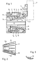
- a tensioning arm 1 is provided, on which a tensioning roller 2 is fastened for contact with a traction means, not shown.
- the tension arm 1 is rotatably supported by a slide bearing 3 relative to a housing 4.
- a clamping arm axis 5 formed in one piece with the clamping arm 1 has a conical outer lateral surface 6.
- the clamping arm axis 5 is inserted into a conical bore 8 of the housing 4 provided with a conical wall 7, a plain bearing bushing 9 being provided between the conical wall 7 parallel to the conical outer lateral surface 6.
- a projection 10 of the slide bearing bush 9 engages in a recess 11 of the tension arm axis 5.
- the cone wall 7 and the outer conical outer surface 12 of the slide bearing bush 9 form slide bearing surfaces for the rotatable mounting of the tension arm 1 relative to the housing 4. With its end facing away from the tension arm 1, the tension arm axis 5 projects beyond the cone bore 7, a support disk 13 being pressed onto this end of the tension arm .
- the support disk 13 can of course also be connected to the tension arm 1 in a form-fitting or material-locking manner.
- a helical torsion spring 14 is arranged coaxially to the tensioning arm axis 5 and clamped on the one hand on a support 15 provided on the support disk 13 and on the other hand on a support 16 provided on the housing, the housing 4 with exertion of a torsional force and an axial compressive force F D.
- the extended ends of the slide bearing surfaces 7, 12 face the tensioning arm 1, with the tension arm-fixed support 15 and then the housing-fixed support 16 being arranged in the direction from the tapered ends of the slide bearing surfaces 7, 12 toward the extended ends of the slide bearing surfaces 7, 12.
- the tension arm 1 and the tension arm axis 5 formed in one piece with it are preferably produced in a die casting process, an aluminum alloy being a suitable material.
- Figures 2 and 3 show as a detail the plain bearing bush 9 and the attached trained projection 10, wherein the tapered outer surface 12 with Lubricant pockets 16a is provided for receiving lubricant.
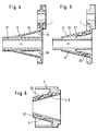
- FIG 4 shows a modified version of the one-piece with the clamping arm axis 5 connected tension arm 1.
- the tension arm axis 5 here consists of a cylindrical tube 17, the plain bearing bushing 9 on the cylindrical tube 17 is applied by spraying.
- the conical outer one Shell surface 12 selected as a sliding bearing surface.
- the exemplary embodiment according to FIG. 7 is essentially the same as that according to FIG largely corresponds to that of FIG.
- Different from the embodiment described above is the one here to form the tension arm-resistant support Support disc 13 facing the end of the helical torsion spring 14 in a Clamp arm axis 5 provided groove 24 clamped, the support disc 13th engages in this groove 24 and axially supports the helical torsion spring 14.
- the plain bearing bush 9 can be compared to the Cone wall 7 and opposite the conical outer surface 6 of the Turn the tension arm axis 5 freely.
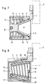
- the exemplary embodiment according to the invention shown in FIG. 8 differs differs essentially from the previous exemplary embodiments characterized in that the clamping arm axis 5 with a coaxial to the clamping arm 1 out axially open recess 25 is provided, in which the helical torsion spring 14th is arranged.
- the cup-shaped housing 4 has a pot bottom 26 and a pot jacket 27, with the stationary support on a pot lid 28 is formed, the cover jacket 29 axially overlaps the pot jacket 27 and attached to it.
- a slot 30 is formed in the circumferential direction provided on the pot jacket 27 or on the pot lid 28 through which the Clamping arm 1 is passed radially.
- the helical torsion spring 14 is on the other hand supported on a bottom 31 of the tension arm axis 5.
- a stationary clamping arm axis 32 is provided.
- the clamping arm axis 32 is provided on the one hand with a support flange 33 which is provided for contact with an engine block, not shown.
- a clamping arm 35 is rotatably supported by means of a slide bearing 36.
- the tension arm 35 has a tension arm jacket which is coaxial with the tension arm axis 32 37 with a tapered bore 38, the tapered end of the tapered bore 38 faces away from the tension arm 35.
- a cone bushing 39 is arranged between the tension arm jacket 37 and the clamping arm axis 32.
- This Taper bush 39 has a conical outer surface 40 and a cylindrical inner lateral surface 41.
- a tapered plain bearing bush 42 is provided between the taper bush 39 and the Clamping arm jacket 37.
- the Slide bearing bush 42 and the taper bush 39 can of course also be made in one piece, for example by injection molding from plastic. Sliding movements take place here between the cone wall 43 of the cone bore 38 and an outer conical lateral surface 44 of the conical plain bearing bush 42 instead of.
- a coaxially arranged helical torsion spring 45 is on the one hand Support flange 33 and on the other hand on a tension arm-fixed support 46 below Exerted an axial compressive force and a torsional force.
- the clamping arm axis 32 is provided with a coaxial through hole 47, a screw 48 is passed through the through hole 47 and is screwed to the engine block, not shown. It goes without saying possible between the screw head 49 and the screw head 49 facing the end face of the plain bearing bush 42 to provide a washer. In this way it is ensured that the plain bearing bush 42 of the Clamping arm axis 32 cannot slide axially.
- FIG. 10 shows a cross section of the tensioning device according to the invention according to FIG. 9, but without the screw 48.
- the support which is fixed to the tension arm, can be clearly seen here.
- the angled end of the helical torsion spring 45 engages in an opening 50 of the support flange 33 and is supported on the circumference thereof.
- the winding 51 of the helical torsion spring 45 adjoining this end lies at points on the tension arm axis 32.
- Support forces F S which together form a pair of forces, act on these two systems. If the stationary support for the helical torsion spring is formed in an analogous manner, it is evidently ensured that no radially acting force generated from the torsion of the helical torsion spring 45 acts on the slide bearing.
- the supports of the helical torsion spring explained on the basis of the exemplary embodiment according to FIGS. 9 and 10 are of course also expedient for the other exemplary embodiments in the same advantageous manner.
Claims (14)
- Dispositif tendeur pour des moyens de traction tels que des courroies ou des chaínes comprenant un bras tendeur (1, 35), suspendu par ressort par rapport au moyen de traction et portant un moyen de tension, de préférence un galet tendeur (2), ce bras étant monté en rotation par un palier lisse (3, 36) sur un élément fixe (4, 32), les surfaces (7, 12, 43, 44) du palier lisse étant coniques, parallèles, concentriques à l'axe du bras tendeur (5, 32), ainsi qu'un ressort hélicoïdal (14, 15) enroulé le long de l'axe du bras tendeur (5, 32), et appuyé par une extrémité contre un appui (15, 46) solidaire du bras tendeur et par l'autre extrémité contre un appui fixe (16, 33),
caractérisé en ce queune précontrainte axiale est appliquée au ressort hélicoïdal de compression, à l'état monté, en plus de la précontrainte de torsion,le ressort hélicoïdal (14, 45) tendu entre les appuis (15, 16, 33, 46) exerce une force axiale (FD), induisant sa force axiale (FD) comme force de réaction (FR) perpendiculaire aux surfaces de palier lisse (7, 12, 43, 44) dans le palier lisse (3, 36) pour que les surfaces de glissement (7, 12, 43, 44) du palier lisse soient pressées l'une contre l'autre par la force axiale (FD). - Dispositif tendeur selon la revendication 1,
caractérisé en ce que
le ressort hélicoïdal (14, 45) exerce une poussée axiale (FD). - Dispositif tendeur selon la revendication 2,
caractérisé en ce que
la surface de palier lisse (43) associée au bras tendeur (35) est dirigée radialement vers l'extérieur et la surface de palier lisse (44) associée à l'élément fixe (32) est radialement à l'intérieur, et en direction allant des extrémités diminuées vers les extrémités élargies des surfaces de palier lisse (43, 44), on a tout d'abord l'appui fixe (33) puis l'appui (46) solidaire du bras tendeur. - Dispositif tendeur selon la revendication 2,
caractérisé en ce que
la surface de palier lisse (12) associée au bras tendeur (1) est située radialement à l'intérieur et la surface de palier lisse (7) associée à l'élément fixe (4) est située radialement à l'extérieur, et en direction allant des extrémités diminuées vers les extrémités élargies des surfaces de palier lisse (7, 12), on a tout d'abord l'appui (13, 15) solidaire du bras tendeur puis l'appui fixe (16). - Dispositif tendeur selon la revendication 1,
caractérisé en ce que
l'axe (5) solidaire du bras tendeur comporte radialement à l'intérieur du palier lisse (3), une cavité (25) ouverte axialement et recevant le ressort hélicoïdal (14), cette cavité étant chevauchée radialement par l'appui fixe (16, 28). - Dispositif tendeur selon la revendication 5,
caractérisé en ce que
l'axe (5) solidaire du bras tendeur est logé dans l'élément (4) en forme de pot, ayant un fond (26), une enveloppe (27) et un chapeau (28), l'appui fixe étant formé par le chapeau (28) et une fente (30) est réalisée dans la direction périphérique sur l'élément fixe (4) à travers laquelle passe le bras tendeur (1). - Dispositif tendeur selon la revendication 1,
caractérisé en ce que
sur une extrémité de l'axe (32) du bras tendeur fixe, muni d'une surface enveloppe (34) cylindrique, extérieure, à une extrémité, il est prévu une douille conique (39), munie d'une surface enveloppe extérieure (40) conique et d'une surface enveloppe intérieure (41) cylindrique, la petite extrémité étant tournée vers une extrémité de l'axe (32) du bras tendeur non situé du côté du bras tendeur (35), l'axe (32) étant muni d'un perçage traversant (47) coaxial. - Dispositif tendeur selon la revendication 1,
caractérisé en ce que
l'extrémité de l'axe (32) du bras tendeur non tournée vers le bras tendeur (32) porte solidairement une bride d'appui (33) réalisée en forme d'appui et la petite extrémité des surfaces de palier lisse (43, 44) est tournée vers la bride d'appui (33) . - Dispositif tendeur selon la revendication 1,
caractérisé en ce qu'
une matière de palier lisse injectée sur l'enveloppe (20, 23) munie de passages (21, 22), répartis à la périphérie, forme un manchon de palier lisse (9), par injection sur l'enveloppe (17, 20), la matière traversant les passages (21, 22) et venant en contre-dépouille. - Dispositif tendeur selon la revendication 1,
caractérisé en ce que
les surfaces de palier lisse (7, 12, 43, 44) sont inclinées par rapport à l'axe (5, 32) du bras tendeur selon un angle compris entre 8° et 30°. - Dispositif tendeur selon la revendication 1,
caractérisé en ce qu'
au moins l'une des surfaces de palier lisse (12) comporte des poches à lubrifiant (16a) réparties à la périphérie. - Dispositif tendeur selon la revendication 11,
caractérisé en ce que
les poches à lubrifiant (16a) sont prévues sur un manchon de palier lisse (9). - Dispositif tendeur selon la revendication 1,
caractérisé en ce que
les deux extrémités des ressorts de torsion (14, 16) sont bloquées solidairement. - Dispositif tendeur selon la revendication 1,
caractérisé en ce que
les deux extrémités du ressort hélicoïdal (45) sollicité en torsion, sont soumises à une paire de forces (Fs) agissant transversalement à l'axe longitudinal du ressort hélicoïdal (45).
Applications Claiming Priority (3)
| Application Number | Priority Date | Filing Date | Title |
|---|---|---|---|
| DE19540706 | 1995-11-02 | ||
| DE19540706A DE19540706A1 (de) | 1995-11-02 | 1995-11-02 | Spanneinrichtung für Zugmittel mit Konus-Gleitlager |
| PCT/EP1996/002682 WO1997016658A1 (fr) | 1995-11-02 | 1996-06-20 | Dispositif de serrage dote d'un palier a friction conique et destine a des moyens de traction |
Publications (2)
| Publication Number | Publication Date |
|---|---|
| EP0858563A1 EP0858563A1 (fr) | 1998-08-19 |
| EP0858563B1 true EP0858563B1 (fr) | 1999-12-01 |
Family
ID=7776362
Family Applications (1)
| Application Number | Title | Priority Date | Filing Date |
|---|---|---|---|
| EP96946363A Expired - Lifetime EP0858563B1 (fr) | 1995-11-02 | 1996-06-20 | Dispositif de serrage dote d'un palier a friction conique et destine a des moyens de traction |
Country Status (8)
| Country | Link |
|---|---|
| EP (1) | EP0858563B1 (fr) |
| JP (1) | JP3657995B2 (fr) |
| KR (1) | KR100403522B1 (fr) |
| AT (1) | ATE187232T1 (fr) |
| CA (1) | CA2229943C (fr) |
| DE (3) | DE29518314U1 (fr) |
| ES (1) | ES2142635T3 (fr) |
| WO (1) | WO1997016658A1 (fr) |
Cited By (3)
| Publication number | Priority date | Publication date | Assignee | Title |
|---|---|---|---|---|
| DE10131916A1 (de) * | 2001-07-05 | 2003-01-23 | Muhr & Bender Kg | Spanneinrichtung für Zugmittel, insbesondere Riemenspanneinrichtung |
| EP2573423A1 (fr) | 2011-09-22 | 2013-03-27 | Muhr und Bender KG | Tendeur de courroie pour entrainement par courroie et arrangement de machine avec tendeur de courroie |
| EP3121484A2 (fr) | 2015-07-21 | 2017-01-25 | Muhr und Bender KG | Dispositif de serrage |
Families Citing this family (23)
| Publication number | Priority date | Publication date | Assignee | Title |
|---|---|---|---|---|
| DE19603558C2 (de) * | 1995-12-12 | 2000-03-02 | Muhr & Bender | Riemenspannvorrichtung |
| DE29721555U1 (de) * | 1997-12-08 | 1999-04-08 | Sachsenring Entwicklungsgesell | Spannvorrichtung |
| DE19953379A1 (de) * | 1999-11-06 | 2001-05-31 | Schaeffler Waelzlager Ohg | Reibkonus für eine Spannvorrichtung |
| DE10000970A1 (de) | 2000-01-12 | 2001-09-06 | Litens Automotive Gmbh | Spannvorrichtung für ein biegsames Antriebselement |
| DE10105616A1 (de) * | 2001-02-08 | 2002-08-22 | Ina Schaeffler Kg | Spannvorrichtung |
| DE10152364A1 (de) * | 2001-10-24 | 2003-05-08 | Ina Schaeffler Kg | Spannvorrichtung |
| DE10217396A1 (de) * | 2002-04-18 | 2003-10-30 | Ina Schaeffler Kg | Spannvorrichtung |
| DE10225617A1 (de) | 2002-06-07 | 2003-12-24 | Muhr & Bender Kg | Spanneinrichtung für Zugmittel, insbesondere Riemenspanneinrichtung |
| DE10235285A1 (de) * | 2002-08-02 | 2004-02-12 | Ina-Schaeffler Kg | Spannvorrichtung für einen Riementrieb |
| DE10248352A1 (de) * | 2002-10-17 | 2004-04-29 | Ina-Schaeffler Kg | Spannvorrichtung für einen Zugmitteltrieb |
| DE10260558A1 (de) * | 2002-12-21 | 2004-07-01 | Ina-Schaeffler Kg | Spannvorrichtung für einen Zugmitteltrieb |
| DE10350939A1 (de) * | 2003-10-31 | 2005-05-25 | Ina-Schaeffler Kg | In einem Drehlager integrierte Dämpfungseinrichtung |
| DE102004028485A1 (de) * | 2004-06-11 | 2005-12-29 | Ina-Schaeffler Kg | Spannvorrichtung für Riemen, Ketten und dergleichen |
| DE102004053209A1 (de) * | 2004-11-04 | 2006-07-13 | Schaeffler Kg | Spannvorrichtung für einen Zugmitteltrieb mit richtungsabhängiger Dämpfung |
| DE102005053128A1 (de) * | 2005-11-08 | 2007-05-10 | Schaeffler Kg | Spanneinrichtung für ein Zugmittel |
| DE102005059582A1 (de) * | 2005-12-14 | 2007-06-21 | Schaeffler Kg | Spanneinheit für einen Zahnriemen-,Riemen- oder Kettentrieb |
| DE102005059576A1 (de) * | 2005-12-14 | 2007-06-21 | Schaeffler Kg | Spannvorrichtung eines Zugmitteltriebs |
| DE102006041678A1 (de) | 2006-09-06 | 2008-03-27 | Schaeffler Kg | Spannvorrichtung eines Zugmitteltriebs |
| DE102007035293A1 (de) | 2007-07-27 | 2009-01-29 | Schaeffler Kg | Mechanische Spann- und Dämpfungsvorrichtung für Zugmittel |
| DE202008007800U1 (de) | 2008-06-11 | 2009-10-22 | Muhr Und Bender Kg | Lageranordnung für eine Riemenspannvorrichtung |
| JP2010164147A (ja) * | 2009-01-16 | 2010-07-29 | Nidec Sankyo Corp | モータアクチュエータ |
| NL1043149B1 (en) * | 2019-02-11 | 2020-08-19 | Vlaar Innovations B V | Balancing arm with friction hinge |
| KR102380108B1 (ko) | 2020-08-28 | 2022-03-30 | 주식회사 바이온텍 | 스프레이형 살균수기 |
Family Cites Families (5)
| Publication number | Priority date | Publication date | Assignee | Title |
|---|---|---|---|---|
| US4472162A (en) * | 1982-04-16 | 1984-09-18 | Dyneer Corporation | Belt tensioner |
| US4698049A (en) * | 1986-04-11 | 1987-10-06 | Litens Automotive Inc. | Belt tensioner with frustoconical pivot bearing |
| DE4125494C1 (fr) * | 1991-08-01 | 1992-11-12 | Continental Aktiengesellschaft, 3000 Hannover, De | |
| DE4336467C2 (de) * | 1992-11-20 | 1997-04-17 | Schaeffler Waelzlager Kg | Riemenspanneinrichtung mit einem gegenüber einem Reibelement abgedichteten Radiallager |
| DE4300178C1 (de) * | 1993-01-07 | 1994-04-28 | Muhr & Bender | Riemenspannvorrichtung |
-
1995
- 1995-11-02 DE DE29518314U patent/DE29518314U1/de not_active Expired - Lifetime
- 1995-11-02 DE DE19540706A patent/DE19540706A1/de not_active Withdrawn
-
1996
- 1996-06-20 DE DE59603805T patent/DE59603805D1/de not_active Expired - Lifetime
- 1996-06-20 ES ES96946363T patent/ES2142635T3/es not_active Expired - Lifetime
- 1996-06-20 WO PCT/EP1996/002682 patent/WO1997016658A1/fr active IP Right Grant
- 1996-06-20 KR KR10-1998-0702892A patent/KR100403522B1/ko not_active IP Right Cessation
- 1996-06-20 AT AT96946363T patent/ATE187232T1/de not_active IP Right Cessation
- 1996-06-20 EP EP96946363A patent/EP0858563B1/fr not_active Expired - Lifetime
- 1996-06-20 CA CA002229943A patent/CA2229943C/fr not_active Expired - Fee Related
- 1996-06-20 JP JP51700697A patent/JP3657995B2/ja not_active Expired - Lifetime
Cited By (7)
| Publication number | Priority date | Publication date | Assignee | Title |
|---|---|---|---|---|
| DE10131916A1 (de) * | 2001-07-05 | 2003-01-23 | Muhr & Bender Kg | Spanneinrichtung für Zugmittel, insbesondere Riemenspanneinrichtung |
| EP2573423A1 (fr) | 2011-09-22 | 2013-03-27 | Muhr und Bender KG | Tendeur de courroie pour entrainement par courroie et arrangement de machine avec tendeur de courroie |
| DE102011053869A1 (de) | 2011-09-22 | 2013-03-28 | Muhr Und Bender Kg | Riemenspannvorrichtung für einen Riementrieb und Aggregatanordnung mit Riemenspannvorrichtung |
| DE102011053869B4 (de) * | 2011-09-22 | 2020-03-26 | Muhr Und Bender Kg | Riemenspannvorrichtung für einen Riementrieb und Aggregatanordnung mit Riemenspannvorrichtung |
| EP3121484A2 (fr) | 2015-07-21 | 2017-01-25 | Muhr und Bender KG | Dispositif de serrage |
| DE102015111809A1 (de) | 2015-07-21 | 2017-01-26 | Muhr Und Bender Kg | Spannvorrichtung |
| US9933051B2 (en) | 2015-07-21 | 2018-04-03 | Muhr Und Bender Kg | Tensioning device |
Also Published As
| Publication number | Publication date |
|---|---|
| KR19990066962A (ko) | 1999-08-16 |
| CA2229943A1 (fr) | 1997-05-09 |
| JPH11515079A (ja) | 1999-12-21 |
| EP0858563A1 (fr) | 1998-08-19 |
| DE29518314U1 (de) | 1996-01-11 |
| CA2229943C (fr) | 2002-08-13 |
| WO1997016658A1 (fr) | 1997-05-09 |
| ES2142635T3 (es) | 2000-04-16 |
| KR100403522B1 (ko) | 2004-03-22 |
| ATE187232T1 (de) | 1999-12-15 |
| DE19540706A1 (de) | 1997-05-07 |
| JP3657995B2 (ja) | 2005-06-08 |
| DE59603805D1 (de) | 2000-01-05 |
Similar Documents
| Publication | Publication Date | Title |
|---|---|---|
| EP0858563B1 (fr) | Dispositif de serrage dote d'un palier a friction conique et destine a des moyens de traction | |
| DE3590411C2 (de) | Riemenspannvorrichtung | |
| DE3512376C3 (de) | Riemenspannvorrichtung | |
| DE69725115T2 (de) | Spannvorrichtung für treibriemen und verfahren zur herstellung desselben | |
| EP2005028B1 (fr) | Dispositif de serrage pour une commande par moyen de traction | |
| DE60132262T2 (de) | Vorrichtung zur Dämpfung von Drehmomentschwankungen mit einer Struktur zur Verringerung von Ausrichtungsfehlern des Drehmomentbegrenzers beim Zusammenbau | |
| EP3431815B1 (fr) | Dispositif de tension de courroie | |
| DE69734566T2 (de) | Automatische Spannvorrichtung | |
| EP3121484B1 (fr) | Dispositif de serrage | |
| DE3704521C2 (de) | Spannvorrichtung für Treibriemen | |
| DE4224759C2 (de) | Spannsystem, reibungsgedämpft für Riemen- oder Kettentriebe | |
| EP1585912B1 (fr) | Unite modulaire munie d'un manchon pour transmission par chaine | |
| EP1424499A1 (fr) | Insert avec anneau antivibratoire, également utilisé dans des dispositifs pour reliant des éléments | |
| DE19524403C2 (de) | Lager für einen Riemenspannarm | |
| DE19731305C2 (de) | Gelenkverbindung | |
| DE3123590C2 (fr) | ||
| DE4338446A1 (de) | Riemenspanneinrichtung | |
| EP0606085B1 (fr) | Dispositif de serrage pour une colonne de direction réglable dans un véhicule automobile | |
| DE4112723A1 (de) | Riemenspannvorrichtung | |
| DE3810187C2 (de) | Spannvorrichtung für Treibriemen | |
| DE4431801A1 (de) | Spanneinrichtung mit richtungsabhängiger Dämpfung | |
| DE3546901C2 (de) | Automatische Riemenspannvorrichtung | |
| DE10133157A1 (de) | Spannvorrichtung | |
| WO2007051788A1 (fr) | Dispositif tendeur pour un moyen de traction, en particulier une courroie | |
| DE19752046B4 (de) | Selbsttätige hydraulische Spannvorrichtung |
Legal Events
| Date | Code | Title | Description |
|---|---|---|---|
| PUAI | Public reference made under article 153(3) epc to a published international application that has entered the european phase |
Free format text: ORIGINAL CODE: 0009012 |
|
| 17P | Request for examination filed |
Effective date: 19971029 |
|
| AK | Designated contracting states |
Kind code of ref document: A1 Designated state(s): AT BE CH DE ES FR GB IT LI NL SE |
|
| 17Q | First examination report despatched |
Effective date: 19980922 |
|
| RIN1 | Information on inventor provided before grant (corrected) |
Inventor name: RAECKE, MATHIS Inventor name: PETRI, WERNER Inventor name: GIESE, PETER |
|
| GRAG | Despatch of communication of intention to grant |
Free format text: ORIGINAL CODE: EPIDOS AGRA |
|
| GRAG | Despatch of communication of intention to grant |
Free format text: ORIGINAL CODE: EPIDOS AGRA |
|
| GRAH | Despatch of communication of intention to grant a patent |
Free format text: ORIGINAL CODE: EPIDOS IGRA |
|
| GRAH | Despatch of communication of intention to grant a patent |
Free format text: ORIGINAL CODE: EPIDOS IGRA |
|
| GRAA | (expected) grant |
Free format text: ORIGINAL CODE: 0009210 |
|
| ITF | It: translation for a ep patent filed |
Owner name: DE DOMINICIS & MAYER S.R.L. |
|
| AK | Designated contracting states |
Kind code of ref document: B1 Designated state(s): AT BE CH DE ES FR GB IT LI NL SE |
|
| REF | Corresponds to: |
Ref document number: 187232 Country of ref document: AT Date of ref document: 19991215 Kind code of ref document: T |
|
| REG | Reference to a national code |
Ref country code: CH Ref legal event code: NV Representative=s name: TROESCH SCHEIDEGGER WERNER AG Ref country code: CH Ref legal event code: EP |
|
| REF | Corresponds to: |
Ref document number: 59603805 Country of ref document: DE Date of ref document: 20000105 |
|
| GBT | Gb: translation of ep patent filed (gb section 77(6)(a)/1977) |
Effective date: 20000107 |
|
| ET | Fr: translation filed | ||
| REG | Reference to a national code |
Ref country code: ES Ref legal event code: FG2A Ref document number: 2142635 Country of ref document: ES Kind code of ref document: T3 |
|
| PLAV | Examination of admissibility of opposition |
Free format text: ORIGINAL CODE: EPIDOS OPEX |
|
| PLBQ | Unpublished change to opponent data |
Free format text: ORIGINAL CODE: EPIDOS OPPO |
|
| PLAV | Examination of admissibility of opposition |
Free format text: ORIGINAL CODE: EPIDOS OPEX |
|
| PLBI | Opposition filed |
Free format text: ORIGINAL CODE: 0009260 |
|
| PLBQ | Unpublished change to opponent data |
Free format text: ORIGINAL CODE: EPIDOS OPPO |
|
| PLAB | Opposition data, opponent's data or that of the opponent's representative modified |
Free format text: ORIGINAL CODE: 0009299OPPO |
|
| PLBF | Reply of patent proprietor to notice(s) of opposition |
Free format text: ORIGINAL CODE: EPIDOS OBSO |
|
| 26 | Opposition filed |
Opponent name: MUHR UND BENDER KG Effective date: 20000902 |
|
| PLBF | Reply of patent proprietor to notice(s) of opposition |
Free format text: ORIGINAL CODE: EPIDOS OBSO |
|
| R26 | Opposition filed (corrected) |
Opponent name: MUHR UND BENDER KG Effective date: 20000902 |
|
| PLAB | Opposition data, opponent's data or that of the opponent's representative modified |
Free format text: ORIGINAL CODE: 0009299OPPO |
|
| R26 | Opposition filed (corrected) |
Opponent name: MUHR UND BENDER KG Effective date: 20000901 |
|
| NLR1 | Nl: opposition has been filed with the epo |
Opponent name: MUHR UND BENDER KG |
|
| NLR1 | Nl: opposition has been filed with the epo |
Opponent name: MUHR UND BENDER KG |
|
| PLBL | Opposition procedure terminated |
Free format text: ORIGINAL CODE: EPIDOS OPPC |
|
| APAC | Appeal dossier modified |
Free format text: ORIGINAL CODE: EPIDOS NOAPO |
|
| APAE | Appeal reference modified |
Free format text: ORIGINAL CODE: EPIDOS REFNO |
|
| APAC | Appeal dossier modified |
Free format text: ORIGINAL CODE: EPIDOS NOAPO |
|
| APAC | Appeal dossier modified |
Free format text: ORIGINAL CODE: EPIDOS NOAPO |
|
| PLBL | Opposition procedure terminated |
Free format text: ORIGINAL CODE: EPIDOS OPPC |
|
| REG | Reference to a national code |
Ref country code: GB Ref legal event code: IF02 |
|
| PLBM | Termination of opposition procedure: date of legal effect published |
Free format text: ORIGINAL CODE: 0009276 |
|
| STAA | Information on the status of an ep patent application or granted ep patent |
Free format text: STATUS: OPPOSITION PROCEDURE CLOSED |
|
| 27C | Opposition proceedings terminated |
Effective date: 20010920 |
|
| NLR2 | Nl: decision of opposition | ||
| REG | Reference to a national code |
Ref country code: FR Ref legal event code: TP |
|
| PGFP | Annual fee paid to national office [announced via postgrant information from national office to epo] |
Ref country code: GB Payment date: 20030602 Year of fee payment: 8 |
|
| PGFP | Annual fee paid to national office [announced via postgrant information from national office to epo] |
Ref country code: BE Payment date: 20030623 Year of fee payment: 8 Ref country code: AT Payment date: 20030623 Year of fee payment: 8 |
|
| PGFP | Annual fee paid to national office [announced via postgrant information from national office to epo] |
Ref country code: NL Payment date: 20030624 Year of fee payment: 8 |
|
| PGFP | Annual fee paid to national office [announced via postgrant information from national office to epo] |
Ref country code: CH Payment date: 20030701 Year of fee payment: 8 |
|
| PG25 | Lapsed in a contracting state [announced via postgrant information from national office to epo] |
Ref country code: GB Free format text: LAPSE BECAUSE OF NON-PAYMENT OF DUE FEES Effective date: 20040620 Ref country code: AT Free format text: LAPSE BECAUSE OF NON-PAYMENT OF DUE FEES Effective date: 20040620 |
|
| PG25 | Lapsed in a contracting state [announced via postgrant information from national office to epo] |
Ref country code: LI Free format text: LAPSE BECAUSE OF NON-PAYMENT OF DUE FEES Effective date: 20040630 Ref country code: CH Free format text: LAPSE BECAUSE OF NON-PAYMENT OF DUE FEES Effective date: 20040630 Ref country code: BE Free format text: LAPSE BECAUSE OF NON-PAYMENT OF DUE FEES Effective date: 20040630 |
|
| BERE | Be: lapsed |
Owner name: *INA WALZLAGER SCHAEFFLER OHG Effective date: 20040630 |
|
| PG25 | Lapsed in a contracting state [announced via postgrant information from national office to epo] |
Ref country code: NL Free format text: LAPSE BECAUSE OF NON-PAYMENT OF DUE FEES Effective date: 20050101 |
|
| GBPC | Gb: european patent ceased through non-payment of renewal fee |
Effective date: 20040620 |
|
| REG | Reference to a national code |
Ref country code: CH Ref legal event code: PL |
|
| NLV4 | Nl: lapsed or anulled due to non-payment of the annual fee |
Effective date: 20050101 |
|
| APAH | Appeal reference modified |
Free format text: ORIGINAL CODE: EPIDOSCREFNO |
|
| REG | Reference to a national code |
Ref country code: FR Ref legal event code: CD |
|
| PLAB | Opposition data, opponent's data or that of the opponent's representative modified |
Free format text: ORIGINAL CODE: 0009299OPPO |
|
| REG | Reference to a national code |
Ref country code: DE Ref legal event code: R081 Ref document number: 59603805 Country of ref document: DE Owner name: SCHAEFFLER TECHNOLOGIES GMBH & CO. KG, DE Free format text: FORMER OWNER: SCHAEFFLER TECHNOLOGIES GMBH & CO. KG, 91074 HERZOGENAURACH, DE Effective date: 20120828 Ref country code: DE Ref legal event code: R081 Ref document number: 59603805 Country of ref document: DE Owner name: SCHAEFFLER TECHNOLOGIES AG & CO. KG, DE Free format text: FORMER OWNER: SCHAEFFLER TECHNOLOGIES GMBH & CO. KG, 91074 HERZOGENAURACH, DE Effective date: 20120828 |
|
| REG | Reference to a national code |
Ref country code: DE Ref legal event code: R081 Ref document number: 59603805 Country of ref document: DE Owner name: SCHAEFFLER TECHNOLOGIES AG & CO. KG, DE Free format text: FORMER OWNER: SCHAEFFLER TECHNOLOGIES AG & CO. KG, 91074 HERZOGENAURACH, DE Effective date: 20140213 Ref country code: DE Ref legal event code: R081 Ref document number: 59603805 Country of ref document: DE Owner name: SCHAEFFLER TECHNOLOGIES GMBH & CO. KG, DE Free format text: FORMER OWNER: SCHAEFFLER TECHNOLOGIES AG & CO. KG, 91074 HERZOGENAURACH, DE Effective date: 20140213 |
|
| REG | Reference to a national code |
Ref country code: DE Ref legal event code: R081 Ref document number: 59603805 Country of ref document: DE Owner name: SCHAEFFLER TECHNOLOGIES AG & CO. KG, DE Free format text: FORMER OWNER: SCHAEFFLER TECHNOLOGIES GMBH & CO. KG, 91074 HERZOGENAURACH, DE Effective date: 20150127 |
|
| REG | Reference to a national code |
Ref country code: ES Ref legal event code: PC2A Owner name: SCHAEFFLER TECHNOLOGIES AG & CO.KG Effective date: 20150512 |
|
| REG | Reference to a national code |
Ref country code: FR Ref legal event code: PLFP Year of fee payment: 20 |
|
| PGFP | Annual fee paid to national office [announced via postgrant information from national office to epo] |
Ref country code: FR Payment date: 20150630 Year of fee payment: 20 |
|
| PGFP | Annual fee paid to national office [announced via postgrant information from national office to epo] |
Ref country code: ES Payment date: 20150722 Year of fee payment: 20 Ref country code: DE Payment date: 20150831 Year of fee payment: 20 |
|
| PGFP | Annual fee paid to national office [announced via postgrant information from national office to epo] |
Ref country code: SE Payment date: 20150630 Year of fee payment: 20 |
|
| PGFP | Annual fee paid to national office [announced via postgrant information from national office to epo] |
Ref country code: IT Payment date: 20150625 Year of fee payment: 20 |
|
| REG | Reference to a national code |
Ref country code: DE Ref legal event code: R071 Ref document number: 59603805 Country of ref document: DE |
|
| REG | Reference to a national code |
Ref country code: SE Ref legal event code: EUG |
|
| REG | Reference to a national code |
Ref country code: ES Ref legal event code: FD2A Effective date: 20160927 |
|
| PG25 | Lapsed in a contracting state [announced via postgrant information from national office to epo] |
Ref country code: ES Free format text: LAPSE BECAUSE OF EXPIRATION OF PROTECTION Effective date: 20160621 |