EP0856982A2 - Interphone - Google Patents
Interphone Download PDFInfo
- Publication number
- EP0856982A2 EP0856982A2 EP97122598A EP97122598A EP0856982A2 EP 0856982 A2 EP0856982 A2 EP 0856982A2 EP 97122598 A EP97122598 A EP 97122598A EP 97122598 A EP97122598 A EP 97122598A EP 0856982 A2 EP0856982 A2 EP 0856982A2
- Authority
- EP
- European Patent Office
- Prior art keywords
- door
- door intercom
- intercom
- connection module
- intercoms
- Prior art date
- Legal status (The legal status is an assumption and is not a legal conclusion. Google has not performed a legal analysis and makes no representation as to the accuracy of the status listed.)
- Granted
Links
Images

Classifications
-
- H—ELECTRICITY
- H04—ELECTRIC COMMUNICATION TECHNIQUE
- H04M—TELEPHONIC COMMUNICATION
- H04M11/00—Telephonic communication systems specially adapted for combination with other electrical systems
- H04M11/02—Telephonic communication systems specially adapted for combination with other electrical systems with bell or annunciator systems
- H04M11/025—Door telephones
Definitions
- the invention relates to a door intercom system in The preamble of claim 1 is a more specific type such system is known from DE 42 36 565 A1.
- the door intercom system known from DE 42 36 565 A1 is avoided these disadvantages and uses any interchangeable standard devices in all internal (apartment) microphone units on the two-wire line.
- the system adaptation or extension by additional microphone units, and in buildings with multiple entrances with another door intercom is possible.
- This door intercom with telephonic technology usual means has the additional Advantage that each participant has only one telephone needed with which he can use both the door intercom also with all other inner participants and if he The subscriber is also with external subscribers can speak. All secondary functions, such as signaling and door opening to the door intercom will also be enables the lighting of the door intercom.
- the invention is therefore based on the object, two and more door intercoms on one (two or more wires) Use the telecommunication system one after the other to be able to.
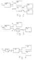
- FIG 1 shows a door intercom system known as Components of a telecommunications system 10 (hereinafter Text briefly referred to as the PBX) with a two-wire interface 11 and two door intercoms 20 and 30 each have a two-wire interface 21 and 31.
- the two-wire interface considered here, it can the Weg two-wire TFE interface act.
- the connection of a door intercom with a two-wire interface to a PBX with one Two-wire interface is detailed in DE-OS 42 36 565 explained.
- a connection module 40 is a new feature introduced and presented with essential components, that the controlled connection of one of the two door intercoms 20, 30 to the PBX 10.
- connection module 40 for connecting several Door intercoms should be designed. It is also conceivable that both the door intercoms 20, 30 and the PABX 10 each have a four-wire interface instead of the Two-wire interfaces 11; 21 and 31.
- connection module 40 there is a switch TFE switch 50 arranged, to which, via the interfaces 21 and 31 the two door intercoms 20, 30 are switched on.
- a current source is connected to this switch 50 60 turned on, which the not with the PABX 10 connected door intercom 20 with a quiescent current provided.
- the door intercoms 20, 30 are also equipped with an election detector 80 connected to that of a door intercom incoming dialing signs are detected and sent to a control device or control logic 70 passes on.
- the control logic 70 is connected to the first switch 50, among other things.
- the connection module 40 also has a connection for an additional door opener 90.
- a door opener changeover 100 as the second changeover switch provided with an AC detector. That detector speaks to an alternating current coming from the PBX 10 on and switches the second changeover switch 100 in such a way that an additionally connected door opener 90 is activated can be.
- the first changeover switch 50 is expediently designed in such a way that that he or she did not connect the or each to the PABX Door intercom connects to a power source, which the door intercoms with a quiescent current feeds. This makes it possible to not even at the PBX connected door intercoms certain To signal system states and those that are not switched on Door intercoms in a standby state hold.
- connection module 40 also has a control logic 70 and a dial detector 80, the controller in response to that detected by the election detector Dialing sign the door intercom that sends this dialing sign via the first switch with the PBX connects.
- connection modules can use two or more connection modules instead of a door station 40 connected in cascade to each other any number of door intercoms to the PBX 10 to be able to switch on.
- the two connection modules are each with a changeover switch 50, a selection detector 80 and a control logic 70 equipped based on the transmitted Recognize the election sign which of the three in FIG. 2 Door intercoms shown with the PABX to be connected.
- connection module 40 a further connection module 40 for Cascading of door intercoms can be connected.
- the connection module is generally designed such that switching on a PBX with a two-wire interface at door intercoms with a two-wire interface enables.
- FIG. 3 shows a further embodiment of a door intercom system shown, the connection of a door intercom 130 with a four-wire interface the PBX 10 with a two-wire interface 120 enables.
- the door intercom 130 is in front Adaptation module 120, e.g. B. a hybrid circuit to which Switch 50 switched on.
- the combination of the connection module 40 and the adaptation module 120 allows an existing door intercom with door intercoms, which have four-wire interfaces, to one after the other to install the installed PBX, which has a two-wire interface owns.
- the door intercom after Fig. 3 can also be modified so that the Connection module 40 several adaptation modules 120 for Switch on door intercoms with a four-wire interface can be connected.
- connection module To also use conventional door intercoms with one Connect the four-wire interface to the connection module To be able to, an adaptation module with a two-wire-four-wire conversion device 140 to the connection module be connected.
- FIG. 4 shows a further embodiment of a door intercom system shown by a PABX with a Four-wire interface runs out.
- a Converter module 140 required that connect the two-wire interface of the connection module 40 with a Four-wire interface of the PBX enables.
- connection module 40 The operation of the connection module 40 is as follows explained with reference to FIG. 1. Every door intercom 20 or 30 activates its own door opener 22, 23.
- the Door intercom 30 is at the interface 31 on the Connection module 40 connected to the PBX 10.
- the signaling is all door intercoms ready to send.
- the switch 50 connects the Door intercom 20 with the power source 60, the one Quiescent current delivers.
- a bell button on the door intercom 20 pressed this signaling is on the election detector 80 is applied.
- the election detector 80 evaluates dials the dialing symbol and sends the result to the control logic 70 on.
- the dialing signs are either an IWV or DTMF dialing signal forwarded to the PBX 10. Subsequently actuates control logic 70 in response to the from Dial detector 60 recognized dial signal switch 50 such that now the door intercom 20 to the telecommunications system 10 is switched on and the door intercom 30 is fed with a quiescent current from the current source 60. This connection remains until one Bell button on the other, not to the PBX 10 switched door intercom 30 is operated.
- the selection detector 80 is connected to the TFE switch 50 always with the non-active Door intercoms connected. After a call ends will always be the last active door intercom from the PBX fed with quiescent current. The last one not active Door intercom is fed by the connection module 40.
- the called party on his telephone who is in conversation with a door intercom 30 is a digit, e.g. B. the number 9, inputs, the evaluation of which is carried out in the telecommunications system 10 is on the two-wire line 11 of the PABX 10 AC voltage applied for a defined time.
- the door opener directly connected to the door intercom 30 33 is activated. It can also, directly to that Connection module 40 another door opener 90 switched on which is always activated, regardless of which door intercom 20; 30 has switched through the TFE switchover 50.
- the door intercom can be connected to the second door 20 may be appropriate. Then the visitor has a bell button Press on the door intercom 20. So far about the Door intercom 30 call is automatic via the switch 50 of the connection module 40 for Door intercom 20 flipped. The called party can in turn typing on his telephone a number, for example the number 9 that the Activate door intercom 20 assigned door opener, to open the second door.
Landscapes
- Engineering & Computer Science (AREA)
- Signal Processing (AREA)
- Interconnected Communication Systems, Intercoms, And Interphones (AREA)
- Passenger Equipment (AREA)
- Walking Sticks, Umbrellas, And Fans (AREA)
- Lock And Its Accessories (AREA)
- Rehabilitation Tools (AREA)
Applications Claiming Priority (2)
| Application Number | Priority Date | Filing Date | Title |
|---|---|---|---|
| DE19704026 | 1997-02-04 | ||
| DE19704026A DE19704026B4 (de) | 1997-02-04 | 1997-02-04 | Türfreisprechanlage |
Publications (3)
| Publication Number | Publication Date |
|---|---|
| EP0856982A2 true EP0856982A2 (fr) | 1998-08-05 |
| EP0856982A3 EP0856982A3 (fr) | 2004-01-21 |
| EP0856982B1 EP0856982B1 (fr) | 2010-02-24 |
Family
ID=7819184
Family Applications (1)
| Application Number | Title | Priority Date | Filing Date |
|---|---|---|---|
| EP97122598A Expired - Lifetime EP0856982B1 (fr) | 1997-02-04 | 1997-12-20 | Interphone |
Country Status (4)
| Country | Link |
|---|---|
| EP (1) | EP0856982B1 (fr) |
| AT (1) | ATE459197T1 (fr) |
| DE (2) | DE19704026B4 (fr) |
| NO (1) | NO980457L (fr) |
Cited By (1)
| Publication number | Priority date | Publication date | Assignee | Title |
|---|---|---|---|---|
| US20110298018A1 (en) * | 2009-12-31 | 2011-12-08 | Institute of Microelectronics, Chinese Academy of Sciences | Transistor and manufacturing method of the same |
Citations (4)
| Publication number | Priority date | Publication date | Assignee | Title |
|---|---|---|---|---|
| DE3023988A1 (de) | 1979-12-19 | 1981-07-02 | Seckelmann GmbH & Co KG, 7800 Freiburg | Gegensprechanlage |
| DE3710091A1 (de) | 1987-03-27 | 1988-10-13 | Siedle & Soehne S | Sprech-, laeut- und oeffneranlage |
| EP0557778A1 (fr) | 1992-02-26 | 1993-09-01 | Siemens Aktiengesellschaft | Système de télécommunication avec un interphone à mains libre |
| DE4236565A1 (de) | 1992-10-29 | 1994-05-05 | Deutsche Bundespost Telekom | Türfreisprechanlage |
Family Cites Families (3)
| Publication number | Priority date | Publication date | Assignee | Title |
|---|---|---|---|---|
| SE467810B (sv) * | 1991-01-29 | 1992-09-14 | Anders Edvard Trell | Saett att signalera/kommunicera inom ett porttelefonsystem samt porttelefonsystem foer kommunikation enligt saettet |
| DE19548744C5 (de) * | 1995-02-28 | 2004-02-05 | TCS TürControlSysteme AG | Signal- und Gegensprechanlage für die Haustechnik |
| DE19524204A1 (de) * | 1995-07-03 | 1997-01-16 | Deutsche Telekom Ag | Telekommunikationsanlage, kombiniert mit einer Torstelle mit Türfreisprecheinrichtung |
-
1997
- 1997-02-04 DE DE19704026A patent/DE19704026B4/de not_active Expired - Fee Related
- 1997-12-20 DE DE59713028T patent/DE59713028D1/de not_active Expired - Lifetime
- 1997-12-20 AT AT97122598T patent/ATE459197T1/de not_active IP Right Cessation
- 1997-12-20 EP EP97122598A patent/EP0856982B1/fr not_active Expired - Lifetime
-
1998
- 1998-02-03 NO NO980457A patent/NO980457L/no unknown
Patent Citations (4)
| Publication number | Priority date | Publication date | Assignee | Title |
|---|---|---|---|---|
| DE3023988A1 (de) | 1979-12-19 | 1981-07-02 | Seckelmann GmbH & Co KG, 7800 Freiburg | Gegensprechanlage |
| DE3710091A1 (de) | 1987-03-27 | 1988-10-13 | Siedle & Soehne S | Sprech-, laeut- und oeffneranlage |
| EP0557778A1 (fr) | 1992-02-26 | 1993-09-01 | Siemens Aktiengesellschaft | Système de télécommunication avec un interphone à mains libre |
| DE4236565A1 (de) | 1992-10-29 | 1994-05-05 | Deutsche Bundespost Telekom | Türfreisprechanlage |
Cited By (1)
| Publication number | Priority date | Publication date | Assignee | Title |
|---|---|---|---|---|
| US20110298018A1 (en) * | 2009-12-31 | 2011-12-08 | Institute of Microelectronics, Chinese Academy of Sciences | Transistor and manufacturing method of the same |
Also Published As
| Publication number | Publication date |
|---|---|
| DE19704026A1 (de) | 1998-08-06 |
| ATE459197T1 (de) | 2010-03-15 |
| DE19704026B4 (de) | 2007-12-27 |
| EP0856982A3 (fr) | 2004-01-21 |
| EP0856982B1 (fr) | 2010-02-24 |
| NO980457D0 (no) | 1998-02-03 |
| DE59713028D1 (de) | 2010-04-08 |
| NO980457L (no) | 1998-08-05 |
Similar Documents
| Publication | Publication Date | Title |
|---|---|---|
| DE2320092C2 (de) | Schaltungsanordnung für Fernmeldeanlagen, in denen Verbindungswege für verschiedene Arten der Nachrichtenübermittlung benutzbar sind Siemens AG, 1000 Berlin und 8000 München | |
| DE4236565C2 (de) | Türfreisprechanlage | |
| DE3737647A1 (de) | Schaltungsanordnung zur umschaltung von verbindungen in einem geraet der nachrichtentechnik | |
| DE19704026B4 (de) | Türfreisprechanlage | |
| EP0148406B1 (fr) | Dispositif téléphonique avec un appareil d'abonné pour solliciter des informations, introduire des réponses et engendrer des messages de nature numérique codée | |
| DE2134125A1 (de) | Fernbedienbare Telephonwähleinriehtung | |
| DE3440307A1 (de) | Schaltungsanordnung fuer zweieranschluesse bei fernmelde-, insbesondere fernsprechvermittlungsanlagen | |
| DE19534539C1 (de) | Türfreisprechanlage | |
| DE3130410A1 (de) | Analog-/digital-fernmeldesystem | |
| DE9205166U1 (de) | Türsprech- und Steueranlage | |
| DE19534537C1 (de) | Türfreisprechanlage | |
| DE3920721A1 (de) | Sprechanlage mit sprechstelle mit datenanzeige | |
| EP0198176B1 (fr) | Méthode pour informer un abonné téléphonique des états de connexion existants de son raccordement | |
| DE4205814A1 (de) | Isdn-fernsprechnebenstellenanlage | |
| DE4204517C2 (de) | Mikroprozessorgesteuerte Telekommunikationseinrichtung | |
| EP0901268A2 (fr) | Dispositif avec un interphone d'immeuble et une pluralité d'interphones d'appartement interconnecté par un bus à deux fils | |
| DE3502987C2 (fr) | ||
| DE3216785C2 (de) | Verfahren zur Abschaltung von Wahlumsetzeinrichtungen in Fernmelde-, insbesondere Fernsprechanlagen | |
| DE3146398C2 (de) | Schaltungsanordnung für ein im Selektivbetrieb arbeitendes Gesellschaftsleitungstelefonnetz | |
| EP0570749A2 (fr) | Circuit de transmission de signaux de télécommunication | |
| DE2341971B2 (de) | Einrichtung zur nachrichtenuebermittlung zwischen einer personenrufanlage und einer drahtgebundenen sprechanlage | |
| DE3145024C1 (de) | Verfahren für eine mikroprozessorgesteuerte Fernsprechnebenstellenanlage, insbesondere Reihenanlage mit Außenstationen | |
| DE2828583B2 (de) | Teilnehmerstation | |
| DE3526708A1 (de) | Schaltungsanordnung zur rbertragung von wahlinformationen zwischen nachrichtenvermittlungsanlagen innerhalb eines kommunikationsnetzes | |
| DE2102934C3 (de) | Schaltungsanordnung zur Verbindung von Teilnehmerstellen mit Fernsehtelefonbetrieb |
Legal Events
| Date | Code | Title | Description |
|---|---|---|---|
| PUAI | Public reference made under article 153(3) epc to a published international application that has entered the european phase |
Free format text: ORIGINAL CODE: 0009012 |
|
| AK | Designated contracting states |
Kind code of ref document: A2 Designated state(s): AT BE CH DE DK ES FI FR GB GR IE IT LI LU MC NL PT SE |
|
| AX | Request for extension of the european patent |
Free format text: AL;LT;LV;MK;RO;SI |
|
| PUAL | Search report despatched |
Free format text: ORIGINAL CODE: 0009013 |
|
| AK | Designated contracting states |
Kind code of ref document: A3 Designated state(s): AT BE CH DE DK ES FI FR GB GR IE IT LI LU MC NL PT SE |
|
| AX | Request for extension of the european patent |
Extension state: AL LT LV MK RO SI |
|
| RIC1 | Information provided on ipc code assigned before grant |
Ipc: 7H 04M 9/00 B Ipc: 7H 04M 11/02 A |
|
| 17P | Request for examination filed |
Effective date: 20040721 |
|
| 17Q | First examination report despatched |
Effective date: 20040817 |
|
| AKX | Designation fees paid |
Designated state(s): AT BE DE DK ES FI FR GB GR IE LU NL PT SE |
|
| GRAP | Despatch of communication of intention to grant a patent |
Free format text: ORIGINAL CODE: EPIDOSNIGR1 |
|
| GRAS | Grant fee paid |
Free format text: ORIGINAL CODE: EPIDOSNIGR3 |
|
| GRAA | (expected) grant |
Free format text: ORIGINAL CODE: 0009210 |
|
| AK | Designated contracting states |
Kind code of ref document: B1 Designated state(s): AT BE DE DK ES FI FR GB GR IE LU NL PT SE |
|
| REG | Reference to a national code |
Ref country code: GB Ref legal event code: FG4D Free format text: NOT ENGLISH |
|
| REG | Reference to a national code |
Ref country code: IE Ref legal event code: FG4D Free format text: LANGUAGE OF EP DOCUMENT: GERMAN |
|
| REF | Corresponds to: |
Ref document number: 59713028 Country of ref document: DE Date of ref document: 20100408 Kind code of ref document: P |
|
| REG | Reference to a national code |
Ref country code: NL Ref legal event code: VDEP Effective date: 20100224 |
|
| PG25 | Lapsed in a contracting state [announced via postgrant information from national office to epo] |
Ref country code: PT Free format text: LAPSE BECAUSE OF FAILURE TO SUBMIT A TRANSLATION OF THE DESCRIPTION OR TO PAY THE FEE WITHIN THE PRESCRIBED TIME-LIMIT Effective date: 20100624 |
|
| PG25 | Lapsed in a contracting state [announced via postgrant information from national office to epo] |
Ref country code: FI Free format text: LAPSE BECAUSE OF FAILURE TO SUBMIT A TRANSLATION OF THE DESCRIPTION OR TO PAY THE FEE WITHIN THE PRESCRIBED TIME-LIMIT Effective date: 20100224 |
|
| REG | Reference to a national code |
Ref country code: IE Ref legal event code: FD4D |
|
| PG25 | Lapsed in a contracting state [announced via postgrant information from national office to epo] |
Ref country code: SE Free format text: LAPSE BECAUSE OF FAILURE TO SUBMIT A TRANSLATION OF THE DESCRIPTION OR TO PAY THE FEE WITHIN THE PRESCRIBED TIME-LIMIT Effective date: 20100224 Ref country code: NL Free format text: LAPSE BECAUSE OF FAILURE TO SUBMIT A TRANSLATION OF THE DESCRIPTION OR TO PAY THE FEE WITHIN THE PRESCRIBED TIME-LIMIT Effective date: 20100224 Ref country code: IE Free format text: LAPSE BECAUSE OF FAILURE TO SUBMIT A TRANSLATION OF THE DESCRIPTION OR TO PAY THE FEE WITHIN THE PRESCRIBED TIME-LIMIT Effective date: 20100224 Ref country code: GR Free format text: LAPSE BECAUSE OF FAILURE TO SUBMIT A TRANSLATION OF THE DESCRIPTION OR TO PAY THE FEE WITHIN THE PRESCRIBED TIME-LIMIT Effective date: 20100525 Ref country code: ES Free format text: LAPSE BECAUSE OF FAILURE TO SUBMIT A TRANSLATION OF THE DESCRIPTION OR TO PAY THE FEE WITHIN THE PRESCRIBED TIME-LIMIT Effective date: 20100604 |
|
| PLBE | No opposition filed within time limit |
Free format text: ORIGINAL CODE: 0009261 |
|
| STAA | Information on the status of an ep patent application or granted ep patent |
Free format text: STATUS: NO OPPOSITION FILED WITHIN TIME LIMIT |
|
| PG25 | Lapsed in a contracting state [announced via postgrant information from national office to epo] |
Ref country code: DK Free format text: LAPSE BECAUSE OF FAILURE TO SUBMIT A TRANSLATION OF THE DESCRIPTION OR TO PAY THE FEE WITHIN THE PRESCRIBED TIME-LIMIT Effective date: 20100224 |
|
| 26N | No opposition filed |
Effective date: 20101125 |
|
| BERE | Be: lapsed |
Owner name: DEUTSCHE TELEKOM A.G. Effective date: 20101231 |
|
| PG25 | Lapsed in a contracting state [announced via postgrant information from national office to epo] |
Ref country code: BE Free format text: LAPSE BECAUSE OF NON-PAYMENT OF DUE FEES Effective date: 20101231 |
|
| PG25 | Lapsed in a contracting state [announced via postgrant information from national office to epo] |
Ref country code: AT Free format text: LAPSE BECAUSE OF NON-PAYMENT OF DUE FEES Effective date: 20101220 |
|
| REG | Reference to a national code |
Ref country code: AT Ref legal event code: MM01 Ref document number: 459197 Country of ref document: AT Kind code of ref document: T Effective date: 20101220 |
|
| PG25 | Lapsed in a contracting state [announced via postgrant information from national office to epo] |
Ref country code: LU Free format text: LAPSE BECAUSE OF NON-PAYMENT OF DUE FEES Effective date: 20101220 |
|
| REG | Reference to a national code |
Ref country code: FR Ref legal event code: PLFP Year of fee payment: 19 |
|
| PGFP | Annual fee paid to national office [announced via postgrant information from national office to epo] |
Ref country code: GB Payment date: 20151221 Year of fee payment: 19 |
|
| PGFP | Annual fee paid to national office [announced via postgrant information from national office to epo] |
Ref country code: FR Payment date: 20151218 Year of fee payment: 19 |
|
| PGFP | Annual fee paid to national office [announced via postgrant information from national office to epo] |
Ref country code: DE Payment date: 20151217 Year of fee payment: 19 |
|
| REG | Reference to a national code |
Ref country code: DE Ref legal event code: R119 Ref document number: 59713028 Country of ref document: DE |
|
| GBPC | Gb: european patent ceased through non-payment of renewal fee |
Effective date: 20161220 |
|
| REG | Reference to a national code |
Ref country code: FR Ref legal event code: ST Effective date: 20170831 |
|
| PG25 | Lapsed in a contracting state [announced via postgrant information from national office to epo] |
Ref country code: FR Free format text: LAPSE BECAUSE OF NON-PAYMENT OF DUE FEES Effective date: 20170102 |
|
| PG25 | Lapsed in a contracting state [announced via postgrant information from national office to epo] |
Ref country code: GB Free format text: LAPSE BECAUSE OF NON-PAYMENT OF DUE FEES Effective date: 20161220 Ref country code: DE Free format text: LAPSE BECAUSE OF NON-PAYMENT OF DUE FEES Effective date: 20170701 |