EP0855703A2 - Verfahren zur Laminierung von Plattensubstraten - Google Patents
Verfahren zur Laminierung von Plattensubstraten Download PDFInfo
- Publication number
- EP0855703A2 EP0855703A2 EP98101387A EP98101387A EP0855703A2 EP 0855703 A2 EP0855703 A2 EP 0855703A2 EP 98101387 A EP98101387 A EP 98101387A EP 98101387 A EP98101387 A EP 98101387A EP 0855703 A2 EP0855703 A2 EP 0855703A2
- Authority
- EP
- European Patent Office
- Prior art keywords
- disc
- shaped substrate
- sheet body
- adhesive
- adhesive agent
- Prior art date
- Legal status (The legal status is an assumption and is not a legal conclusion. Google has not performed a legal analysis and makes no representation as to the accuracy of the status listed.)
- Granted
Links
Images


Classifications
-
- B—PERFORMING OPERATIONS; TRANSPORTING
- B32—LAYERED PRODUCTS
- B32B—LAYERED PRODUCTS, i.e. PRODUCTS BUILT-UP OF STRATA OF FLAT OR NON-FLAT, e.g. CELLULAR OR HONEYCOMB, FORM
- B32B38/00—Ancillary operations in connection with laminating processes
- B32B38/10—Removing layers, or parts of layers, mechanically or chemically
-
- B—PERFORMING OPERATIONS; TRANSPORTING
- B29—WORKING OF PLASTICS; WORKING OF SUBSTANCES IN A PLASTIC STATE IN GENERAL
- B29C—SHAPING OR JOINING OF PLASTICS; SHAPING OF MATERIAL IN A PLASTIC STATE, NOT OTHERWISE PROVIDED FOR; AFTER-TREATMENT OF THE SHAPED PRODUCTS, e.g. REPAIRING
- B29C65/00—Joining or sealing of preformed parts, e.g. welding of plastics materials; Apparatus therefor
- B29C65/48—Joining or sealing of preformed parts, e.g. welding of plastics materials; Apparatus therefor using adhesives, i.e. using supplementary joining material; solvent bonding
-
- B—PERFORMING OPERATIONS; TRANSPORTING
- B29—WORKING OF PLASTICS; WORKING OF SUBSTANCES IN A PLASTIC STATE IN GENERAL
- B29C—SHAPING OR JOINING OF PLASTICS; SHAPING OF MATERIAL IN A PLASTIC STATE, NOT OTHERWISE PROVIDED FOR; AFTER-TREATMENT OF THE SHAPED PRODUCTS, e.g. REPAIRING
- B29C66/00—General aspects of processes or apparatus for joining preformed parts
- B29C66/01—General aspects dealing with the joint area or with the area to be joined
- B29C66/05—Particular design of joint configurations
- B29C66/10—Particular design of joint configurations particular design of the joint cross-sections
- B29C66/11—Joint cross-sections comprising a single joint-segment, i.e. one of the parts to be joined comprising a single joint-segment in the joint cross-section
- B29C66/112—Single lapped joints
- B29C66/1122—Single lap to lap joints, i.e. overlap joints
-
- B—PERFORMING OPERATIONS; TRANSPORTING
- B29—WORKING OF PLASTICS; WORKING OF SUBSTANCES IN A PLASTIC STATE IN GENERAL
- B29C—SHAPING OR JOINING OF PLASTICS; SHAPING OF MATERIAL IN A PLASTIC STATE, NOT OTHERWISE PROVIDED FOR; AFTER-TREATMENT OF THE SHAPED PRODUCTS, e.g. REPAIRING
- B29C66/00—General aspects of processes or apparatus for joining preformed parts
- B29C66/01—General aspects dealing with the joint area or with the area to be joined
- B29C66/345—Progressively making the joint, e.g. starting from the middle
-
- B—PERFORMING OPERATIONS; TRANSPORTING
- B29—WORKING OF PLASTICS; WORKING OF SUBSTANCES IN A PLASTIC STATE IN GENERAL
- B29C—SHAPING OR JOINING OF PLASTICS; SHAPING OF MATERIAL IN A PLASTIC STATE, NOT OTHERWISE PROVIDED FOR; AFTER-TREATMENT OF THE SHAPED PRODUCTS, e.g. REPAIRING
- B29C66/00—General aspects of processes or apparatus for joining preformed parts
- B29C66/40—General aspects of joining substantially flat articles, e.g. plates, sheets or web-like materials; Making flat seams in tubular or hollow articles; Joining single elements to substantially flat surfaces
- B29C66/41—Joining substantially flat articles ; Making flat seams in tubular or hollow articles
- B29C66/45—Joining of substantially the whole surface of the articles
- B29C66/452—Joining of substantially the whole surface of the articles the article having a disc form, e.g. making CDs or DVDs
-
- B—PERFORMING OPERATIONS; TRANSPORTING
- B29—WORKING OF PLASTICS; WORKING OF SUBSTANCES IN A PLASTIC STATE IN GENERAL
- B29C—SHAPING OR JOINING OF PLASTICS; SHAPING OF MATERIAL IN A PLASTIC STATE, NOT OTHERWISE PROVIDED FOR; AFTER-TREATMENT OF THE SHAPED PRODUCTS, e.g. REPAIRING
- B29C66/00—General aspects of processes or apparatus for joining preformed parts
- B29C66/80—General aspects of machine operations or constructions and parts thereof
- B29C66/81—General aspects of the pressing elements, i.e. the elements applying pressure on the parts to be joined in the area to be joined, e.g. the welding jaws or clamps
- B29C66/814—General aspects of the pressing elements, i.e. the elements applying pressure on the parts to be joined in the area to be joined, e.g. the welding jaws or clamps characterised by the design of the pressing elements, e.g. of the welding jaws or clamps
- B29C66/8145—General aspects of the pressing elements, i.e. the elements applying pressure on the parts to be joined in the area to be joined, e.g. the welding jaws or clamps characterised by the design of the pressing elements, e.g. of the welding jaws or clamps characterised by the constructional aspects of the pressing elements, e.g. of the welding jaws or clamps
- B29C66/81455—General aspects of the pressing elements, i.e. the elements applying pressure on the parts to be joined in the area to be joined, e.g. the welding jaws or clamps characterised by the design of the pressing elements, e.g. of the welding jaws or clamps characterised by the constructional aspects of the pressing elements, e.g. of the welding jaws or clamps being a fluid inflatable bag or bladder, a diaphragm or a vacuum bag for applying isostatic pressure
-
- B—PERFORMING OPERATIONS; TRANSPORTING
- B29—WORKING OF PLASTICS; WORKING OF SUBSTANCES IN A PLASTIC STATE IN GENERAL
- B29C—SHAPING OR JOINING OF PLASTICS; SHAPING OF MATERIAL IN A PLASTIC STATE, NOT OTHERWISE PROVIDED FOR; AFTER-TREATMENT OF THE SHAPED PRODUCTS, e.g. REPAIRING
- B29C66/00—General aspects of processes or apparatus for joining preformed parts
- B29C66/80—General aspects of machine operations or constructions and parts thereof
- B29C66/83—General aspects of machine operations or constructions and parts thereof characterised by the movement of the joining or pressing tools
- B29C66/832—Reciprocating joining or pressing tools
- B29C66/8322—Joining or pressing tools reciprocating along one axis
-
- B—PERFORMING OPERATIONS; TRANSPORTING
- B32—LAYERED PRODUCTS
- B32B—LAYERED PRODUCTS, i.e. PRODUCTS BUILT-UP OF STRATA OF FLAT OR NON-FLAT, e.g. CELLULAR OR HONEYCOMB, FORM
- B32B37/00—Methods or apparatus for laminating, e.g. by curing or by ultrasonic bonding
- B32B37/0007—Methods or apparatus for laminating, e.g. by curing or by ultrasonic bonding involving treatment or provisions in order to avoid deformation or air inclusion, e.g. to improve surface quality
-
- B—PERFORMING OPERATIONS; TRANSPORTING
- B32—LAYERED PRODUCTS
- B32B—LAYERED PRODUCTS, i.e. PRODUCTS BUILT-UP OF STRATA OF FLAT OR NON-FLAT, e.g. CELLULAR OR HONEYCOMB, FORM
- B32B37/00—Methods or apparatus for laminating, e.g. by curing or by ultrasonic bonding
- B32B37/10—Methods or apparatus for laminating, e.g. by curing or by ultrasonic bonding characterised by the pressing technique, e.g. using action of vacuum or fluid pressure
-
- G—PHYSICS
- G11—INFORMATION STORAGE
- G11B—INFORMATION STORAGE BASED ON RELATIVE MOVEMENT BETWEEN RECORD CARRIER AND TRANSDUCER
- G11B7/00—Recording or reproducing by optical means, e.g. recording using a thermal beam of optical radiation by modifying optical properties or the physical structure, reproducing using an optical beam at lower power by sensing optical properties; Record carriers therefor
- G11B7/24—Record carriers characterised by shape, structure or physical properties, or by the selection of the material
- G11B7/26—Apparatus or processes specially adapted for the manufacture of record carriers
-
- B—PERFORMING OPERATIONS; TRANSPORTING
- B29—WORKING OF PLASTICS; WORKING OF SUBSTANCES IN A PLASTIC STATE IN GENERAL
- B29C—SHAPING OR JOINING OF PLASTICS; SHAPING OF MATERIAL IN A PLASTIC STATE, NOT OTHERWISE PROVIDED FOR; AFTER-TREATMENT OF THE SHAPED PRODUCTS, e.g. REPAIRING
- B29C65/00—Joining or sealing of preformed parts, e.g. welding of plastics materials; Apparatus therefor
- B29C65/48—Joining or sealing of preformed parts, e.g. welding of plastics materials; Apparatus therefor using adhesives, i.e. using supplementary joining material; solvent bonding
- B29C65/4805—Joining or sealing of preformed parts, e.g. welding of plastics materials; Apparatus therefor using adhesives, i.e. using supplementary joining material; solvent bonding characterised by the type of adhesives
- B29C65/483—Reactive adhesives, e.g. chemically curing adhesives
- B29C65/4845—Radiation curing adhesives, e.g. UV light curing adhesives
-
- B—PERFORMING OPERATIONS; TRANSPORTING
- B29—WORKING OF PLASTICS; WORKING OF SUBSTANCES IN A PLASTIC STATE IN GENERAL
- B29L—INDEXING SCHEME ASSOCIATED WITH SUBCLASS B29C, RELATING TO PARTICULAR ARTICLES
- B29L2017/00—Carriers for sound or information
- B29L2017/001—Carriers of records containing fine grooves or impressions, e.g. disc records for needle playback, cylinder records
- B29L2017/003—Records or discs
- B29L2017/005—CD''s, DVD''s
-
- B—PERFORMING OPERATIONS; TRANSPORTING
- B32—LAYERED PRODUCTS
- B32B—LAYERED PRODUCTS, i.e. PRODUCTS BUILT-UP OF STRATA OF FLAT OR NON-FLAT, e.g. CELLULAR OR HONEYCOMB, FORM
- B32B2429/00—Carriers for sound or information
- B32B2429/02—Records or discs
-
- B—PERFORMING OPERATIONS; TRANSPORTING
- B32—LAYERED PRODUCTS
- B32B—LAYERED PRODUCTS, i.e. PRODUCTS BUILT-UP OF STRATA OF FLAT OR NON-FLAT, e.g. CELLULAR OR HONEYCOMB, FORM
- B32B38/00—Ancillary operations in connection with laminating processes
- B32B38/16—Drying; Softening; Cleaning
- B32B38/162—Cleaning
-
- Y—GENERAL TAGGING OF NEW TECHNOLOGICAL DEVELOPMENTS; GENERAL TAGGING OF CROSS-SECTIONAL TECHNOLOGIES SPANNING OVER SEVERAL SECTIONS OF THE IPC; TECHNICAL SUBJECTS COVERED BY FORMER USPC CROSS-REFERENCE ART COLLECTIONS [XRACs] AND DIGESTS
- Y10—TECHNICAL SUBJECTS COVERED BY FORMER USPC
- Y10T—TECHNICAL SUBJECTS COVERED BY FORMER US CLASSIFICATION
- Y10T156/00—Adhesive bonding and miscellaneous chemical manufacture
- Y10T156/10—Methods of surface bonding and/or assembly therefor
- Y10T156/1052—Methods of surface bonding and/or assembly therefor with cutting, punching, tearing or severing
-
- Y—GENERAL TAGGING OF NEW TECHNOLOGICAL DEVELOPMENTS; GENERAL TAGGING OF CROSS-SECTIONAL TECHNOLOGIES SPANNING OVER SEVERAL SECTIONS OF THE IPC; TECHNICAL SUBJECTS COVERED BY FORMER USPC CROSS-REFERENCE ART COLLECTIONS [XRACs] AND DIGESTS
- Y10—TECHNICAL SUBJECTS COVERED BY FORMER USPC
- Y10T—TECHNICAL SUBJECTS COVERED BY FORMER US CLASSIFICATION
- Y10T428/00—Stock material or miscellaneous articles
- Y10T428/14—Layer or component removable to expose adhesive
-
- Y—GENERAL TAGGING OF NEW TECHNOLOGICAL DEVELOPMENTS; GENERAL TAGGING OF CROSS-SECTIONAL TECHNOLOGIES SPANNING OVER SEVERAL SECTIONS OF THE IPC; TECHNICAL SUBJECTS COVERED BY FORMER USPC CROSS-REFERENCE ART COLLECTIONS [XRACs] AND DIGESTS
- Y10—TECHNICAL SUBJECTS COVERED BY FORMER USPC
- Y10T—TECHNICAL SUBJECTS COVERED BY FORMER US CLASSIFICATION
- Y10T428/00—Stock material or miscellaneous articles
- Y10T428/21—Circular sheet or circular blank
Definitions
- the present invention relates to a method of laminating disc-shaped substrates, particularly to a method of integrally laminating two substrates using an adhesive sheet.
- Computers, especially personal computers are remarkably popularlized recently, and storage media to be used thereby, particularly capacity of a storage disc has been high dense and kinds of the storage media are increased.
- a magnetic disc e.g., CD-ROM
- an optical magnetic disc e.g., MO
- the demand of the optical disc as the storage disc is increased recently.
- a disc-shaped substrate that is a single plate constituting the DVD is required to have a thickness of 0.6 mm and an outer diameter of 120 mm and an inner diameter of its central hole of 15 mm. Since such a thin disc-shaped substrate formed of a single plate is low in mechanical strength and is easily deformable, and in view of storage capacity, the disc-shaped substrates each having the same thickness (0.6 mm) are bonded to each other to form an integrated substrate in a practical use thereof.
- Such a high dense storage disc including a DVD is generally used as a laminated structure as set forth above, but not used as a single plate. In such a case, it is needless to say that both the upper and lower disc-shaped substrates are needed to be bonded to each other.
- the storage disc is manufactured by the aforementioned steps, namely, the two disc-shaped substrates D1 and D2 are bonded to each other to form a single integrated plate.
- the thickness of the adhesive layer is not at all uniform. Still further, there is another problem that the number of manufacturing steps increases to increase the manufacturing cost because of the necessity of the step of irradiating adhesive agent with UV to cure the adhesive agent.
- the adhesive agent is bonded to one of two disc-shaped substrates to be bonded, thereafter the one disc-shaped substrate is overlaid on the other disc-shaped substrate.
- An adhesive agent is generally used in a state where it is bonded to a sheeting, i.e. adhesive sheet body forming a base member, wherein a plurality of adhesive sheets to which the adhesive agent is bonded are bonded to the adhesive sheet body S. Accordingly, it is very ineffective to peel off the adhesive agent on the adhesive sheet one by one manually to bond or transfer it to the lower disc-shaped substrate when two disc-shaped substrates are bonded to each other. Further, bonding operation of an adhesive agent need be automated to incorporate the bonding operation of the adhesive agent to the disc-shaped substrates into the laminating lines of the disc-shaped substrates so as to produce a series of laminating lines which are sequentially controlled as a whole. That is, it is inevitable to automatically bond the adhesive agent to the disc-shaped substrate to produce continuous laminating lines.
- the present invention has been made to solve the aforementioned problems. That is, it is an object of the invention to provide a method of laminating disc-shaped substrates capable of automatically bonding an adhesive agent to the disc-shaped substrates very effectively and continuously.
- release paper is peeled off from an adhesive agent bonded to an adhesive sheet body and the exposed adhesive agent is bonded to the lower disc-shaped substrate so as to sequentially boding the adhesive agent to the lower disc-shaped substrate D1, and thereafter has completed the invention.
- a method of laminating disc-shaped substrates comprises preparing an adhesive sheeting (hereinafter referred to as adhesive sheet body) S comprising a plurality of adhesive sheets (hereinafter referred to as adhesive agents) S2 each covered with a release paper S3 and bonded to the adhesive sheet body S, peeling off the release paper S3 from the adhesive agent S2, pressing the exposed adhesive agent S2 from which the release paper S3 is peeled off to a surface of a lower disc-shaped substrate D1 so as to bond or transfer the adhesive agent S2 provided on the adhesive sheet body, and also peeling off the adhesive sheet body from the adhesive agent S2 bonded to the upper surface of the lower disc-shaped substrate D1 placing an upper disc-shaped substrate D2 to the lower disc-shaped substrate D1 pressing the upper disc-shaped substrate D2 against the lower disc-shaped substrate D1, thereby bonding two lower disc-shaped substrate D1 and upper disc-shaped substrate D2.
- adhesive sheet body comprising a plurality of adhesive sheets (hereinafter referred to as adhesive agents) S2 each covered with
- a method of laminating disc-shaped substrates according to a second aspect of the invention comprises the following steps 1 to 7.
- the method of laminating disc-shaped substrates according to a third aspect of the invention further includes a step of collecting the release paper S3 in the second aspect of the invention.
- the method of laminating disc-shaped substrates according to a fourth aspect of the invention is characterized in that the step of collecting the release paper S3 in the third aspect of the invention is performed using an adhesive tape having an adhesion force relative to the release paper S3 which is greater than that of the adhesive agent S2 relative to the release paper S3.
- the method of laminating disc-shaped substrates according to a fifth aspect of the invention is characterized in that the step of (4) in the second aspect of the invention comprises pressing the adhesive sheet body S against the lower disc-shaped substrate D1 from a central portion to an outer portion thereof to enlarge a contact portion so as to bond the adhesive agent S2 to the lower disc-shaped substrate D1.
- the method of laminating disc-shaped substrates according to a sixth aspect of the invention characterized in that the step of (5) in the second aspect of the invention comprises peeling off the adhesive agent S2 from the adhesive sheet body S, namely, carrier S1 by a peeling member which traverses between the adhesive sheet body S and the lower disc-shaped substrate D1 placed on the holding table 2.
- the method of laminating disc-shaped substrates according to an seventh aspect of the invention characterized in that the step of (5) in the second aspect of the invention comprises peeling off the adhesive sheet body S from the adhesive agent S2 in a state where the adhesive sheet body S is relaxed.
- the method of laminating disc-shaped substrates according to an eighth aspect of the invention characterized in that the step of (5) in the second aspect of the invention comprises tightening the adhesive sheet body S immediately after the adhesive sheet body S is peeled off from the adhesive agent S2.
- the method of laminating disc-shaped substrates according to a ninth aspect of the invention characterized in that the step of (7) in the second aspect of the invention comprises pressing the upper disc-shaped substrate D2 against the lower disc-shaped substrate D1 from a central portion to an outer portion thereof to enlarge a contact portion so as to bond the adhesive agent S2 to the lower disc-shaped substrate D1.
- the adhesive agent can be continuously and automatically bonded to the lower disc-shaped substrate thereby making it possible to effectively bond the disc-shaped substrates.
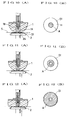
- FIG. 1 A method of laminating disc-shaped substrates according to the present invention will be now described with reference to Figs. 1 to 9 showing the steps for bonding an adhesive agent S2 to a lower disc-shaped substrate D1.
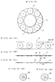
- the adhesive sheet body S comprises a carrier S1 formed of a long base, adhesive agent S2 which is bonded to the carrier S1 and formed of synthetic resin tape such as thin polyethylene and release paper S3 temporarily bonded to the surface of the adhesive agent S2 (See Fig. 1).
- Fig. 14(A) shows a front view of the adhesive sheet body S
- Fig. 14(B) is a side view of the adhesive sheet body S
- Fig. 14(C) is a side view showing a state where the release paper S3 is peeled off from the adhesive agent S2.
- the adhesive agent S2 forms a fixed medium for integrally laminating the disc-shaped substrates D1 and D2 described later, and comprises a plurality of LP (long-playing record)-shaped sheets (See Fig. 15(A)) each bonded to the surface of the carrier S1 at regular intervals.
- a pressure sensitive adhesive agent as the adhesive agent S2 such as rubber-based adhesive agent, acrylic adhesive agent, silicon adhesive agent, vinyl adhesive agent and polyethylene adhesive agent. It is possible to select the optimum thickness of the adhesive agent S2 depending on the kind of storage disc to be designed.
- the release paper S3 is temporarily bonded to the adhesive agent S2 to cover the adhesive agent S2 and has the same shape as that of the adhesive agent S2 (See Fig. 15(B)).
- the adhesive sheet body S has many holes P each penetrating the carrier S1, adhesive agent S2 and the release paper S3 at the same time when it is manufactured. Each hole P is utilized for positioning the adhesive agent S2 relative to the holding table 2.
- the release paper S3 is peeled off from the adhesive agent S2 bonded on the pressing body 1 when the adhesive sheet body S is supplied between a pressing body 1 and the holding table 2.
- the adhesive agent S2 is bonded to the lower disc-shaped substrate D1 in the following manner.
- Fig. 1 shows a method of bonding the adhesive agent S2 wherein the adhesive sheet body S is released and unwound from a first supply roller 7. Bonded matter such as dust is removed from the adhesive sheet body S by a cleaning roller 6 after the adhesive sheet body S unwound from the first supply roller 7. Thereafter, the adhesive sheet body S passes through a stop roller 5, then it is supplied to a first tension roller 4A and a first expansion roller 3A. The stop roller 5 presses the adhesive sheet body S against a lower table to hold the adhesive sheet body S at the upper and lower portions thereof, and it can stop the movement of the adhesive sheet body S when needed.
- the adhesive sheet body S which passed through the first expansion roller 3A is supplied between the holding table 2 and the pressing body 1.
- the adhesive sheet body S receives a pressing force between the holding table 2 and pressing body 1 so as to bond the adhesive agent S2 to the surface of the lower disc-shaped substrate D1 which is placed on the holding table 2, described later.
- the adhesive sheet body S passes through a second expansion roller 3B and second tension roller 4B, then it is supplied to a feed roller 10.
- the feed roller 10 is positively driven to cooperate with the stop roller 5 so as to move the adhesive sheet body S when necessary.
- the adhesive sheet body S fed from the feed roller 10 is wound by a second winding roller 12 through a hanging roller 11.
- the hanging roller 11 is hung from the adhesive sheet body S and it lowers when the adhesive sheet body S is fed from the feed roller 10.
- a detector 11a detects the lowering of the hanging roller 11, and issues a detection signal.
- the second winding roller 12 is rotated upon detection of the detection signal from the detector 11a so as to wind the adhesive sheet body S.
- the adhesive agent S2 is bonded to the lower disc-shaped substrate D1.
- the adhesive sheet body S is supplied between the holding table 2 and pressing body 1 in a state where the release paper S3 is removed from the adhesive agent S2, namely in a state where the adhesive face of the adhesive agent S2 is exposed.
- An adhesive tape L is used as means for removing or peeling off the release paper S3 from the adhesive agent S2 bonded on the adhesive sheet body S. That is, as illustrated in the drawings, the adhesive sheet body S unwound from the first supply roller 7 has the adhesive agent S2 bonded on the carrier S1, and the release paper S3 is bonded to the adhesive face of the adhesive agent S2.
- the adhesive tape L which is supplied from a second supply roller 8 has an adhesive face at the back side, and the adhesive face of the adhesive tape L opposes the release paper S3 of the adhesive sheet body S and they contact each other at a guide roller 71.
- the adhesive tape L and the adhesive sheet body S respectively pass through the guide roller 71, cleaning roller 6, stop roller 5, first tension roller 4A and first expansion roller 3A and bonded to each other.
- the adhesive face of the adhesive tape L is bonded to the release paper S3 of the adhesive sheet body S.
- the release paper S3 is peeled off from the adhesive agent S2 of the adhesive sheet body S owing to adhesion of the adhesive tape L.
- the adhesive tape L received the release paper S3, it is wound by a first winding roller 9 so that the release paper S3 is collected.
- the reason why the release paper S3 is collected when it is separated from the adhesive sheet body S using the adhesive tape L is caused by the difference of adhesion, namely, the adhesion of the adhesive tape L relative to the release paper S3 is larger than that of the adhesive agent S2 relative to the release paper S3. That is, the adhesive tape L is needed to have adhesion relative to the release paper S3 which is greater than the peeling strength of the release paper S3 relative to the adhesive agent S2.
- the adhesive sheet body S which passes through the first tension roller 4A is supported between the first and second expansion rollers 3A and 3B which are respectively disposed at the front and rear holding table 2 and pressing body 1 in a state where the adhesive face of the LP-shaped adhesive agent S2 is exposed.
- a given tension is given to the adhesive sheet body S, which is supported by the first and second expansion rollers 3A and 3B, by the first and second tension rollers 4A and 4B respectively disposed adjacent to the first and second expansion rollers 3A and 3B, and hence the adhesive sheet body S is held in the tightening state (initial state).
- Fig. 1 shows the initial pressing state where the adhesive sheet body S is positioned substantially in the middle between the pressing body 1 and holding table 2. Thereafter, the stop roller 5 lowers so that the adhesive sheet body S is held in a stopping position.
- the distance between the first and second expansion rollers 3A and 3B is reduced so that the adhesive sheet body S is held in a given relaxing state.
- the reason why the adhesive sheet body S is held in the relaxing state is to secure the accurate positioning of the adhesive agent S2 by the pressing body 1.
- the pressing body 1 lowers so that the positioning of the adhesive sheet body S, namely, the adhesive agent S2 relative to the lower disc-shaped substrate D1 is performed by a projecting core 1A provided at the center of the pressing body 1.
- the tip end of the projecting core 1A projecting from the tip end of the pressing body 1 is inserted into the hole P of the adhesive sheet body S.
- the adhesive sheet body S per se is not tightened but relaxed, there occurs a slight degree of freedom in the motion of the adhesive sheet body S so that the projecting core 1A is easily inserted into the hole P of the adhesive sheet body S. Accordingly, the adhesive agent S2 of the adhesive sheet body S is accurately positioned immediately over the lower disc-shaped substrate D1.
- the holding table 2 moves upward as shown in Fig. 4.
- the holding table 2 presses gradually the lower surface of the flexible and hemispherical pressing body 1 from the bottom to the top so as to deform the lower half part of the pressing body 1 in a flat manner.
- the adhesive sheet body S positioned between the holding table 2 and pressing body 1 is pressed against the pressing body 1 by this operation.
- the pressing body 1 gradually presses the adhesive sheet body S from the central portion to the outer portion (radially) so that the contact portion therebetween expands.
- the adhesive agent S2 bonded to the lower surface of the adhesive sheet body S is bonded or transferred to the surface of the lower disc-shaped substrate D1 in a state where air bubbles, etc., do not mix therein or no wrinkling is generated therein.
- the pressing body 1 is a hemispherical and flexible member as set forth above, it can be easily deformed when it is pressed.
- the tip end of the projecting core 1A disposed at a central hole 1B of the pressing body 1 slightly projects from the tip end of the pressing body 1 and hence it can be recessed when the pressing body 1 is pressed.
- the pressing state of the pressing body 1 relative to the holding table 2 when the holding table 2 moves upward relative to the pressing body 1 to press the pressing body 1 is explained as follows.
- the contact area of the pressing body 1 relative to the lower disc-shaped substrate D1 increases so as to make the contact portion therebetween increase from a central portion to an outer portion thereof in the order of Figs. 10(A) (B) ⁇ Figs. 11(A) (B) ⁇ Figs. 12(A) (B).
- the adhesive sheet body S interposed between the pressing body 1 and holding table 2 receives the same pressing operation. That is, the adhesive agent S2 is gradually bonding to the lower disc-shaped substrate D1 from the central portion to the outer portion (radially) so as to enlarge the bonding area. Accordingly, air bubbles and the like do not enter between the adhesive agent S2 and lower disc-shaped substrate D1. and wrinkling is not generated therebetween. As a result, the adhesive agent S2 is uniformly bonded to the surface of the lower disc-shaped substrate D1.
- the pressing body 1 moves upward and returns to the original position.
- the bonding of the adhesive sheet body S relative to the lower disc-shaped substrate D1 is completed. That is, the adhesive agent S2 is bonded to both the adhesive sheet body S and the lower disc-shaped substrate D1. More in detail, the adhesive agent S2 is bonded to both surfaces of the carrier S1 of the adhesive sheet body S and the front surface of the lower disc-shaped substrate D1.
- first and second tension rollers 4A and 4B disposed at the front and rear of the first and second expansion rollers 3A and 3B is released from the restriction by the adhesive sheet body S.
- a peeling roller 201 serving as a peeling member moves to traverse between the adhesive sheet body S and the lower disc-shaped substrate D1 placed on the holding table 2.
- the carrier S1 is peeled off from the adhesive agent S2, since the adhesion of the adhesive agent S2 relative to the surface of the lower disc-shaped substrate D1 is larger than that of the adhesive agent S2 relative to the carrier S1.
- the adhesive sheet body S is peeled off from the lower disc-shaped substrate D1 to become free.
- both the first and second tension rollers 4A and 4B move innerward to function for tightening the adhesive sheet body S.
- the adhesive sheet body S is held in a tightening state immediately after the adhesive sheet body S is peeled off from the lower disc-shaped substrate D1
- the adhesive sheet body S is relaxed so that the adhesive sheet body S, namely, the carrier S1 does not bond again the adhesive agent S2 bonded on the lower disc-shaped substrate D1.
- the holding table 2 on which the lower disc-shaped substrate D1 is placed by the movement of a table T is transferred from a first station X which serves as a station for bonding the adhesive agent S2 to the lower disc-shaped substrate D1 as explained above to a next station (second station Y) (See Fig. 13).
- An upper disc-shaped substrate D2 is overlaid on the lower disc-shaped substrate D1 to which the adhesive agent S2 is bonded in the second station Y.
- Fig. 16 shows an example for explaining a method of placing the upper disc-shaped substrate D2 which is taken out from the outside on the lower disc-shaped substrate D1 on the holding table 2 using a carrying chuck (suction chuck is preferable here). Thereafter, when the carrying chuck lowers, the upper disc-shaped substrate D2 denoted by two dotted chain line is placed on the lower disc-shaped substrate D1. Since the lower disc-shaped substrate D1 and upper disc-shaped substrate D2 which are overlaid one on the other do not receive a pressing function or force, they are not held in a state where they are bonded to each other completely.
- the holding table 2 on which the lower disc-shaped substrate D1 and upper disc-shaped substrate D2 are placed is transferred to another station (third station Z) when the table T is further moved (See Fig. 13).
- the third station Z the lower disc-shaped substrate D1 and upper disc-shaped substrate D2 are bonded to each other.
- Fig. 17 shows a state where the holding table 2 moves upward relative to the lower disc-shaped substrate D1 and upper disc-shaped substrate D2 which are placed on the holding table 2 so that the lower disc-shaped substrate D1 and the upper disc-shaped substrate D2 are brought into contact with each other under pressure.
- the pressing body 1 used here has no projecting core 1A different from in the case of the first station X.
- the lower disc-shaped substrate D1 and upper disc-shaped substrate D2 placed on the holding table 2 receive the pressing force between the pressing body 1 and holding table 2, they are bonded strongly to each other.
- the pressing body 1 presses the holding table 2 so that the contact portion therebetween increases gradually from the central portion to the outer portion (radially).
- the upper disc-shaped substrate D2 is pressed so that the contact portion (pressing portion) relative to the lower disc-shaped substrate D1 increases gradually from the central portion to the outer portion (radially).
- air bubbles, etc. are not contained between the lower disc-shaped substrate D1 and upper disc-shaped substrate D2, and hence a uniform storage disc having no wrinkling is formed.
- the lower disc-shaped substrate D1 and upper disc-shaped substrate D2 are completely bonded to each other, thereby forming a high quality storage disc (See Fig. 18).
- Fig. 19 shows a block diagram of the laminating steps 1 to 6 of a lower disc-shaped substrate and upper disc-shaped substrate.
- the construction of the holding table used in the present invention may be of any type capable of accurately placing the disc-shaped substrates and of fixedly holding them.
- the pressing body may be of any type capable of pressing the adhesive sheet body gradually from the central portion to the outer portion of the adhesive sheet body (radially).
- the pressing of the adhesive sheet body in the first station or the pressing of the two disc-shaped substrates in the third station Z can be performed by pressing the pressing body relative to the holding table, namely, the relative pressing force may be applied between the holding table and the pressing body.
- peeling means may be of any type capable of stretching by holding thereof in addition to the peeling roller.
- the adhesive agent separated from the adhesive sheet body can be uniformly bonded to the surface of the lower disc-shaped substrate without containing air bubbles, etc. and generating wrinkling therebetween different from the conventional method using UV cured resin, the developing step of the adhesive agent and the irradiating step of UV are respectively dispensed with, thereby reducing the manufacturing steps of the storage disc.
- the thickness of the intermediate layer (adhesive agent layer) between the lower disc-shaped substrate and upper disc-shaped substrate can be easily changed. It is possible to automate the application of adhesive agent on one of disc-shaped substrates, thereby enabling the very effective sequential laminating steps.
Landscapes
- Engineering & Computer Science (AREA)
- Mechanical Engineering (AREA)
- Physics & Mathematics (AREA)
- Fluid Mechanics (AREA)
- Manufacturing & Machinery (AREA)
- Quality & Reliability (AREA)
- Manufacturing Optical Record Carriers (AREA)
- Optical Record Carriers And Manufacture Thereof (AREA)
- Lining Or Joining Of Plastics Or The Like (AREA)
Applications Claiming Priority (3)
| Application Number | Priority Date | Filing Date | Title |
|---|---|---|---|
| JP9029794A JPH10208319A (ja) | 1997-01-28 | 1997-01-28 | ディスク基板の貼り合わせ方法 |
| JP2979497 | 1997-01-28 | ||
| JP29794/97 | 1997-01-28 |
Publications (3)
| Publication Number | Publication Date |
|---|---|
| EP0855703A2 true EP0855703A2 (de) | 1998-07-29 |
| EP0855703A3 EP0855703A3 (de) | 1998-11-11 |
| EP0855703B1 EP0855703B1 (de) | 2004-11-17 |
Family
ID=12285912
Family Applications (1)
| Application Number | Title | Priority Date | Filing Date |
|---|---|---|---|
| EP98101387A Expired - Lifetime EP0855703B1 (de) | 1997-01-28 | 1998-01-27 | Verfahren zur Laminierung von Plattensubstraten |
Country Status (4)
| Country | Link |
|---|---|
| US (1) | US5980677A (de) |
| EP (1) | EP0855703B1 (de) |
| JP (1) | JPH10208319A (de) |
| DE (1) | DE69827534T2 (de) |
Cited By (11)
| Publication number | Priority date | Publication date | Assignee | Title |
|---|---|---|---|---|
| EP0932149A2 (de) * | 1998-01-27 | 1999-07-28 | Kitano Engineering Co., Ltd. | Verfahren und Vorrichtung zum Laminieren plattenförmiger Substrate |
| EP1047055A1 (de) * | 1999-04-22 | 2000-10-25 | 3M Innovative Properties Company | Optisches Speichermedium |
| WO2000077781A1 (de) * | 1999-06-16 | 2000-12-21 | Steag Hamatech Ag | Vorrichtung und verfahren zum beschichten eines optisch lesbaren datenträgers |
| WO2000077782A1 (de) * | 1999-06-16 | 2000-12-21 | Steag Hamatech Ag | Vorrichtung und verfahren zum beschichten eines optisch lesbaren datenträgers |
| EP1167021A2 (de) * | 2000-06-29 | 2002-01-02 | Kitano Engineering Co., Ltd. | Verfahren zum Laminieren von plattenförmigen Substraten |
| EP1202262A1 (de) * | 2000-10-24 | 2002-05-02 | 3M Innovative Properties Company | Optisches Speichermedium |
| WO2002035526A2 (en) * | 2000-10-24 | 2002-05-02 | 3M Innovative Properties Company | Optical storage medium |
| EP1201419A2 (de) * | 2000-09-18 | 2002-05-02 | Drei-S-Werk Präzisionswerkzeuge GmbH & Co. Fertigungs-KG | Verfahren zur Herstellung einer ferroelektrischen Vorrichtung |
| US6599602B2 (en) | 1999-06-02 | 2003-07-29 | 3M Innovative Properties Company | Polycarbonate articles and adhesive composition therefor |
| WO2003081583A1 (de) * | 2002-03-25 | 2003-10-02 | Steag Hamatech Ag | Herstellung von dvd-cards und anderen disks mit nicht runden formen |
| EP1457980A2 (de) * | 2003-03-12 | 2004-09-15 | Fuji Photo Film Co., Ltd. | Transparente Folie für optisches Informationsaufzeichnungsmedium, Verfahren zu ihrer Herstellung und optisches Informationsaufzeichnungsmedium |
Families Citing this family (7)
| Publication number | Priority date | Publication date | Assignee | Title |
|---|---|---|---|---|
| US7067029B2 (en) * | 2000-12-28 | 2006-06-27 | Kitano Engineering Co., Ltd. | Method for manufacturing an optical disc including a single layered disc and a four layered adhesive sheet member for use therein as well as a rolled member thereof |
| JP3837320B2 (ja) * | 2001-11-07 | 2006-10-25 | リンテック株式会社 | 光ディスクの貼合装置 |
| JP2004079052A (ja) * | 2002-08-14 | 2004-03-11 | Fuji Photo Film Co Ltd | 積層シート材の打抜き方法及び光ディスクの製造方法 |
| JP3989354B2 (ja) * | 2002-10-11 | 2007-10-10 | リンテック株式会社 | 貼合装置 |
| JP2005235243A (ja) * | 2004-02-17 | 2005-09-02 | Tdk Corp | 情報記録媒体製造方法および情報記録媒体製造装置 |
| US20060251899A1 (en) * | 2005-05-09 | 2006-11-09 | Liao Wen P | Process for manufacturing a multilayer article possessing a protective layer |
| DE102016117418A1 (de) * | 2016-09-15 | 2018-03-15 | Profil Verbindungstechnik Gmbh & Co. Kg | Funktionselement |
Citations (3)
| Publication number | Priority date | Publication date | Assignee | Title |
|---|---|---|---|---|
| EP0405582A2 (de) * | 1989-06-30 | 1991-01-02 | Koninklijke Philips Electronics N.V. | Verfahren zur Herstellung optisch lesbarer Medien mit Informationen in Relief |
| EP0509472A2 (de) * | 1991-04-18 | 1992-10-21 | E.I. Du Pont De Nemours And Company | Verfahren zur Herstellung optisch lesbarer Nur-Lese-Media |
| EP0854477A1 (de) * | 1997-01-21 | 1998-07-22 | Nitto Denko Corporation | Verfahren und Vorrichtung zur Herstellung von optischen Platten |
Family Cites Families (10)
| Publication number | Priority date | Publication date | Assignee | Title |
|---|---|---|---|---|
| US2810976A (en) * | 1952-12-27 | 1957-10-29 | American Brake Shoe Co | Method and apparatus for ornamenting ceramic ware |
| US4481067A (en) * | 1980-07-21 | 1984-11-06 | Haggar Company | Apparatus for adhesive strip application |
| JPH01185439A (ja) * | 1988-01-20 | 1989-07-25 | Fuji Photo Film Co Ltd | 電気泳動ゲルシートの製造方法 |
| JP2656785B2 (ja) * | 1988-02-24 | 1997-09-24 | 日東電工株式会社 | 光デイスク |
| JPH0682750B2 (ja) * | 1989-08-30 | 1994-10-19 | 日東電工株式会社 | ウエハ保護シートの剥離方法 |
| US5146438A (en) * | 1990-05-30 | 1992-09-08 | E. I. Du Pont De Nemours & Co. | Method of making double-sided magneto-optical disks having reduced birefringence |
| US5470420A (en) * | 1992-07-31 | 1995-11-28 | Eastman Kodak Company | Apparatus for label application using Bernoulli Effect |
| US5600359A (en) * | 1993-07-14 | 1997-02-04 | Sony Corporation | Thermal transfer printing method and apparatus |
| JP3336112B2 (ja) * | 1994-04-28 | 2002-10-21 | 富士写真フイルム株式会社 | スプライサ |
| US5810962A (en) * | 1996-09-30 | 1998-09-22 | Magnatech Computer Services, Inc. | Apparatus and process for removing computer diskette labels |
-
1997
- 1997-01-28 JP JP9029794A patent/JPH10208319A/ja active Pending
-
1998
- 1998-01-27 DE DE69827534T patent/DE69827534T2/de not_active Expired - Fee Related
- 1998-01-27 EP EP98101387A patent/EP0855703B1/de not_active Expired - Lifetime
- 1998-01-28 US US09/014,509 patent/US5980677A/en not_active Expired - Fee Related
Patent Citations (3)
| Publication number | Priority date | Publication date | Assignee | Title |
|---|---|---|---|---|
| EP0405582A2 (de) * | 1989-06-30 | 1991-01-02 | Koninklijke Philips Electronics N.V. | Verfahren zur Herstellung optisch lesbarer Medien mit Informationen in Relief |
| EP0509472A2 (de) * | 1991-04-18 | 1992-10-21 | E.I. Du Pont De Nemours And Company | Verfahren zur Herstellung optisch lesbarer Nur-Lese-Media |
| EP0854477A1 (de) * | 1997-01-21 | 1998-07-22 | Nitto Denko Corporation | Verfahren und Vorrichtung zur Herstellung von optischen Platten |
Cited By (23)
| Publication number | Priority date | Publication date | Assignee | Title |
|---|---|---|---|---|
| EP0932149A3 (de) * | 1998-01-27 | 2000-04-19 | Kitano Engineering Co., Ltd. | Verfahren und Vorrichtung zum Laminieren plattenförmiger Substrate |
| EP0932149A2 (de) * | 1998-01-27 | 1999-07-28 | Kitano Engineering Co., Ltd. | Verfahren und Vorrichtung zum Laminieren plattenförmiger Substrate |
| WO2000065409A3 (en) * | 1999-04-22 | 2001-04-05 | 3M Innovative Properties Co | Optical storage medium |
| EP1047055A1 (de) * | 1999-04-22 | 2000-10-25 | 3M Innovative Properties Company | Optisches Speichermedium |
| WO2000065409A2 (en) * | 1999-04-22 | 2000-11-02 | 3M Innovative Properties Company | Optical storage medium |
| WO2000065586A1 (en) * | 1999-04-22 | 2000-11-02 | 3M Innovative Properties Company | Optical storage medium |
| US6815035B2 (en) | 1999-06-02 | 2004-11-09 | 3M Innovative Properties Company | Polycarbonate articles and adhesive composition therefor |
| US6599602B2 (en) | 1999-06-02 | 2003-07-29 | 3M Innovative Properties Company | Polycarbonate articles and adhesive composition therefor |
| WO2000077782A1 (de) * | 1999-06-16 | 2000-12-21 | Steag Hamatech Ag | Vorrichtung und verfahren zum beschichten eines optisch lesbaren datenträgers |
| WO2000077781A1 (de) * | 1999-06-16 | 2000-12-21 | Steag Hamatech Ag | Vorrichtung und verfahren zum beschichten eines optisch lesbaren datenträgers |
| EP1167021A2 (de) * | 2000-06-29 | 2002-01-02 | Kitano Engineering Co., Ltd. | Verfahren zum Laminieren von plattenförmigen Substraten |
| EP1167021A3 (de) * | 2000-06-29 | 2003-11-05 | Kitano Engineering Co., Ltd. | Verfahren zum Laminieren von plattenförmigen Substraten |
| EP1201419A3 (de) * | 2000-09-18 | 2003-11-26 | Drei-S-Werk Präzisionswerkzeuge GmbH & Co. Fertigungs-KG | Verfahren zur Herstellung einer ferroelektrischen Vorrichtung |
| EP1201419A2 (de) * | 2000-09-18 | 2002-05-02 | Drei-S-Werk Präzisionswerkzeuge GmbH & Co. Fertigungs-KG | Verfahren zur Herstellung einer ferroelektrischen Vorrichtung |
| WO2002035526A2 (en) * | 2000-10-24 | 2002-05-02 | 3M Innovative Properties Company | Optical storage medium |
| WO2002035525A3 (en) * | 2000-10-24 | 2002-08-15 | 3M Innovative Properties Co | Optical storage medium |
| WO2002035526A3 (en) * | 2000-10-24 | 2002-07-18 | 3M Innovative Properties Co | Optical storage medium |
| WO2002035525A2 (en) * | 2000-10-24 | 2002-05-02 | 3M Innovative Properties Company | Optical storage medium |
| EP1202261A1 (de) * | 2000-10-24 | 2002-05-02 | 3M Innovative Properties Company | Optisches Aufzeichnungsmedium |
| EP1202262A1 (de) * | 2000-10-24 | 2002-05-02 | 3M Innovative Properties Company | Optisches Speichermedium |
| WO2003081583A1 (de) * | 2002-03-25 | 2003-10-02 | Steag Hamatech Ag | Herstellung von dvd-cards und anderen disks mit nicht runden formen |
| EP1457980A2 (de) * | 2003-03-12 | 2004-09-15 | Fuji Photo Film Co., Ltd. | Transparente Folie für optisches Informationsaufzeichnungsmedium, Verfahren zu ihrer Herstellung und optisches Informationsaufzeichnungsmedium |
| EP1457980A3 (de) * | 2003-03-12 | 2007-06-13 | FUJIFILM Corporation | Transparente Folie für optisches Informationsaufzeichnungsmedium, Verfahren zu ihrer Herstellung und optisches Informationsaufzeichnungsmedium |
Also Published As
| Publication number | Publication date |
|---|---|
| DE69827534T2 (de) | 2005-04-07 |
| EP0855703A3 (de) | 1998-11-11 |
| JPH10208319A (ja) | 1998-08-07 |
| DE69827534D1 (de) | 2004-12-23 |
| EP0855703B1 (de) | 2004-11-17 |
| US5980677A (en) | 1999-11-09 |
Similar Documents
| Publication | Publication Date | Title |
|---|---|---|
| EP0855703B1 (de) | Verfahren zur Laminierung von Plattensubstraten | |
| EP0932149B1 (de) | Verfahren und Vorrichtung zum Laminieren plattenförmiger Substrate | |
| JP3837320B2 (ja) | 光ディスクの貼合装置 | |
| KR100733663B1 (ko) | 신규의 용이 부착성 점착 시트 및 그의 제조방법 | |
| EP0675802A4 (de) | System zur herstellung von etiketten von einem band. | |
| JP3014979B2 (ja) | 光ディスク製造方法およびそれに用いる装置 | |
| EP1167021B1 (de) | Verfahren zum Laminieren von plattenförmigen Substraten | |
| JPH0618383Y2 (ja) | 半導体製造工程用粘着ラベルシート | |
| US20040238118A1 (en) | Method for production and apparatus for production of adhesive wafer | |
| US7067029B2 (en) | Method for manufacturing an optical disc including a single layered disc and a four layered adhesive sheet member for use therein as well as a rolled member thereof | |
| CA1170873A (en) | Laminate optical disc and fabrication method | |
| EP1347449A1 (de) | Verfahren zur herstellung einer optischen platte aus einer einzigen platte und vierschichtiger klebefilmkörper und gewundener körper des filmkörpers zur verwendung für das verfahren | |
| JPH09207064A (ja) | 両面研磨機用キャリアおよびこれを用いて被加工物の両面を研磨する方法 | |
| JPH11283288A (ja) | ディスク基板の貼り合わせ方法及びそのための装置 | |
| JP4020665B2 (ja) | 転写方法及び装置 | |
| JP3150296B2 (ja) | ディスク基板の貼り合わせにおける粘着シート体を付着させる装置 | |
| JP2525115Y2 (ja) | ラベル配列体 | |
| JPH10208311A (ja) | ディスク基板に粘着剤を付着させる方法 | |
| JP3599904B2 (ja) | ディスク基板の貼り合わせ装置及びその方法 | |
| JPH11149675A (ja) | 光ディスク製造方法およびそれに用いる装置 | |
| JP2003023063A (ja) | 貼合装置 | |
| JP2007287329A (ja) | 光ディスクの製造方法 | |
| JPH02230529A (ja) | 情報記録媒体の製造方法 | |
| JPH1055572A (ja) | 光ディスク製造方法およびそれに用いる装置 | |
| JPH081220U (ja) | セパレータ付粘着シート |
Legal Events
| Date | Code | Title | Description |
|---|---|---|---|
| PUAI | Public reference made under article 153(3) epc to a published international application that has entered the european phase |
Free format text: ORIGINAL CODE: 0009012 |
|
| AK | Designated contracting states |
Kind code of ref document: A2 Designated state(s): DE FR GB NL |
|
| AX | Request for extension of the european patent |
Free format text: AL;LT;LV;MK;RO;SI |
|
| PUAL | Search report despatched |
Free format text: ORIGINAL CODE: 0009013 |
|
| AK | Designated contracting states |
Kind code of ref document: A3 Designated state(s): AT BE CH DE DK ES FI FR GB GR IE IT LI LU MC NL PT SE |
|
| AX | Request for extension of the european patent |
Free format text: AL;LT;LV;MK;RO;SI |
|
| 17P | Request for examination filed |
Effective date: 19990315 |
|
| AKX | Designation fees paid |
Free format text: DE FR GB NL |
|
| 17Q | First examination report despatched |
Effective date: 20030806 |
|
| GRAP | Despatch of communication of intention to grant a patent |
Free format text: ORIGINAL CODE: EPIDOSNIGR1 |
|
| GRAS | Grant fee paid |
Free format text: ORIGINAL CODE: EPIDOSNIGR3 |
|
| GRAA | (expected) grant |
Free format text: ORIGINAL CODE: 0009210 |
|
| AK | Designated contracting states |
Kind code of ref document: B1 Designated state(s): DE FR GB NL |
|
| PG25 | Lapsed in a contracting state [announced via postgrant information from national office to epo] |
Ref country code: NL Free format text: LAPSE BECAUSE OF FAILURE TO SUBMIT A TRANSLATION OF THE DESCRIPTION OR TO PAY THE FEE WITHIN THE PRESCRIBED TIME-LIMIT Effective date: 20041117 |
|
| REG | Reference to a national code |
Ref country code: GB Ref legal event code: FG4D |
|
| REF | Corresponds to: |
Ref document number: 69827534 Country of ref document: DE Date of ref document: 20041223 Kind code of ref document: P |
|
| NLV1 | Nl: lapsed or annulled due to failure to fulfill the requirements of art. 29p and 29m of the patents act | ||
| ET | Fr: translation filed | ||
| PLBE | No opposition filed within time limit |
Free format text: ORIGINAL CODE: 0009261 |
|
| STAA | Information on the status of an ep patent application or granted ep patent |
Free format text: STATUS: NO OPPOSITION FILED WITHIN TIME LIMIT |
|
| 26N | No opposition filed |
Effective date: 20050818 |
|
| PGFP | Annual fee paid to national office [announced via postgrant information from national office to epo] |
Ref country code: FR Payment date: 20060110 Year of fee payment: 9 |
|
| PGFP | Annual fee paid to national office [announced via postgrant information from national office to epo] |
Ref country code: DE Payment date: 20060119 Year of fee payment: 9 |
|
| REG | Reference to a national code |
Ref country code: GB Ref legal event code: 732E |
|
| REG | Reference to a national code |
Ref country code: FR Ref legal event code: CD |
|
| PG25 | Lapsed in a contracting state [announced via postgrant information from national office to epo] |
Ref country code: DE Free format text: LAPSE BECAUSE OF NON-PAYMENT OF DUE FEES Effective date: 20070801 |
|
| GBPC | Gb: european patent ceased through non-payment of renewal fee |
Effective date: 20070127 |
|
| REG | Reference to a national code |
Ref country code: FR Ref legal event code: ST Effective date: 20070930 |
|
| PG25 | Lapsed in a contracting state [announced via postgrant information from national office to epo] |
Ref country code: GB Free format text: LAPSE BECAUSE OF NON-PAYMENT OF DUE FEES Effective date: 20070127 |
|
| PG25 | Lapsed in a contracting state [announced via postgrant information from national office to epo] |
Ref country code: FR Free format text: LAPSE BECAUSE OF NON-PAYMENT OF DUE FEES Effective date: 20070131 |
|
| PGFP | Annual fee paid to national office [announced via postgrant information from national office to epo] |
Ref country code: GB Payment date: 20060125 Year of fee payment: 9 |