EP0851648B1 - Fernsprechgerät mit Aufzeichnungs- und Wiedergabefunktionen - Google Patents
Fernsprechgerät mit Aufzeichnungs- und Wiedergabefunktionen Download PDFInfo
- Publication number
- EP0851648B1 EP0851648B1 EP97310526A EP97310526A EP0851648B1 EP 0851648 B1 EP0851648 B1 EP 0851648B1 EP 97310526 A EP97310526 A EP 97310526A EP 97310526 A EP97310526 A EP 97310526A EP 0851648 B1 EP0851648 B1 EP 0851648B1
- Authority
- EP
- European Patent Office
- Prior art keywords
- memory card
- identification code
- sound data
- memory
- storing
- Prior art date
- Legal status (The legal status is an assumption and is not a legal conclusion. Google has not performed a legal analysis and makes no representation as to the accuracy of the status listed.)
- Expired - Lifetime
Links
Images

Classifications
-
- H—ELECTRICITY
- H04—ELECTRIC COMMUNICATION TECHNIQUE
- H04M—TELEPHONIC COMMUNICATION
- H04M1/00—Substation equipment, e.g. for use by subscribers
- H04M1/64—Automatic arrangements for answering calls; Automatic arrangements for recording messages for absent subscribers; Arrangements for recording conversations
- H04M1/65—Recording arrangements for recording a message from the calling party
- H04M1/6505—Recording arrangements for recording a message from the calling party storing speech in digital form
-
- H—ELECTRICITY
- H04—ELECTRIC COMMUNICATION TECHNIQUE
- H04M—TELEPHONIC COMMUNICATION
- H04M1/00—Substation equipment, e.g. for use by subscribers
- H04M1/64—Automatic arrangements for answering calls; Automatic arrangements for recording messages for absent subscribers; Arrangements for recording conversations
- H04M1/65—Recording arrangements for recording a message from the calling party
- H04M1/656—Recording arrangements for recording a message from the calling party for recording conversations
-
- H—ELECTRICITY
- H04—ELECTRIC COMMUNICATION TECHNIQUE
- H04M—TELEPHONIC COMMUNICATION
- H04M1/00—Substation equipment, e.g. for use by subscribers
- H04M1/66—Substation equipment, e.g. for use by subscribers with means for preventing unauthorised or fraudulent calling
- H04M1/667—Preventing unauthorised calls from a telephone set
- H04M1/67—Preventing unauthorised calls from a telephone set by electronic means
- H04M1/675—Preventing unauthorised calls from a telephone set by electronic means the user being required to insert a coded card, e.g. a smart card carrying an integrated circuit chip
-
- H—ELECTRICITY
- H04—ELECTRIC COMMUNICATION TECHNIQUE
- H04M—TELEPHONIC COMMUNICATION
- H04M1/00—Substation equipment, e.g. for use by subscribers
- H04M1/72—Mobile telephones; Cordless telephones, i.e. devices for establishing wireless links to base stations without route selection
- H04M1/725—Cordless telephones
-
- H—ELECTRICITY
- H04—ELECTRIC COMMUNICATION TECHNIQUE
- H04M—TELEPHONIC COMMUNICATION
- H04M2250/00—Details of telephonic subscriber devices
- H04M2250/14—Details of telephonic subscriber devices including a card reading device
Definitions
- This invention relates to a telephone apparatus with recording reproduction functions.
- a telephone apparatus having a memory for recording and reproducing sound signals with a protection function are known.
- it is required to input an identification code with ten-keys to reproduce the sound signal.
- US 5,384,834 discloses a telephone apparatus usable with a detachable memory device.
- the detachable memory device may store identification information, speech feature parameters of a user or a list of telephone numbers and abbreviated dial codes.
- Patent Abstracts of Japan relating to JP-A-03-046,454 discloses a telephone apparatus in which telephone conversations may be stored on an IC card.
- the aim of the present invention is to provide an improved telephone apparatus.
- a telephone apparatus comprising:
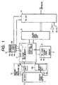
- Fig. 1 is a block diagram of a telephone apparatus of the first embodiment.
- the telephone apparatus of the first embodiment comprises a telephone circuit 10 including a speaker 14 and a microphone 15 for providing communication between a network and an operator, a sound data conversion circuit 3 for converting sound signals from the microphone 15 and from the network to sound data and converting sound data into another sound signal reproduced by the speaker 14, a control circuit 2 comprising a microprocessor, a memory 4, a memory cord receiving unit 13 including an interface circuit 13b comprising contacts to be coupled to a memory card 1 and a memory card detector 13a, and an operation panel 14, having a display 14a and ten-keys 14b, a recording command key 14c for receiving a recording command operation, and a reproducing command key 14d for receiving a reproducing command operation.
- the ten-keys 14b receives the conventional dialing operation to the telephone circuit 10.
- An operator can communicate with a third party through the microphone 15, the speaker 14, the telephone circuit 10, and the network. If the operator calls the third party, the operator dials with the operation panel 14.
- the memory card receiving unit 13 having a slot 13c can receive a memory card 1 having a predetermined size. That is, when the operator inserts the memory card 1 into the slot 13c, the memory card detector 13a detects the presence of the memory card 1 and the memory card 1 is coupled to the control circuit 2 through the interface circuit 13b having the contacts, so that the control circuit 2 can read an identification code 6 stored in the memory card 1. Then, the control circuit 2 registers the identification code in an identification code registering memory 7 therein if the recording operation is executed.
- control circuit 2 When the control circuit 2 receives a recording command from the operation panel 14 (recording mode), the control circuit 2 controls the sound data conversion circuit 3, the memory 4, the telephone circuit 10 to record the sound data from the telephone circuit 10 only when the memory card 1 is inserted. Similarly, when the control circuit 2 receives a reproducing command from the operation panel 14 (reproducing mode), the control circuit 2 controls the memory 4, the sound data conversion circuit 3, and the telephone circuit 10 to reproduce the sound data from the memory 4 using the speaker 14 only when the memory card 1 is inserted.
- the recording mode that is, the recording command is inputted when the memory card 1 is inserted, a sound signal from the microphone 15 and from the network is a/d-converted by the sound data conversion circuit 3 and the control circuit 2 stores the identification code 6 from the memory card 1 and the sound data in a data format 9 at a storing area in the memory 4.
- the control circuit 2 having an address control table 2a stores the top and end addresses of the storing area of the stored sound data.
- the reproducing mode that is, the reproducing command is inputted when the memory card 1 is inserted, the sound data is read from the memory 4 with address data from the address control table 2a and the read sound data is supplied to the speaker 14 through d/a-conversion by the sound data conversion circuit 3 and the telephone circuit 10.
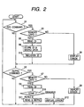
- Fig. 2 depicts a flow chart of the first embodiment showing the operation of the control circuit 2.
- the control circuit 2 checks whether the recording command is present in step s1. If there is no recording command in step s1, the control circuit 2 checks whether the reproducing command is present in step s2. If there is no reproducing command in step s2, processing returns to step s1.
- the control circuit 2 checks whether there is the memory card 1 in the memory card receiving unit 13 in step s3. If there is no memory card in the memory card receiving unit 13 in step s3, the control circuit 2 informs the operator of an erroneous operation on the display 14a in step s4. If there is the memory card 1 in the memory card receiving unit 13 in step s3, the control circuit 2 reads the identification code 6 from the memory card 1 and stores the sound data in the memory 4 having the data format 9 at the storing area. That is, the sound data 9b is stored together with the identification code 6 from the memory card 1 as the identification code 9b. In other words, the sound data 9b is stored with a correspondence with the identification code 9a.
- the control circuit 2 stores the top and end address in the address control table in step s6. In the following step s16, the control circuit 2 registers the identification code 6 from the memory card 1 in the identification code registering memory 2. After steps s4 and s16 processing proceeds to step s2.
- the control circuit 2 checks whether there is the memory card 1 in the memory card receiving unit 13 in step s7. If there is no memory card in the memory card receiving unit 13 in step s7, the control circuit 2 informs the operator of an erroneous operation on the display 14a in step s8. If there is the memory card 1 in the memory card receiving unit 13 in step s7, the control circuit 2 reads the identification code 6 from the memory card 1 and compares the read identification code 6 with the identification code 9a stored together with the desired sound data 9b in the memory 4.
- the control circuit 2 If the identification code 6 from the memory cared 1 agrees with the identification code 9a in the memory 4, the control circuit 2 reads the sound data 9b stored together with the identification code 9a in the memory 4 and reproduces it by the speaker 14 through the sound data conversion circuit 3 and the telephone circuit 10 in step s11. If the identification code 6 form the memory card 1 disagrees with the identification code 9a in the memory 4, the control circuit 2 informs the operator of an erroneous operation or an inhibited operation in step s12. After steps s8, s11, and s12 processing returns to step s1.
- the first embodiment it is inhibited to reproduce the sound data when the identification code disagrees with the registered identification code which have been registered on the recording operation.
- step s9 processing directly proceeds to step s11.
- step s11 This means the checking operation is executed only by checking the presence of the memory card 1. In this case, it is inhibited to reproduce the sound data 9b in the memory 4 when the memory card 1 is not inserted.
- the sound data is stored in the memory 4 via the control circuit 2.
- the telephone apparatus of the second embodiment has substantially the same structure as that of the first embodiment. The difference is that the control circuit 2 stores the sound data in the recording mode in consideration of the space in the memory 4.
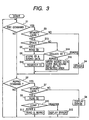
- Fig. 3 depicts a flow chart of the second embodiment showing the operation of the control circuit 2.
- Fig. 3 The operation in Fig. 3 is substantially the same as that in Fig. 2. The difference is that steps s13 to s15 are added.
- step s3 the control circuit 2 checks whether there is a space for recording the sound data in step s13. If there is a space for recording the sound data in step s13, processing proceeds to step s5 and reads the identification code 6 and stores the sound data with the identification code 6 as similar to the first embodiment.
- step s13 if there is no space for recording the sound data, the control circuit 2 collates the identification code 6 from the memory card 1 with the identification codes in the identification code registering memory 7. If there is an identification code in the identification code registering memory 7 agreeing the identification code from the memory card 1, the control circuit 2 reads the top and end addresses of the storing area of the sound data storing the identification code from the address control table 2a and stores the sound data from the sound data conversion circuit 3 at the detected storing area, that is, the control circuit 2 writes the new sound data over the sound data which have been written at the detected storing area.
- step s14 if there is no identification code in the identification code registering memory 7 agreeing the identification code 6 from the memory card 1, processing proceeds to step s4 to inform the user of an erroneous operation (no space in the memory 4) in step s4.
- the second embodiment it is inhibited to write new sound data over the old sound data in the memory 4 if the identification code in the memory card 1 disagrees with the identification codes registered in the identification code registering memory 7. That is, only recording command from the person who has recorded the sound data in the memory 4 can be received.
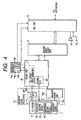
- Fig. 4 is a block diagram of a telephone apparatus of the third embodiment.
- the telephone apparatus of the third embodiment has substantially the same structure as that of the first embodiment.
- the difference is that the memory card 1 has a memory 20, the control circuit 22 has a serial interface circuit 23 for sending sound data to and receiving sound data from the memory card 1, and the memory 4 is omitted.
- an address control table 24 is generated in the memory card 1 in response to the first recording command. Then, in response to the following recording command, the address control table 24 is renewed by the control circuit 22. Further, the reproduction command is inhibited if the identification code 6 in the memory card disagrees with any one of the identification codes which have been registered in the identification code registering memory 7.
- control circuit 22 When the control circuit 22 receives the recording command from the operation panel 14, the control circuit 22 controls the sound data conversion circuit 3, the serial interface circuit 23, the telephone circuit 10 to record the sound data from the telephone circuit 10 when the memory card 1 is inserted and there is a space in the memory card 1. Then, the identification code in the memory card 1 is read from the memory card 1 and registered in the identification code registering memory 7.
- control circuit 22 controls the serial interface circuit 23, the sound data conversion circuit 3, and the telephone circuit 10 to reproduce the sound data 25 from the memory card 1 using the speaker 14 only when the memory card 1 is inserted and the identification code registered in the identification code registering memory 7 agrees with the identification code 6 from the memory card 1.
- recording mode that is, the recording command is inputted while the memory card 1 is inserted, a sound signal from the microphone 15 and from the network is a/d-converted by the sound data conversion circuit 3 and the control circuit 22 stores the sound data 25 in the memory 20 of the memory card 1. Then, the control circuit 22 sends and stores the top and end addresses of the storing area of the stored sound data to the memory card 1. If the following recording command comes from the memory card 1 of which identification code 6 has been registered, the control circuit reads the address control table 24 at first to renew the address control table 24.
- reproducing mode that is, when the reproducing command is inputted while the memory card 1 is inserted and the identification code 6 in the memory card 1 has been registered in the identification code registering memory 7, the sound data is read from the memory card 1 with address data from the address control table 24 and the read sound data is supplied to speaker 14 through d/a-conversion by the sound data conversion circuit 3 and the telephone circuit 10.
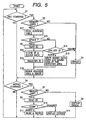
- Fig. 5 depicts a flow chart of the third embodiment showing the operation of the control circuit 22 in Fig. 4.
- the control circuit 22 checks whether the recording command is present in step s1. If there is no recording command in step s1, the control circuit 2 checks whether the reproducing command is present in step s2. If there is no reproducing command in step s2, processing returns to step s1.
- the control circuit 22 checks whether there is the memory card 1 in the memory card receiving unit 13 in step s3. If there is no memory card in the memory card receiving unit 13 in step s3, the control circuit 22 informs the operator of an erroneous operation on the display 14a in step s4. If there is the memory card 1 in the memory card receiving unit 13 in step s3, the control circuit 22 reads the address table 24 from the memory card 1 through the serial interface circuit 23 in step s17 in step s17. In the following step s13, the control circuit 22 checks whether there is a space for recording the sound data in step s13 by checking the address control table 24.
- step s13 If there is a space for recording the sound data in step s13, processing proceeds to step s5 where the control circuit 22 reads the identification code 6 in the memory card 1 and stores the sound data in the memory 20 in step s26. In the following step s16, the control circuit registers the identification code 6 from the memory card 1 in the identification code registering memory 7.
- step s13 if there is no space for recording the sound data, the control circuit 22 collates the identification code 6 from the memory card 1 with the identification codes in the identification code registering memory 7. If there is an identification code in the identification code registering memory 7 agreeing the identification code from the memory card 1, the control circuit 22 reads the top and end addresses of the storing area of the sound data storing the identification code from the address control table 24 and stores the sound data from the sound data conversion circuit 3 at the detected storing area of the memory card 1, that is, the control circuit 22 writes the new sound data over the sound data which have been written at the detected storing area of the memory card 1 in step s15.
- control circuit 2 After the steps s15 and s16, the control circuit 2 stores the top and end address in the address control table in step s18, that is, the control circuit 2 renews the address control table 24 in the memory 20 of the memory card 1 in step s18.
- step s14 if there is no identification code in the identification code registering memory 7 agreeing the identification code from the memory card 1, processing proceeds to step s4 to inform the user of an erroneous operation (no space) in step s4.
- the control circuit 22 checks whether there is the memory card 1 in the memory card receiving unit 13 in step s7. If there is no memory card in the memory card receiving unit 13 in step s7, the control circuit 22 informs the operator of an erroneous operation on the display 14a in step s8. If there is the memory card 1 in the memory card receiving unit 13 in step s7, the control circuit 22 reads the identification code 6 from the memory card 1 and compares the read identification codes with the identification code in the identification code registering memory 7 in step s19.
- step s8 If the identification code from the memory cared 1 agrees with one of the identification codes in the identification code registering memory 7, the control circuit 22 reads the sound data in the memory card 1 and reproduces it by the speaker 14 through the serial interface circuit 23, the sound data conversion circuit 3 and the telephone circuit 10. If the identification code from the memory card 1 disagrees with any of identification codes in the identification code registering memory 7, the control circuit 22 informs the operator of an erroneous operation in step s12. After step s8, s11, and s12 processing returns to step s1.
- the third embodiment it is inhibited to reproduce the sound data in the memory card 1 when the memory card is not inserted. Moreover, it is inhibited to reproduce the sound data when the identification code 6 from the memory card 1 disagrees with any one of the registered identification codes which have been registered on the recording operation, so that it is inhibited to reproduce the sound data which have been recorded in another telephone apparatus.
- Fig. 6 is a block diagram of a telephone apparatus of the fourth embodiment.
- the telephone apparatus of the fourth embodiment has substantially the same structure as that of the first embodiment.
- the communication circuit comprises a radio wave circuit 21 for providing a communication through a radio wave.
- the communication circuit 10 communicates with a network through the radio wave signal via a base station (not shown) using the radio wave circuit 21.
- Other operations are similar to the first embodiment.
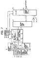
- Fig. 7 is a block diagram of a telephone apparatus of the fifth embodiment.
- the telephone apparatus of the fifth embodiment has substantially the same structure as that of the third embodiment.
- the communication circuit comprises a radio wave circuit 21 for providing a communication through a radio wave.
- the communication circuit communicates with a network through the radio wave signal via a base station (not shown) using the radio wave circuit 21.
- Other operations are similar to the third embodiment.
Landscapes
- Engineering & Computer Science (AREA)
- Signal Processing (AREA)
- Computer Security & Cryptography (AREA)
- Microelectronics & Electronic Packaging (AREA)
- Telephonic Communication Services (AREA)
- Telephone Function (AREA)
- Mobile Radio Communication Systems (AREA)
- Telephone Set Structure (AREA)
Claims (7)
- Telefonvorrichtung mit:dadurch gekennzeichnet, dass:einem Kommunikationsmittel (10, 14, 15) mit einem Tonaufnahmemittel (15) und einem Tonwiedergabemittel (10), um eine Kommunikation zwischen einem Anwender und einem Netzwerk vorzusehen und Tondaten von dem Tonaufnahmemittel und dem Netzwerk auszugeben;einem Speicherkartenaufnahmemittel (13) zum Aufnehmen einer Speicherkarte, die eine vorbestimmte Größe besitzt;einem Speicherkartenerfassungsmittel (13a) zur Erzeugung eines Erfassungssignals, wenn die Speicherkarte von dem Speicherkartenaufnahmemittel aufgenommen ist;einem Speichermittel (4) zum Speichern der Tondaten; undeinem Steuermittel (2), das auf das Speicherkartenerfassungsmittel und eine Aufzeichnungsanweisung zum Speichern der Tondaten in dem Speichermittel und zum Lesen der Tondaten von dem Speichermittel anspricht;die Speicherkarte einen Speicher aufweist, der einen Identifikationscode (6) speichert;das Steuermittel den Identifikationscode (6) von der Speicherkarte in der Telefonvorrichtung in Ansprechen auf die Aufzeichnungsanweisung liest und speichert; unddas Steuermittel in Ansprechen auf eine Wiedergabeanweisung den in der Telefonvorrichtung (9a, 7) gespeicherten Identifikationscode und den Identifikationscode von der Speicherkarte liest und den Identifikationscode von der Telefonvorrichtung mit dem Identifikationsmittel von der Speicherkarte vergleicht und die gespeicherten Tondaten wiedergibt, wenn der Identifikationscode von der Speicherkarte mit dem Identifikationscode von der Telefonvorrichtung übereinstimmt.
- Telefonvorrichtung nach Anspruch 1, wobei das Steuermittel den Identifikationscode in dem Speichermittel in Übereinstimmung mit den gespeicherten Tondaten speichert.
- Telefonvorrichtung nach Anspruch 2, wobei das Steuermittel eine Adresssteuertabelle (2a) aufweist, um Speicherbereiche der Tondaten in dem Speichermittel (4) zu steuern,
das Steuermittel (2) in Ansprechen auf die Aufzeichnungsanweisung beurteilt, ob in dem Speichermittel (4) ein Raum vorhanden ist, indem die Adresssteuertabelle (2a) überprüft wird,
das Steuermittel, wenn kein Raum vorhanden ist, den Identifikationscode von der Speicherkarte mit den Identifikationscodes von dem Speichermittel vergleicht, und
das Steuermittel, wenn der Identifikationscode von der Speicherkarte mit einem der Identifikationscodes von dem Speichermittel übereinstimmt, einen der Speicherbereiche der Tondaten sucht, die die Übereinstimmung mit dem einen der Identifikationscodes von dem Speichermittel aufweist, der mit dem Identifikationscode von der Speicherkarte übereinstimmt, und die Tondaten an dem gesuchten Speicherbereich speichert. - Telefonvorrichtung nach Anspruch 1, ferner mit einem seriellen Datenschnittstellenmittel (13b) zur Übertragung der Tondaten an die Speicherkarte, die von dem Speicherkartenaufnahmemittel aufgenommen ist.
- Telefonvorrichtung nach Anspruch 4, ferner mit einem Registriermittel (7), wobei das Steuermittel (2) den Identifikationscode (6) von der Speicherkarte in dem Registriermittel (7) in Ansprechen auf die Aufzeichnungsanweisung liest und registriert, wenn die Speicherkarte von dem Speicherkartenaufnahmemittel aufgenommen ist.
- Telefonvorrichtung nach Anspruch 5, wobei das Steuermittel (2) eine Adresssteuertabelle (24) in dem Speicher der Speicherkarte durch die serielle Schnittstelle (18b) in Ansprechen auf die Aufzeichnungsanweisung erzeugt und erneuert,
das Steuermittel beurteilt, ob ein Raum in dem Speicher vorhanden ist, in dem die Adresssteuertabelle in dem Speicher in Ansprechen auf das Aufzeichnungsmittel überprüft wird,
das Steuermittel, wenn kein Raum in dem Speicher vorhanden ist, den Identifikationscode von der Speicherkarte liest und den gelesenen Identifikationscode mit Identifikationscodes in dem Registriermittel vergleicht,
wobei das Steuermittel die Tondaten von dem Kommunikationsmittel nur speichert, wenn der gelesene Identifikationscode mit einem der Identifikationscodes übereinstimmt. - Telefonvorrichtung nach einem der vorhergehenden Ansprüche, wobei die Kommunikationsvorrichtung eine Funkwellenschaltung umfasst, um die Kommunikation durch Funkwellen vorzusehen.
Applications Claiming Priority (3)
| Application Number | Priority Date | Filing Date | Title |
|---|---|---|---|
| JP350427/96 | 1996-12-27 | ||
| JP35042796 | 1996-12-27 | ||
| JP8350427A JPH10190822A (ja) | 1996-12-27 | 1996-12-27 | 録音再生許可機能付き電話装置 |
Publications (3)
| Publication Number | Publication Date |
|---|---|
| EP0851648A2 EP0851648A2 (de) | 1998-07-01 |
| EP0851648A3 EP0851648A3 (de) | 2000-11-22 |
| EP0851648B1 true EP0851648B1 (de) | 2004-09-15 |
Family
ID=18410427
Family Applications (1)
| Application Number | Title | Priority Date | Filing Date |
|---|---|---|---|
| EP97310526A Expired - Lifetime EP0851648B1 (de) | 1996-12-27 | 1997-12-23 | Fernsprechgerät mit Aufzeichnungs- und Wiedergabefunktionen |
Country Status (5)
| Country | Link |
|---|---|
| US (1) | US6259773B1 (de) |
| EP (1) | EP0851648B1 (de) |
| JP (1) | JPH10190822A (de) |
| CN (1) | CN1096783C (de) |
| DE (1) | DE69730685T2 (de) |
Families Citing this family (11)
| Publication number | Priority date | Publication date | Assignee | Title |
|---|---|---|---|---|
| JP2000236378A (ja) | 1999-02-16 | 2000-08-29 | Matsushita Electric Ind Co Ltd | 携帯電話装置 |
| US7716077B1 (en) | 1999-11-22 | 2010-05-11 | Accenture Global Services Gmbh | Scheduling and planning maintenance and service in a network-based supply chain environment |
| US7130807B1 (en) * | 1999-11-22 | 2006-10-31 | Accenture Llp | Technology sharing during demand and supply planning in a network-based supply chain environment |
| JP2001197196A (ja) * | 2000-01-12 | 2001-07-19 | Sony Corp | 携帯端末および携帯端末の表示用情報管理方法 |
| JP2002091494A (ja) * | 2000-09-13 | 2002-03-27 | Tdk Corp | ディジタル式記録再生装置 |
| WO2002023349A1 (en) * | 2000-09-18 | 2002-03-21 | Kabushiki Kaisha Toshiba | Portable electronic medium |
| JP2002164998A (ja) * | 2000-11-27 | 2002-06-07 | Nec Corp | 録音機能を持つ携帯電話機 |
| JP4366414B2 (ja) * | 2007-04-27 | 2009-11-18 | シャープ株式会社 | 印刷制御装置、印刷システム、印刷制御方法、制御プログラム、記録媒体 |
| CN101471125B (zh) * | 2007-12-28 | 2012-03-21 | 爱国者电子科技有限公司 | 提供掉电数据保护的电子录音设备 |
| CN101471126B (zh) * | 2007-12-28 | 2011-04-27 | 北京爱国者存储科技有限责任公司 | 电子录音设备掉电的数据保护的方法 |
| JP7092843B2 (ja) * | 2019-10-31 | 2022-06-28 | アシュラント,インコーポレーテッド | 独立したコンピューティングリソースを管理し、および同期させるためのシステム、方法、装置、およびコンピュータプログラム製品 |
Family Cites Families (9)
| Publication number | Priority date | Publication date | Assignee | Title |
|---|---|---|---|---|
| JPS6141262A (ja) * | 1984-07-31 | 1986-02-27 | Omron Tateisi Electronics Co | 音声記録可能なカ−ド |
| JPS6196856A (ja) * | 1984-10-17 | 1986-05-15 | Omron Tateisi Electronics Co | Icカ−ドを用いた通話音声蓄積システム |
| JPH02305159A (ja) * | 1989-05-19 | 1990-12-18 | Toshiba Corp | 無線電話装置 |
| JPH0346454A (ja) * | 1989-07-14 | 1991-02-27 | Fujitsu Ltd | 電話通話内容の録音・再生装置 |
| JPH03167947A (ja) * | 1989-11-27 | 1991-07-19 | Omron Corp | 電話システム |
| JPH0522397A (ja) * | 1991-07-11 | 1993-01-29 | Fujitsu General Ltd | 留守番電話装置 |
| US5465401A (en) * | 1992-12-15 | 1995-11-07 | Texas Instruments Incorporated | Communication system and methods for enhanced information transfer |
| EP0744087A4 (de) * | 1994-02-10 | 1999-04-14 | Elonex Technologies Inc | Intelligentes telefon |
| KR0182939B1 (ko) * | 1995-06-28 | 1999-04-15 | 김광호 | 특정 기록포멧을 갖는 아이씨 카드 메모리 및 그로부터의 디지탈음성 기록 및 재생방법 |
-
1996
- 1996-12-27 JP JP8350427A patent/JPH10190822A/ja active Pending
-
1997
- 1997-12-22 US US08/996,218 patent/US6259773B1/en not_active Expired - Lifetime
- 1997-12-23 DE DE69730685T patent/DE69730685T2/de not_active Expired - Lifetime
- 1997-12-23 EP EP97310526A patent/EP0851648B1/de not_active Expired - Lifetime
- 1997-12-29 CN CN97126248A patent/CN1096783C/zh not_active Expired - Fee Related
Also Published As
| Publication number | Publication date |
|---|---|
| EP0851648A2 (de) | 1998-07-01 |
| JPH10190822A (ja) | 1998-07-21 |
| EP0851648A3 (de) | 2000-11-22 |
| CN1187729A (zh) | 1998-07-15 |
| CN1096783C (zh) | 2002-12-18 |
| US6259773B1 (en) | 2001-07-10 |
| DE69730685T2 (de) | 2005-08-18 |
| DE69730685D1 (de) | 2004-10-21 |
Similar Documents
| Publication | Publication Date | Title |
|---|---|---|
| US4677657A (en) | Voice recording card | |
| KR100605849B1 (ko) | 휴대용 단말기의 데이터 저장 및 재생방법 | |
| US4985913A (en) | Multiple message answering machine keyed to the incoming phone number | |
| EP0851648B1 (de) | Fernsprechgerät mit Aufzeichnungs- und Wiedergabefunktionen | |
| US6665547B1 (en) | Radio communication apparatus with telephone number registering function through speech recognition | |
| US5519764A (en) | Circuit and method for detecting error causing tones in a voice messaging system | |
| US7783324B2 (en) | Mobile communication system and devices used therefor | |
| JP3255102B2 (ja) | 無線通信装置 | |
| JP2000032169A (ja) | メモリカード付き携帯電話 | |
| KR100296986B1 (ko) | 단축다이얼링방법 | |
| KR20000044029A (ko) | 호출자 전화번호 음성출력 전화기 | |
| KR100238704B1 (ko) | 자동응답전화기에서 특정 음성 메시지 보존 방법 | |
| JP2714182B2 (ja) | コードレス電話機能付留守番電話装置 | |
| JP3519849B2 (ja) | 留守番電話機及び留守番メッセージ再生方法 | |
| JPH11308315A (ja) | 携帯電話装置 | |
| JP2956576B2 (ja) | プリペイドカード及びプリペイドカード端末装置 | |
| JP2003069671A (ja) | 携帯電話機 | |
| JP3519258B2 (ja) | 音声認識作動装置 | |
| JPH06268730A (ja) | 簡易伝言板 | |
| KR19980084040A (ko) | 외부 녹음 장치를 구비한 무선 전화기의 녹음 및 재생 방법 | |
| JP2000059491A (ja) | 電話装置 | |
| JP2002281144A (ja) | 電話機 | |
| JPH10336316A (ja) | 留守番電話機 | |
| JPH0194748A (ja) | 通話装置 | |
| JPH11112648A (ja) | 留守番機能付き装置 |
Legal Events
| Date | Code | Title | Description |
|---|---|---|---|
| PUAI | Public reference made under article 153(3) epc to a published international application that has entered the european phase |
Free format text: ORIGINAL CODE: 0009012 |
|
| 17P | Request for examination filed |
Effective date: 19980109 |
|
| AK | Designated contracting states |
Kind code of ref document: A2 Designated state(s): DE FR GB |
|
| AX | Request for extension of the european patent |
Free format text: AL;LT;LV;MK;RO;SI |
|
| PUAL | Search report despatched |
Free format text: ORIGINAL CODE: 0009013 |
|
| AK | Designated contracting states |
Kind code of ref document: A3 Designated state(s): AT BE CH DE DK ES FI FR GB GR IE IT LI LU MC NL PT SE |
|
| AX | Request for extension of the european patent |
Free format text: AL;LT;LV;MK;RO;SI |
|
| RIC1 | Information provided on ipc code assigned before grant |
Free format text: 7H 04M 1/65 A, 7H 04M 1/66 B |
|
| AKX | Designation fees paid |
Free format text: DE FR GB |
|
| 17Q | First examination report despatched |
Effective date: 20030219 |
|
| GRAP | Despatch of communication of intention to grant a patent |
Free format text: ORIGINAL CODE: EPIDOSNIGR1 |
|
| GRAS | Grant fee paid |
Free format text: ORIGINAL CODE: EPIDOSNIGR3 |
|
| GRAA | (expected) grant |
Free format text: ORIGINAL CODE: 0009210 |
|
| AK | Designated contracting states |
Kind code of ref document: B1 Designated state(s): DE FR GB |
|
| REG | Reference to a national code |
Ref country code: GB Ref legal event code: FG4D |
|
| REF | Corresponds to: |
Ref document number: 69730685 Country of ref document: DE Date of ref document: 20041021 Kind code of ref document: P |
|
| ET | Fr: translation filed | ||
| PLBE | No opposition filed within time limit |
Free format text: ORIGINAL CODE: 0009261 |
|
| STAA | Information on the status of an ep patent application or granted ep patent |
Free format text: STATUS: NO OPPOSITION FILED WITHIN TIME LIMIT |
|
| 26N | No opposition filed |
Effective date: 20050616 |
|
| PGFP | Annual fee paid to national office [announced via postgrant information from national office to epo] |
Ref country code: GB Payment date: 20121219 Year of fee payment: 16 |
|
| PGFP | Annual fee paid to national office [announced via postgrant information from national office to epo] |
Ref country code: FR Payment date: 20130107 Year of fee payment: 16 |
|
| PGFP | Annual fee paid to national office [announced via postgrant information from national office to epo] |
Ref country code: DE Payment date: 20121219 Year of fee payment: 16 |
|
| REG | Reference to a national code |
Ref country code: DE Ref legal event code: R119 Ref document number: 69730685 Country of ref document: DE |
|
| GBPC | Gb: european patent ceased through non-payment of renewal fee |
Effective date: 20131223 |
|
| REG | Reference to a national code |
Ref country code: DE Ref legal event code: R119 Ref document number: 69730685 Country of ref document: DE Effective date: 20140701 |
|
| REG | Reference to a national code |
Ref country code: FR Ref legal event code: ST Effective date: 20140829 |
|
| PG25 | Lapsed in a contracting state [announced via postgrant information from national office to epo] |
Ref country code: DE Free format text: LAPSE BECAUSE OF NON-PAYMENT OF DUE FEES Effective date: 20140701 |
|
| PG25 | Lapsed in a contracting state [announced via postgrant information from national office to epo] |
Ref country code: GB Free format text: LAPSE BECAUSE OF NON-PAYMENT OF DUE FEES Effective date: 20131223 Ref country code: FR Free format text: LAPSE BECAUSE OF NON-PAYMENT OF DUE FEES Effective date: 20131231 |