EP0849818A2 - Cellule électrochimique à ensemble d'électrodes enroulées en spirale résistante aux chocs mécaniques - Google Patents
Cellule électrochimique à ensemble d'électrodes enroulées en spirale résistante aux chocs mécaniques Download PDFInfo
- Publication number
- EP0849818A2 EP0849818A2 EP97309118A EP97309118A EP0849818A2 EP 0849818 A2 EP0849818 A2 EP 0849818A2 EP 97309118 A EP97309118 A EP 97309118A EP 97309118 A EP97309118 A EP 97309118A EP 0849818 A2 EP0849818 A2 EP 0849818A2
- Authority
- EP
- European Patent Office
- Prior art keywords
- support member
- electrode assembly
- spirally
- casing
- electrochemical cell
- Prior art date
- Legal status (The legal status is an assumption and is not a legal conclusion. Google has not performed a legal analysis and makes no representation as to the accuracy of the status listed.)
- Granted
Links
Images
Classifications
-
- H—ELECTRICITY
- H01—ELECTRIC ELEMENTS
- H01M—PROCESSES OR MEANS, e.g. BATTERIES, FOR THE DIRECT CONVERSION OF CHEMICAL ENERGY INTO ELECTRICAL ENERGY
- H01M10/00—Secondary cells; Manufacture thereof
- H01M10/04—Construction or manufacture in general
- H01M10/0413—Large-sized flat cells or batteries for motive or stationary systems with plate-like electrodes
-
- H—ELECTRICITY
- H01—ELECTRIC ELEMENTS
- H01M—PROCESSES OR MEANS, e.g. BATTERIES, FOR THE DIRECT CONVERSION OF CHEMICAL ENERGY INTO ELECTRICAL ENERGY
- H01M10/00—Secondary cells; Manufacture thereof
- H01M10/04—Construction or manufacture in general
- H01M10/0431—Cells with wound or folded electrodes
-
- H—ELECTRICITY
- H01—ELECTRIC ELEMENTS
- H01M—PROCESSES OR MEANS, e.g. BATTERIES, FOR THE DIRECT CONVERSION OF CHEMICAL ENERGY INTO ELECTRICAL ENERGY
- H01M10/00—Secondary cells; Manufacture thereof
- H01M10/04—Construction or manufacture in general
- H01M10/0468—Compression means for stacks of electrodes and separators
-
- H—ELECTRICITY
- H01—ELECTRIC ELEMENTS
- H01M—PROCESSES OR MEANS, e.g. BATTERIES, FOR THE DIRECT CONVERSION OF CHEMICAL ENERGY INTO ELECTRICAL ENERGY
- H01M6/00—Primary cells; Manufacture thereof
- H01M6/04—Cells with aqueous electrolyte
- H01M6/06—Dry cells, i.e. cells wherein the electrolyte is rendered non-fluid
- H01M6/10—Dry cells, i.e. cells wherein the electrolyte is rendered non-fluid with wound or folded electrodes
-
- H—ELECTRICITY
- H01—ELECTRIC ELEMENTS
- H01M—PROCESSES OR MEANS, e.g. BATTERIES, FOR THE DIRECT CONVERSION OF CHEMICAL ENERGY INTO ELECTRICAL ENERGY
- H01M10/00—Secondary cells; Manufacture thereof
- H01M10/05—Accumulators with non-aqueous electrolyte
-
- Y—GENERAL TAGGING OF NEW TECHNOLOGICAL DEVELOPMENTS; GENERAL TAGGING OF CROSS-SECTIONAL TECHNOLOGIES SPANNING OVER SEVERAL SECTIONS OF THE IPC; TECHNICAL SUBJECTS COVERED BY FORMER USPC CROSS-REFERENCE ART COLLECTIONS [XRACs] AND DIGESTS
- Y02—TECHNOLOGIES OR APPLICATIONS FOR MITIGATION OR ADAPTATION AGAINST CLIMATE CHANGE
- Y02E—REDUCTION OF GREENHOUSE GAS [GHG] EMISSIONS, RELATED TO ENERGY GENERATION, TRANSMISSION OR DISTRIBUTION
- Y02E60/00—Enabling technologies; Technologies with a potential or indirect contribution to GHG emissions mitigation
- Y02E60/10—Energy storage using batteries
-
- Y—GENERAL TAGGING OF NEW TECHNOLOGICAL DEVELOPMENTS; GENERAL TAGGING OF CROSS-SECTIONAL TECHNOLOGIES SPANNING OVER SEVERAL SECTIONS OF THE IPC; TECHNICAL SUBJECTS COVERED BY FORMER USPC CROSS-REFERENCE ART COLLECTIONS [XRACs] AND DIGESTS
- Y02—TECHNOLOGIES OR APPLICATIONS FOR MITIGATION OR ADAPTATION AGAINST CLIMATE CHANGE
- Y02P—CLIMATE CHANGE MITIGATION TECHNOLOGIES IN THE PRODUCTION OR PROCESSING OF GOODS
- Y02P70/00—Climate change mitigation technologies in the production process for final industrial or consumer products
- Y02P70/50—Manufacturing or production processes characterised by the final manufactured product
-
- Y—GENERAL TAGGING OF NEW TECHNOLOGICAL DEVELOPMENTS; GENERAL TAGGING OF CROSS-SECTIONAL TECHNOLOGIES SPANNING OVER SEVERAL SECTIONS OF THE IPC; TECHNICAL SUBJECTS COVERED BY FORMER USPC CROSS-REFERENCE ART COLLECTIONS [XRACs] AND DIGESTS
- Y10—TECHNICAL SUBJECTS COVERED BY FORMER USPC
- Y10T—TECHNICAL SUBJECTS COVERED BY FORMER US CLASSIFICATION
- Y10T29/00—Metal working
- Y10T29/49—Method of mechanical manufacture
- Y10T29/49002—Electrical device making
- Y10T29/49108—Electric battery cell making
Definitions
- the present invention relates generally to electrochemical cells or batteries. More particularly, the present invention relates to electrochemical cells which have spirally-wound electrode and separator assemblies.
- patent 5,114,804 has tightly spirally-wound electrodes separated by spirally-wound separator layers, one therebetween and the other on the outside, wherein the tension on the separator layers is maintained by a c-clamp applied circumferentially about the spiral winding to provide a desired compressive load.
- Electrochemical cells are often used as power sources in industrial applications which may subject them to high levels of mechanical stress such as shock and vibration.
- shock and vibration A notable example is in the oil and gas industry where "measurement while drilling" applications utilize nonaqueous cells of both solid and liquid cathode chemistries. Under these conditions, cell failure can occur due to the movement of internal components relative to each other or to the cell case. Commonly, the movement may result in either a short circuit or discontinuity caused by the severing of an internal connection. It is considered desirable that a cell which contains a spirally-wound electrode and separator assembly and which is used in such a high shock and vibration application not be damaged by such mechanical shocks.
- a unique problem is encountered with respect to spirally-wound electrode and separator assemblies in that only the periphery of the spiral winding is positioned to be suitably anchored to the case, with the result that the unsupported central portion of the winding may undesirably telescope outwardly when the cell is subjected to mechanical shocks such as impacts, acceleration, or deceleration and thereby become damaged.
- a resilient member is disposed between the spirally-wound assembly and at least one of the end walls of the casing.
- Fig. 1 is a side view of an electrochemical cell which embodies the present invention.
- Figs. 2 and 3 are opposite end views respectively thereof.
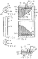
- Fig. 4 is an enlarged side view, with portions of the casing broken away and partially in section, thereof.
- Fig. 5 is a partial view similar to that of Fig. 4 of an alternative embodiment of the present invention.
- Cell 10 a spirally-wound electrochemical cell which may, for example, be a lithium battery for use in a "measurement while drilling" application where it may be subjected to high levels of shock and vibration.
- Cell 10 includes a hollow casing 12 having a cylindrically-shaped side wall 14 closed at the top end (as seen in the drawings) by an end wall or header 18, which may be integral therewith.
- the lower end of the cell 10 is closed by a lid 16 which may be welded to the side wall 14 after the components described hereinafter are assembled therein.
- the casing 12 as well as lid 16 is made of electrically conductive material such as stainless steel and, being electrically conductive, provides one terminal or contact, shown as the negative terminal in Fig.
- the other electrical terminal or contact shown as the positive terminal in Fig. 1, is provided by a conductor or pin 20 extending from within the cell 10 and centrally through the upper header 18.
- Pin 20 is insulated electrically from the metal header 18 by an insulator and seal structure 22.
- Pin 20 and seal 22 are typically of a corrosion resistant pin-glass combination such as molybdenum and Ta23 glass.
- An electrolyte fill opening is provided in the header 18 and is closed by a ball and cap, as illustrated at 24, welded or otherwise secured in place after the cell 10 has been filled with an activating electrolytic solution (not shown), as is well known to those skilled in the art and shown in greater detail in the aforesaid Takeuchi patent.
- the cell 10 includes an electrode assembly, illustrated generally at 30, in the casing 12 including a positive electrode 32 and a negative electrode 34 which are separated from each other by an insulative separator material 36.
- the electrode assembly 30 is of a spirally-wound or "jellyroll" configuration.
- An electrical lead 38 or other suitable means connects the carbon electrode 32 to the positive terminal 20.
- the lithium electrode is in electrical contact with the casing, i.e., negative terminal 12.
- anchoring of the electrode and separator assembly 30 may be limited to the periphery thereof.
- the central portion of the assembly 30 may tend to telescope outwardly under mechanical shocks and be damaged.
- a resilient member is disposed between the assembly 30 and at least one but preferably each of the end walls 16 and 18 for resiliently dissipating (shock absorbing) mechanical forces acting to otherwise cause axial movements of the spirally-wound assembly 30, i.e., movements in a direction toward one of the end walls 16 and 18.
- each insulator 42 Disposed adjacent each end of the electrode and separator assembly 30 is a honeycomb or other suitable insulator 42. Overlying each insulator 42 is an insulator sheet 50, which may, for example, be one identified as a E-TFE insulator, sold by Wilson Greatbatch Ltd. of Clarence, New York, the assignee of the present invention.
- the terminal 20 extends through an aperture 48 in the upper insulator sheet 50 to provide access for connection of the lead 38 thereto.
- a wave spring 52 for dissipating the mechanical forces acting to otherwise undersirably cause axial movements of the spirally-wound assembly 30.
- a suitable wave spring is one identified as a 3-wave overlap type and sold by Smalley Steel Ring Company of Wheeling, Illinois.
- a reliable shock-absorbing cell may be assembled easily, quickly, and inexpensively.
- this invention is not limited to the use of wave springs for shock-absorbing, but other suitable springs or other resilient members for dissipating the mechanical forces are meant to come within the scope of the present invention.
- a honeycomb or other suitable insulator 62 is disposed adjacent the header 18 and has an aperture 64 for receiving the terminal 20.
- an insulative resilient pad 66 Disposed between the insulator 62 and the spirally-wound assembly 30 is an insulative resilient pad 66 such as, for example, a Goretex pad sold by W.L. Gore and Associates of Elkton, Maryland.
- An aperture 68 is provided in the pad 66 for receiving the lead 38.
Landscapes
- Engineering & Computer Science (AREA)
- Manufacturing & Machinery (AREA)
- Chemical & Material Sciences (AREA)
- Chemical Kinetics & Catalysis (AREA)
- Electrochemistry (AREA)
- General Chemical & Material Sciences (AREA)
- Secondary Cells (AREA)
- Primary Cells (AREA)
Applications Claiming Priority (2)
| Application Number | Priority Date | Filing Date | Title |
|---|---|---|---|
| US768306 | 1996-12-17 | ||
| US08/768,306 US5756229A (en) | 1996-12-17 | 1996-12-17 | Electrochemical cell having mechanical shock tolerance |
Publications (3)
| Publication Number | Publication Date |
|---|---|
| EP0849818A2 true EP0849818A2 (fr) | 1998-06-24 |
| EP0849818A3 EP0849818A3 (fr) | 1999-06-23 |
| EP0849818B1 EP0849818B1 (fr) | 2003-02-19 |
Family
ID=25082118
Family Applications (1)
| Application Number | Title | Priority Date | Filing Date |
|---|---|---|---|
| EP97309118A Expired - Lifetime EP0849818B1 (fr) | 1996-12-17 | 1997-11-13 | Cellule électrochimique à ensemble d'électrodes enroulées en spirale résistante aux chocs mécaniques |
Country Status (5)
| Country | Link |
|---|---|
| US (1) | US5756229A (fr) |
| EP (1) | EP0849818B1 (fr) |
| JP (1) | JPH10189027A (fr) |
| AU (1) | AU4837597A (fr) |
| DE (1) | DE69719160T2 (fr) |
Cited By (2)
| Publication number | Priority date | Publication date | Assignee | Title |
|---|---|---|---|---|
| EP1548859A2 (fr) * | 1999-07-15 | 2005-06-29 | BLACK & DECKER INC. | Module de batterie et son procédé de fabrication |
| DE102013215007A1 (de) | 2013-07-31 | 2015-02-05 | Robert Bosch Gmbh | Akkumulator mit gewickelter Elektrodenkonfiguration und optimierter Wärmeableitung |
Families Citing this family (13)
| Publication number | Priority date | Publication date | Assignee | Title |
|---|---|---|---|---|
| KR100416080B1 (ko) * | 1996-09-25 | 2004-03-26 | 삼성에스디아이 주식회사 | 팽창방지보강구조를갖는전지 |
| JP3565207B2 (ja) * | 2002-02-27 | 2004-09-15 | 日産自動車株式会社 | 電池パック |
| US7586736B2 (en) * | 2005-07-11 | 2009-09-08 | Micro Power Electronics Inc. | Electrical insulation system and method for electrical power storage component separation |
| US8252441B2 (en) * | 2007-08-31 | 2012-08-28 | Micro Power Electronics, Inc. | Spacers for fixing battery cells within a battery package casing and associated systems and methods |
| DE102008055161A1 (de) * | 2008-12-29 | 2010-07-01 | Robert Bosch Gmbh | Batteriemodul |
| US8709632B2 (en) * | 2009-11-13 | 2014-04-29 | Samsung Sdi Co., Ltd. | Battery module |
| JP5804323B2 (ja) * | 2011-01-07 | 2015-11-04 | 株式会社Gsユアサ | 蓄電素子及び蓄電装置 |
| US9083027B2 (en) | 2011-03-09 | 2015-07-14 | Schlumberger Technology Corporation | Point contact thermal isolation |
| JP5719859B2 (ja) * | 2012-02-29 | 2015-05-20 | 株式会社半導体エネルギー研究所 | 蓄電装置 |
| US20150140371A1 (en) * | 2013-10-14 | 2015-05-21 | 24M Technologies, Inc. | Curved battery container |
| US10062882B2 (en) | 2015-10-16 | 2018-08-28 | Bosch Battery Systems Llc | Force generating assembly for a battery pack |
| EP3958391A1 (fr) | 2020-08-21 | 2022-02-23 | Greatbatch Ltd. | Broche de terminal à joint verre-métal pour une cellule électrochimique |
| KR20230039264A (ko) * | 2021-09-14 | 2023-03-21 | 주식회사 엘지에너지솔루션 | 이차 전지 및 이를 포함하는 전지 모듈 |
Citations (11)
| Publication number | Priority date | Publication date | Assignee | Title |
|---|---|---|---|---|
| US3429747A (en) * | 1965-12-11 | 1969-02-25 | Varta Ag | Electric cell |
| GB1165900A (en) * | 1965-12-01 | 1969-10-01 | Texas Instruments Inc | Electrical Cell |
| JPS59111259A (ja) * | 1982-12-16 | 1984-06-27 | Toshiba Battery Co Ltd | 円筒形非水電解液電池 |
| JPS6091571A (ja) * | 1983-10-25 | 1985-05-22 | Shin Kobe Electric Mach Co Ltd | 密閉形アルカリ蓄電池の製造法 |
| JPS617562A (ja) * | 1984-06-20 | 1986-01-14 | Sanyo Electric Co Ltd | アルカリ蓄電池 |
| JPS62198050A (ja) * | 1986-02-25 | 1987-09-01 | Shin Kobe Electric Mach Co Ltd | 密閉式ニツケル・カドミウム蓄電池の製造法 |
| JPS6386251A (ja) * | 1986-09-29 | 1988-04-16 | Shin Kobe Electric Mach Co Ltd | 密閉形アルカリ蓄電池 |
| JPH01281675A (ja) * | 1988-05-09 | 1989-11-13 | Fuji Elelctrochem Co Ltd | 電池 |
| EP0391720A2 (fr) * | 1989-04-05 | 1990-10-10 | Eveready Battery Company, Inc. | Assemblage d'électrodes |
| JPH06203823A (ja) * | 1993-01-07 | 1994-07-22 | Japan Storage Battery Co Ltd | 電 池 |
| US5474859A (en) * | 1995-02-13 | 1995-12-12 | Wilson Greatbatch Ltd. | Electrochemical cell design for use under high shock and vibration conditions |
Family Cites Families (20)
| Publication number | Priority date | Publication date | Assignee | Title |
|---|---|---|---|---|
| US1949558A (en) * | 1929-04-08 | 1934-03-06 | Gould Storage Battery Corp | Replacement unit shipping structure |
| US2396534A (en) * | 1943-09-02 | 1946-03-12 | Harm C Rose | Battery pack |
| US3042733A (en) * | 1960-05-19 | 1962-07-03 | Union Carbide Corp | Battery construction |
| US4184007A (en) * | 1978-12-15 | 1980-01-15 | Union Carbide Corporation | Nonaqueous battery construction |
| US5114804A (en) * | 1981-08-13 | 1992-05-19 | Moli Energy Limited | Battery and method of making the battery |
| US4430390A (en) * | 1982-09-23 | 1984-02-07 | Engelhard Corporation | Compact fuel cell stack |
| FR2542926B1 (fr) * | 1983-03-16 | 1986-11-07 | Sanyo Electric Co | Dispositif de preservation pour batterie d'accumulateurs au plomb |
| JPS61124067A (ja) * | 1984-11-20 | 1986-06-11 | Sanyo Electric Co Ltd | 容器収納型燃料電池の耐振装置 |
| US4714439A (en) * | 1986-07-03 | 1987-12-22 | Motorola, Inc. | Electrical connector |
| US4874678A (en) * | 1987-12-10 | 1989-10-17 | Westinghouse Electric Corp. | Elongated solid electrolyte cell configurations and flexible connections therefor |
| JPH0514462Y2 (fr) * | 1988-02-29 | 1993-04-16 | ||
| US4871628A (en) * | 1988-10-14 | 1989-10-03 | Parker David H | Battery terminal post protector |
| US5149602A (en) * | 1991-06-20 | 1992-09-22 | Motorola, Inc. | Self-correcting cell locating compressive pad |
| US5187031A (en) * | 1991-08-07 | 1993-02-16 | Globe-Union Inc. | Anti-vibration plaque for a battery |
| DE4218381C1 (fr) * | 1992-06-04 | 1993-05-13 | Daimler-Benz Aktiengesellschaft, 7000 Stuttgart, De | |
| US5366823A (en) * | 1992-12-17 | 1994-11-22 | United Technologies Corporation | Metal compression pad |
| US5324565A (en) * | 1992-12-17 | 1994-06-28 | United Technologies Corporation | Conductive elastomeric compression pad for use in electrolysis cells |
| US5389457A (en) * | 1993-08-09 | 1995-02-14 | Eveready Battery Company, Inc. | Gas filled collapsible member within anode to accommodate expansion of anode |
| US5346786A (en) * | 1994-03-21 | 1994-09-13 | Hodgetts Philip J | Modular rack mounted battery system |
| US5384212A (en) * | 1994-04-25 | 1995-01-24 | Globe-Union Inc. | Flex-rib plaques for batteries |
-
1996
- 1996-12-17 US US08/768,306 patent/US5756229A/en not_active Expired - Lifetime
-
1997
- 1997-11-13 DE DE69719160T patent/DE69719160T2/de not_active Expired - Lifetime
- 1997-11-13 EP EP97309118A patent/EP0849818B1/fr not_active Expired - Lifetime
- 1997-11-26 JP JP9342260A patent/JPH10189027A/ja active Pending
- 1997-12-15 AU AU48375/97A patent/AU4837597A/en not_active Abandoned
Patent Citations (12)
| Publication number | Priority date | Publication date | Assignee | Title |
|---|---|---|---|---|
| GB1165900A (en) * | 1965-12-01 | 1969-10-01 | Texas Instruments Inc | Electrical Cell |
| US3429747A (en) * | 1965-12-11 | 1969-02-25 | Varta Ag | Electric cell |
| DE1496345A1 (de) * | 1965-12-11 | 1969-04-10 | Varta Ag | Galvanische Zelle mit Wickelelektroden |
| JPS59111259A (ja) * | 1982-12-16 | 1984-06-27 | Toshiba Battery Co Ltd | 円筒形非水電解液電池 |
| JPS6091571A (ja) * | 1983-10-25 | 1985-05-22 | Shin Kobe Electric Mach Co Ltd | 密閉形アルカリ蓄電池の製造法 |
| JPS617562A (ja) * | 1984-06-20 | 1986-01-14 | Sanyo Electric Co Ltd | アルカリ蓄電池 |
| JPS62198050A (ja) * | 1986-02-25 | 1987-09-01 | Shin Kobe Electric Mach Co Ltd | 密閉式ニツケル・カドミウム蓄電池の製造法 |
| JPS6386251A (ja) * | 1986-09-29 | 1988-04-16 | Shin Kobe Electric Mach Co Ltd | 密閉形アルカリ蓄電池 |
| JPH01281675A (ja) * | 1988-05-09 | 1989-11-13 | Fuji Elelctrochem Co Ltd | 電池 |
| EP0391720A2 (fr) * | 1989-04-05 | 1990-10-10 | Eveready Battery Company, Inc. | Assemblage d'électrodes |
| JPH06203823A (ja) * | 1993-01-07 | 1994-07-22 | Japan Storage Battery Co Ltd | 電 池 |
| US5474859A (en) * | 1995-02-13 | 1995-12-12 | Wilson Greatbatch Ltd. | Electrochemical cell design for use under high shock and vibration conditions |
Non-Patent Citations (7)
| Title |
|---|
| PATENT ABSTRACTS OF JAPAN vol. 008, no. 229 (E-273), 20 October 1984 -& JP 59 111259 A (TOSHIBA DENCHI KK), 27 June 1984 * |
| PATENT ABSTRACTS OF JAPAN vol. 009, no. 240 (E-345), 26 September 1985 -& JP 60 091571 A (SHINKOUBE DENKI KK), 22 May 1985 * |
| PATENT ABSTRACTS OF JAPAN vol. 010, no. 145 (E-407), 28 May 1986 -& JP 61 007562 A (SANYO DENKI KK), 14 January 1986 * |
| PATENT ABSTRACTS OF JAPAN vol. 012, no. 049 (E-582), 13 February 1988 -& JP 62 198050 A (SHIN KOBE ELECTRIC MACH CO LTD), 1 September 1987 * |
| PATENT ABSTRACTS OF JAPAN vol. 012, no. 320 (E-651), 30 August 1988 -& JP 63 086251 A (SHIN KOBE ELECTRIC MACH CO LTD), 16 April 1988 * |
| PATENT ABSTRACTS OF JAPAN vol. 014, no. 062 (E-0883), 5 February 1990 -& JP 01 281675 A (FUJI ELELCTROCHEM CO LTD), 13 November 1989 * |
| PATENT ABSTRACTS OF JAPAN vol. 018, no. 551 (E-1619), 20 October 1994 -& JP 06 203823 A (JAPAN STORAGE BATTERY CO LTD), 22 July 1994 * |
Cited By (3)
| Publication number | Priority date | Publication date | Assignee | Title |
|---|---|---|---|---|
| EP1548859A2 (fr) * | 1999-07-15 | 2005-06-29 | BLACK & DECKER INC. | Module de batterie et son procédé de fabrication |
| EP1548859A3 (fr) * | 1999-07-15 | 2005-11-09 | BLACK & DECKER INC. | Module de batterie et son procédé de fabrication |
| DE102013215007A1 (de) | 2013-07-31 | 2015-02-05 | Robert Bosch Gmbh | Akkumulator mit gewickelter Elektrodenkonfiguration und optimierter Wärmeableitung |
Also Published As
| Publication number | Publication date |
|---|---|
| EP0849818A3 (fr) | 1999-06-23 |
| EP0849818B1 (fr) | 2003-02-19 |
| US5756229A (en) | 1998-05-26 |
| AU4837597A (en) | 1998-06-18 |
| DE69719160D1 (de) | 2003-03-27 |
| JPH10189027A (ja) | 1998-07-21 |
| DE69719160T2 (de) | 2003-08-21 |
Similar Documents
| Publication | Publication Date | Title |
|---|---|---|
| EP0849818B1 (fr) | Cellule électrochimique à ensemble d'électrodes enroulées en spirale résistante aux chocs mécaniques | |
| JP5275298B2 (ja) | 二次電池 | |
| KR101182284B1 (ko) | 이차 전지 | |
| US4663247A (en) | Coiled electrode assembly cell construction with pressure contact member | |
| EP1717878B1 (fr) | Noyau pour une pile secondaire au lithium cylindrique | |
| US7192671B2 (en) | Battery having nonconductive core | |
| US5474859A (en) | Electrochemical cell design for use under high shock and vibration conditions | |
| JPH1083805A (ja) | 円筒形電気化学電池 | |
| EP0936691B1 (fr) | Pile électrochimique enroulée à noyau creux | |
| US20060051665A1 (en) | Electrochemical cell presenting two current output terminals on a wall of its container | |
| US6207320B1 (en) | Cap assembly of secondary battery | |
| CN1281589A (zh) | 棱柱形电化学电池与电池组 | |
| KR20210143851A (ko) | 이차 전지 | |
| EP2048723B1 (fr) | Module de batterie | |
| US6548204B1 (en) | Sealed battery | |
| CN1235382A (zh) | 方形蓄电池的盖组件 | |
| KR0183634B1 (ko) | 전지용 단자 케이스 | |
| US8993139B2 (en) | Sealed secondary battery | |
| GB2042788A (en) | A cylindrical electric cell | |
| EP0810677A1 (fr) | Batterie de faible epaisseur | |
| KR100322099B1 (ko) | 각형 이차 전지 | |
| JP2006100214A (ja) | 電池とその製造方法 | |
| KR100319107B1 (ko) | 밀폐전지 및 그 제조방법 | |
| JP7049586B2 (ja) | 電池 | |
| US20220223987A1 (en) | Cylindrical Secondary Battery Including Positive Electrode Tab Fixing Member |
Legal Events
| Date | Code | Title | Description |
|---|---|---|---|
| PUAI | Public reference made under article 153(3) epc to a published international application that has entered the european phase |
Free format text: ORIGINAL CODE: 0009012 |
|
| AK | Designated contracting states |
Kind code of ref document: A2 Designated state(s): CH DE FR GB IT LI NL SE |
|
| AX | Request for extension of the european patent |
Free format text: AL;LT;LV;MK;RO;SI |
|
| PUAL | Search report despatched |
Free format text: ORIGINAL CODE: 0009013 |
|
| AK | Designated contracting states |
Kind code of ref document: A3 Designated state(s): AT BE CH DE DK ES FI FR GB GR IE IT LI LU MC NL PT SE |
|
| AX | Request for extension of the european patent |
Free format text: AL;LT;LV;MK;RO;SI |
|
| RIC1 | Information provided on ipc code assigned before grant |
Free format text: 6H 01M 6/10 A, 6H 01M 10/04 B |
|
| 17P | Request for examination filed |
Effective date: 19991215 |
|
| AKX | Designation fees paid |
Free format text: CH DE FR GB IT LI NL SE |
|
| 17Q | First examination report despatched |
Effective date: 20010420 |
|
| GRAG | Despatch of communication of intention to grant |
Free format text: ORIGINAL CODE: EPIDOS AGRA |
|
| GRAG | Despatch of communication of intention to grant |
Free format text: ORIGINAL CODE: EPIDOS AGRA |
|
| GRAH | Despatch of communication of intention to grant a patent |
Free format text: ORIGINAL CODE: EPIDOS IGRA |
|
| GRAH | Despatch of communication of intention to grant a patent |
Free format text: ORIGINAL CODE: EPIDOS IGRA |
|
| RTI1 | Title (correction) |
Free format text: ELECTROCHEMICAL CELL WITH SPIRALLY WOUND ELECTRODE ASSEMBLY HAVING MECHANICAL SHOCK TOLERENCE |
|
| GRAA | (expected) grant |
Free format text: ORIGINAL CODE: 0009210 |
|
| RIN1 | Information on inventor provided before grant (corrected) |
Inventor name: KREHL, PAUL W. Inventor name: WUTZ, PHILIP S. Inventor name: PYSZCZEK, MICHAEL F. |
|
| AK | Designated contracting states |
Designated state(s): CH DE FR GB IT LI NL SE |
|
| REG | Reference to a national code |
Ref country code: GB Ref legal event code: FG4D |
|
| REG | Reference to a national code |
Ref country code: CH Ref legal event code: NV Representative=s name: ISLER & PEDRAZZINI AG Ref country code: CH Ref legal event code: EP |
|
| REF | Corresponds to: |
Ref document number: 69719160 Country of ref document: DE Date of ref document: 20030327 Kind code of ref document: P |
|
| ET | Fr: translation filed | ||
| PLBE | No opposition filed within time limit |
Free format text: ORIGINAL CODE: 0009261 |
|
| STAA | Information on the status of an ep patent application or granted ep patent |
Free format text: STATUS: NO OPPOSITION FILED WITHIN TIME LIMIT |
|
| 26N | No opposition filed |
Effective date: 20031120 |
|
| PGFP | Annual fee paid to national office [announced via postgrant information from national office to epo] |
Ref country code: NL Payment date: 20041112 Year of fee payment: 8 |
|
| PGFP | Annual fee paid to national office [announced via postgrant information from national office to epo] |
Ref country code: CH Payment date: 20041122 Year of fee payment: 8 |
|
| PG25 | Lapsed in a contracting state [announced via postgrant information from national office to epo] |
Ref country code: IT Free format text: LAPSE BECAUSE OF NON-PAYMENT OF DUE FEES Effective date: 20051113 |
|
| PG25 | Lapsed in a contracting state [announced via postgrant information from national office to epo] |
Ref country code: LI Free format text: LAPSE BECAUSE OF NON-PAYMENT OF DUE FEES Effective date: 20051130 Ref country code: CH Free format text: LAPSE BECAUSE OF NON-PAYMENT OF DUE FEES Effective date: 20051130 |
|
| PG25 | Lapsed in a contracting state [announced via postgrant information from national office to epo] |
Ref country code: NL Free format text: LAPSE BECAUSE OF NON-PAYMENT OF DUE FEES Effective date: 20060601 |
|
| REG | Reference to a national code |
Ref country code: CH Ref legal event code: PL |
|
| NLV4 | Nl: lapsed or anulled due to non-payment of the annual fee |
Effective date: 20060601 |
|
| PGFP | Annual fee paid to national office [announced via postgrant information from national office to epo] |
Ref country code: SE Payment date: 20091127 Year of fee payment: 13 |
|
| REG | Reference to a national code |
Ref country code: SE Ref legal event code: EUG |
|
| PG25 | Lapsed in a contracting state [announced via postgrant information from national office to epo] |
Ref country code: SE Free format text: LAPSE BECAUSE OF NON-PAYMENT OF DUE FEES Effective date: 20101114 |
|
| REG | Reference to a national code |
Ref country code: FR Ref legal event code: PLFP Year of fee payment: 19 |
|
| REG | Reference to a national code |
Ref country code: FR Ref legal event code: PLFP Year of fee payment: 20 |
|
| PGFP | Annual fee paid to national office [announced via postgrant information from national office to epo] |
Ref country code: DE Payment date: 20161108 Year of fee payment: 20 Ref country code: GB Payment date: 20161109 Year of fee payment: 20 Ref country code: FR Payment date: 20161014 Year of fee payment: 20 |
|
| REG | Reference to a national code |
Ref country code: DE Ref legal event code: R071 Ref document number: 69719160 Country of ref document: DE |
|
| REG | Reference to a national code |
Ref country code: GB Ref legal event code: PE20 Expiry date: 20171112 |
|
| PG25 | Lapsed in a contracting state [announced via postgrant information from national office to epo] |
Ref country code: GB Free format text: LAPSE BECAUSE OF EXPIRATION OF PROTECTION Effective date: 20171112 |