EP0846667A2 - Keramikteile und Verfahren zu ihren Herstellung - Google Patents
Keramikteile und Verfahren zu ihren Herstellung Download PDFInfo
- Publication number
- EP0846667A2 EP0846667A2 EP97309690A EP97309690A EP0846667A2 EP 0846667 A2 EP0846667 A2 EP 0846667A2 EP 97309690 A EP97309690 A EP 97309690A EP 97309690 A EP97309690 A EP 97309690A EP 0846667 A2 EP0846667 A2 EP 0846667A2
- Authority
- EP
- European Patent Office
- Prior art keywords
- machined
- sintered
- exposed
- ceramic
- ceramic part
- Prior art date
- Legal status (The legal status is an assumption and is not a legal conclusion. Google has not performed a legal analysis and makes no representation as to the accuracy of the status listed.)
- Granted
Links
Images


Classifications
-
- C—CHEMISTRY; METALLURGY
- C04—CEMENTS; CONCRETE; ARTIFICIAL STONE; CERAMICS; REFRACTORIES
- C04B—LIME, MAGNESIA; SLAG; CEMENTS; COMPOSITIONS THEREOF, e.g. MORTARS, CONCRETE OR LIKE BUILDING MATERIALS; ARTIFICIAL STONE; CERAMICS; REFRACTORIES; TREATMENT OF NATURAL STONE
- C04B41/00—After-treatment of mortars, concrete, artificial stone or ceramics; Treatment of natural stone
-
- C—CHEMISTRY; METALLURGY
- C04—CEMENTS; CONCRETE; ARTIFICIAL STONE; CERAMICS; REFRACTORIES
- C04B—LIME, MAGNESIA; SLAG; CEMENTS; COMPOSITIONS THEREOF, e.g. MORTARS, CONCRETE OR LIKE BUILDING MATERIALS; ARTIFICIAL STONE; CERAMICS; REFRACTORIES; TREATMENT OF NATURAL STONE
- C04B41/00—After-treatment of mortars, concrete, artificial stone or ceramics; Treatment of natural stone
- C04B41/009—After-treatment of mortars, concrete, artificial stone or ceramics; Treatment of natural stone characterised by the material treated
-
- C—CHEMISTRY; METALLURGY
- C04—CEMENTS; CONCRETE; ARTIFICIAL STONE; CERAMICS; REFRACTORIES
- C04B—LIME, MAGNESIA; SLAG; CEMENTS; COMPOSITIONS THEREOF, e.g. MORTARS, CONCRETE OR LIKE BUILDING MATERIALS; ARTIFICIAL STONE; CERAMICS; REFRACTORIES; TREATMENT OF NATURAL STONE
- C04B41/00—After-treatment of mortars, concrete, artificial stone or ceramics; Treatment of natural stone
- C04B41/53—After-treatment of mortars, concrete, artificial stone or ceramics; Treatment of natural stone involving the removal of at least part of the materials of the treated article, e.g. etching, drying of hardened concrete
- C04B41/5338—Etching
- C04B41/5346—Dry etching
-
- C—CHEMISTRY; METALLURGY
- C04—CEMENTS; CONCRETE; ARTIFICIAL STONE; CERAMICS; REFRACTORIES
- C04B—LIME, MAGNESIA; SLAG; CEMENTS; COMPOSITIONS THEREOF, e.g. MORTARS, CONCRETE OR LIKE BUILDING MATERIALS; ARTIFICIAL STONE; CERAMICS; REFRACTORIES; TREATMENT OF NATURAL STONE
- C04B41/00—After-treatment of mortars, concrete, artificial stone or ceramics; Treatment of natural stone
- C04B41/80—After-treatment of mortars, concrete, artificial stone or ceramics; Treatment of natural stone of only ceramics
- C04B41/91—After-treatment of mortars, concrete, artificial stone or ceramics; Treatment of natural stone of only ceramics involving the removal of part of the materials of the treated articles, e.g. etching
-
- Y—GENERAL TAGGING OF NEW TECHNOLOGICAL DEVELOPMENTS; GENERAL TAGGING OF CROSS-SECTIONAL TECHNOLOGIES SPANNING OVER SEVERAL SECTIONS OF THE IPC; TECHNICAL SUBJECTS COVERED BY FORMER USPC CROSS-REFERENCE ART COLLECTIONS [XRACs] AND DIGESTS
- Y10—TECHNICAL SUBJECTS COVERED BY FORMER USPC
- Y10T—TECHNICAL SUBJECTS COVERED BY FORMER US CLASSIFICATION
- Y10T428/00—Stock material or miscellaneous articles
- Y10T428/24—Structurally defined web or sheet [e.g., overall dimension, etc.]
- Y10T428/24355—Continuous and nonuniform or irregular surface on layer or component [e.g., roofing, etc.]
-
- Y—GENERAL TAGGING OF NEW TECHNOLOGICAL DEVELOPMENTS; GENERAL TAGGING OF CROSS-SECTIONAL TECHNOLOGIES SPANNING OVER SEVERAL SECTIONS OF THE IPC; TECHNICAL SUBJECTS COVERED BY FORMER USPC CROSS-REFERENCE ART COLLECTIONS [XRACs] AND DIGESTS
- Y10—TECHNICAL SUBJECTS COVERED BY FORMER USPC
- Y10T—TECHNICAL SUBJECTS COVERED BY FORMER US CLASSIFICATION
- Y10T428/00—Stock material or miscellaneous articles
- Y10T428/31—Surface property or characteristic of web, sheet or block
-
- Y—GENERAL TAGGING OF NEW TECHNOLOGICAL DEVELOPMENTS; GENERAL TAGGING OF CROSS-SECTIONAL TECHNOLOGIES SPANNING OVER SEVERAL SECTIONS OF THE IPC; TECHNICAL SUBJECTS COVERED BY FORMER USPC CROSS-REFERENCE ART COLLECTIONS [XRACs] AND DIGESTS
- Y10—TECHNICAL SUBJECTS COVERED BY FORMER USPC
- Y10T—TECHNICAL SUBJECTS COVERED BY FORMER US CLASSIFICATION
- Y10T428/00—Stock material or miscellaneous articles
- Y10T428/31—Surface property or characteristic of web, sheet or block
- Y10T428/315—Surface modified glass [e.g., tempered, strengthened, etc.]
Definitions
- the present invention relates to ceramic parts to be exposed to a corrosive gas as well as a process for producing the same.
- halogen-based corrosive gases are used as an etching gas, a cleaning gas, etc. Since various parts used in the above atmospheres are exposed to the halogen-based corrosive gases such as ClF 3 or NF 3 or a plasma thereof, the parts need to be anti-corrosive against the halogen-based corrosive gases.
- halogen-based corrosive gases such as ClF 3 or NF 3 or a plasma thereof.
- dense alumina and aluminum nitride are known. JP-A 5-251,365 describes that dense alumina and aluminum nitride have corrosion resistance against the corrosive halogen-based gases.
- the present inventors have been developing various parts made of dense alumina, which are to be placed inside the semiconductor-producing apparatuses. However, they encountered the following problem during their investigation. For example, when plasma was produced in an etching apparatus by using a halogen-based corrosive gas, particles came out from a dense alumina part.
- the present inventors ground the surface of a dense alumina member, then mirror-polished and further cleaned the polished surface by brushing. However, particles were still generated when the halogen-based corrosive gas was passed.
- An object of the present invention is therefore to provide ceramic parts to be exposed to corrosive gases, and is aimed at suppressing the occurrence of particles from the ceramic parts if they are exposed to corrosive gases.
- the present invention also provides a process for producing such ceramic parts.
- the present invention is directed to a sintered ceramic part to be exposed to a corrosive gas, said ceramic part having been machined, wherein ceramic grains exposed to a machined surface of the ceramic part have machined surfaces, and are made round through material transfer inside the grains.
- the present invention is also directed to a process for producing a sintered ceramic part to be exposed to a corrosive gas, said process comprising the steps of obtaining a machined body having a given shape by at least grinding a surface of a sintered ceramic body, and annealing the machined body.
- CF 4 , NF 3 , ClF 3 , HF, HCl and HBr may be recited by way of example.
- CF 4 , NF 3 and ClF 3 , ClF 3 exhibits a particularly high F radical-dissociation degree, and has highest corrosiveness under the same temperature and the same plasma output.
- a semiconductor-producing apparatus member having a given shape and a given dimension is conventionally produced by first obtaining a sintered body from dense alumina or aluminum nitride, and then grinding the sintered body.
- the present inventors exposed dense alumina members to halogen-based corrosive gas by way of example.
- the inventors observe the surface of the dense alumina member.
- Fig. 1 is an electron micrograph showing a machined surface of a dense alumina member before being exposed to the halogen-based corrosive gas.
- Fig. 2 is an electron micrograph showing the machined surface of the dense alumina member in Fig. 1 after being exposed to the halogen-based corrosive gas.
- Flat surfaces were formed on the grains at the surface of the dense alumina member by machining, the edges of the are acute. From the photograph of Fig. 2, it is considered that corrosion proceeded from the edges of the flat surface of each grain.
- the present inventors have come upon the idea of obtaining a machined body having a given shape by at least grinding a surface of a sintered body and then annealing the machined body.
- the present inventors exposed the thus obtained ceramic parts to various corrosive gases, and found out that the generation of the particles were conspicuously suppressed.
- the inventors have reached the present invention based on the above knowledge.
- the present inventors further observed the surfaces of the thus obtained dense alumina parts, and discovered that as shown in Fig. 3, edges of the machined surfaces of the grains exposed to the machined surface of the sintered, then machined bodies became round. After the dense alumina part in Fig. 3 was exposed to the halogen-based corrosive gas at high temperatures, the surface states thereof were observed. This revealed that as shown in Fig. 4, the progress of the corrosion of each grains was conspicuously suppressed.
- the present inventors have further examined a cause which generated the particles from the above ceramic parts, and obtained the following knowledge.
- the surface 2 of the sintered body 3 is a fired surface (as-fired surface).
- the surface 2 is ground, for example, by moving a rotary grinding stone 1 along the surface 2 while being rotated around its central axis la as shown by an arrow A.
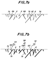
- Fig. 7(a) When the machined surface 4 is exposed to the halogen-based corrosive gas, there is a tendency that as shown in Fig. 7(a), corrosion proceeds to extend tips of microcracks 7A, for example, as shown by 8A, 8B, 8C and the microcracks 7A are combined. It is considered that as shown in Fig. 7(b), particles 9A, 9B and 9C are consequently peeled off from the machined surface, so that new pits 12A, 12B and 12C are formed.
- Fig. 1 is compared with Fig. 2, it is considered that corrosion easily proceeds through combining of such microcracks and so on, from acute edges of the machined surfaces of the grains and their vicinities as starting points.
- the annealing temperature of the machined body depends upon the sintering temperature of the sintered body to be machined, but the annealing temperature must be not less than a temperature at which the material transfer starts inside and at the surfaces of the grains exposed to the machined surface of the machined body.
- the above annealing temperature is set preferably at not less than (To - 300)°C, more preferably at not less than (To - 200)°C in which To is the sintering temperature of the sintered body.
- the annealing temperature is set at not more than To, decrease in the dimensional precision of the ceramic parts due to dimensional shrinkage of the ceramic parts is small, and the center line depth Rp in a roughness curve does not excessively increase. From this point of view, it is more preferable that the annealing temperature is set at not more than (To - 100)°C. In the thermal treatment, only the surface of the machined body may be annealed by irradiation with laser beam.
- the present inventors ground a dense alumina sintered body, and observed it with an electron microscope. As shown in Fig. 1, acute edges are indeed seen at the machined surfaces of the grains, but microcracks themselves are hardly seen. However, when the machined body is heated at 1200°C, fine cracks and numerous grain boundaries come to appear. The reason is considered that the microcracks slightly grow and are visualized or cracks are formed by residual stress at the machined surface.
- the radius of curvature of the edge of the machined surface of the grain exposed to the machined surface of the machined body is particularly preferably not less than 0.1 ⁇ m.
- the upper limit for this radius of curvature is practically 2 ⁇ m.
- the average surface roughness (Ra) of the machined surface of the ceramic part is particularly preferably not more than 1 ⁇ m. By so setting, corrosion resistance against the halogen-based corrosive gas tends to be further enhanced. In addition, it is preferable to set the center line depth Rp in the roughness curve of the machined surface of the ceramic part is not more than 1.5 ⁇ m. By so setting, the progress of the microcracks from the pits can be suppressed.
- the center line depth Rp in the roughness curve will be explained.
- a roughness curve is obtained with respect to a machined surface of a machined body, and a center line of this roughness curve is determined.
- the center line is a straight line which is in parallel to an average line of the roughness curve and which makes equal areas of zones on opposite sides of the center line which zones are each defined by the roughness curve and the center line.
- the center line depth in the roughness curve is a distance from the center line to such a highest vertex of a section cut from the roughness curve over a standard length as measured from the center line within that section.
- the entire ceramic part according to the present invention needs not be made of a ceramic material containing aluminum, at least a portion of the ceramic part which is to contact the halogen-based corrosive gas is preferably made of such a ceramic material containing aluminum.
- the ceramic parts to which the present invention is applicable mention may be made of devices such as a ceramic heater in which a resistive heating element is buried in a substrate made of a ceramic material containing aluminum, a ceramic electrostatic chuck in which an electrostatically chucking electrode is buried in a substrate, an electrostatic chuck-provided heater in which a resistive heating element and an electrostatically chucking electrode are buried in a substrate, and a high frequency wave generating electrode device in which a plasma-generating electrode is buried in a substrate.
- devices such as a ceramic heater in which a resistive heating element is buried in a substrate made of a ceramic material containing aluminum, a ceramic electrostatic chuck in which an electrostatically chucking electrode is buried in a substrate, an electrostatic chuck-provided heater in which a resistive heating element and an electrostatically chucking electrode are buried in a substrate, and a high frequency wave generating electrode device in which a plasma-generating electrode is buried in a substrate.
- the ceramic parts according to the present invention may be applied to dummy wafers, shadow rings, tubes for generating high frequency plasma, domes for generating high frequency plasma, high frequency wave permeable windows, infrared ray permeable windows, lift pins for supporting semiconductor wafers, shower plates, etc.
- the machined body is annealed without mirror polishing the machined surface thereof. In this case, generation of particles can be suppressed without performing expensive mirror polishing.
- a mixture was obtained by adding 60 parts by weight of water into 100 parts by weight of alumina powder having the average particle diameter of 0.5 ⁇ m, and a slurry was obtained by mixing in a trommel for 3 hours. Such an amount of polyvinyl alcohol as corresponding to 2 parts by weight was added into this slurry, and spherical granulated particles were formed by a spray dryer.
- Granulated particles were charged into a rubber mold, and a molded body was obtained by molding under pressure of 3 tons/cm 2 according to cold isostatic press.
- the thus obtained molded body was heated up to the maximum temperature of 500°C at a heating rate of 20°C/hour in an atmospheric atmosphere, and held at 500°C for 15 hours.
- a sintered body was obtained by holding the dewaxed body at 1600°C for 3 hours in atmosphere.
- the Ra of the thus obtained sintered bodies ranged from 1.4 to 2.7 ⁇ m, and the Rp thereof ranged from 3.8 to 9.6 ⁇ m.
- the sintered body was ground by using a diamond rotary grinding stone, thereby obtaining a machined body having a planar shape.
- porosity was measured according to the Archimedes method, and the average surface roughness (Ra) and the average surface roughness Rp in the roughness curve were measured by using a surface roughness meter.
- the machined body was placed as a test piece inside a chamber for a semiconductor-producing apparatus, plasma was generated at a temperature of 400°C by using NF 3 gas, and the test piece was exposed to plasma for 10 hours.
- a mirror-polished semiconductor wafer was pressed against the test piece having been exposed to the plasma, and a load of 50 g/cm 2 was applied thereto.
- An amount of particles attached to the mirror-polished surface of this semiconductor wafer was measured by using a wafer dust inspector popular in the semiconductor factories.
- the amount of the particles detected from the semiconductor wafer is not more than 30/cm 2 , the semiconductor does not empirically become defective owing to particles. Accordingly, the machined bodies produced not more than 30 particles/cm 2 were judged acceptable. Further, the surface of each machined body before and after exposure to the NF 3 was observed with an electron microscope, and results are shown in Figs. 1 and 2.
- the porosity of the machined body was 0.05%, and the Ra and the Rp were 0.4 ⁇ m and 0.7 ⁇ m, respectively.
- the radius of curvature of the edge of the machined surface of each of the particles was 0.04 ⁇ m.
- the amount of the particles was 120/cm 2 .
- a machined body in Comparative Example 1 was heated up to 1200°C at a heating rate of 200°C/hour in an atmospheric atmosphere, and held at 1200°C for 3 hours, thereby obtaining a ceramic part.
- the porosity of the machined body was 0.05%, and the Ra and the Rp were 0.4 ⁇ m and 0.7 ⁇ m, respectively.
- the radius of curvature of the edge of the machined surface of each of the grains was 0.07 ⁇ m.
- the amount of the particles was 60/cm 2 . Observation of the surface of the ceramic part with the electron microscope enabled fine cracks and numerous particles to be seen.
- a machined body was heated up to 1300°C at a heating rate of 200°C/hour in an atmospheric atmosphere, and held at 1300°C for 3 hours, thereby obtaining a ceramic part.
- the porosity of the ceramic part was 0.05%, and the Ra and the Rp were 0.4 ⁇ m and 0.9 ⁇ m, respectively.
- the radius of curvature of the edge of the machined surface of each of the grains was 0.13 ⁇ m.
- the amount of the particles was 30/cm 2 .
- An electron micrograph of the ceramic tissue of the machined surface of the ceramic part is shown in Fig. 5. As is seen from Fig. 5, the edges of the grains were made round.
- a machined body in Comparative Example 1 was heated up to 1500°C at a heating rate of 200°C/hour in an atmospheric atmosphere, and held at 1500°C for 3 hours, thereby obtaining a ceramic part.
- the porosity of the machined body was 0.05%, and the Ra and the Rp were 0.4 ⁇ m and 1.1 ⁇ m, respectively.
- the radius of curvature of the edge of the machined surface of each of the grains was 0.8 ⁇ m.
- the amount of the particles was 10/cm 2 .
- An electron micrograph of the machined surface of the ceramic part is shown in Fig. 3.
- Fig. 4 is shown an electron micrograph of the machined surface of the ceramic part after exposure to NF 3 gas.
- a machined body in Comparative Example 1 was heated up to 1600°C at a heating rate of 200°C/hour in an atmospheric atmosphere, and held at 1600°C for 3 hours, thereby obtaining a ceramic part.
- the porosity of the machined body was 0.05%, and the Ra and the Rp were 0.4 ⁇ m and 1.4 ⁇ m, respectively.
- the radius of curvature of the edge of the machined surface of each of the grains was 1.3 ⁇ m.
- the amount of the particles was 5/cm 2 .
- a machined body in Comparative Example 1 was heated up to 1700°C at a heating rate of 200°C/hour in an atmospheric atmosphere, and held at 1700°C for 3 hours, thereby obtaining a ceramic part.
- the porosity of the machined body was 0.04%, and the Ra was 0.4 ⁇ m, whereas the Rp increased to 3.5 ⁇ m.
- the radius of curvature of the edge of the machined surface of each of the grains was 1.9 ⁇ m.
- the amount of the particles was 4/cm 2 .
- Y 2 O 3 powder 0.1 % by weight, was added into aluminum nitride powder having the average particle diameter of 0.5 ⁇ m, the content of oxygen of not more than 1.3 % by weight, and the content of cation impurities of not more than 0.3 % by weight.
- the mixed powders were wet mixed in a trommel with use of an organic solvent for not less than 3 hours, thereby obtaining a slurry.
- the resulting slurry was granulated into granulated powder by using a spray dryer.
- a molded body was obtained by press molding the granulated powder under molding pressure of 200 kg/cm 2 , and the molded body was fired by hot press at a firing temperature of 1800°C under a molding pressure of 200 kg/cm 2 , thereby obtaining a sintered body.
- the Ra of the thus obtained sintered bodies 1 ranged from 1.2 to 2.5 ⁇ m, whereas the Rp thereof ranged from 1.9 to 5.6 ⁇ m.
- the sintered body was ground by using a diamond rotary grinding stone, thereby obtaining a machined body having a planar shape.
- porosity was measured according to the Archimedes method, and the average surface rouguhness (Ra) and the center line depth Rp in the roughness curve were measured by using the surface roughness meter.
- an amount of particles was also measured after the exposure to NF 3 gas.
- the porosity of the machined body was 0.01%, and the Ra and the Rp were 0.1 ⁇ m and 0.4 ⁇ m, respectively.
- the radius of curvature of the edge of the machined surface of each of the grains was 0.03 ⁇ m.
- the amount of the particles was 210/cm 2 .
- a machined body in Comparative Example 1 was heated up to 1700°C at a heating rate of 200°C/hour in an atmospheric atmosphere, and held at 1700°C for 4 hours, thereby obtaining a ceramic part.
- the porosity of the machined body was 0.01%, and the Ra and the Rp were 0.2 ⁇ m and 0.6 ⁇ m, respectively.
- the radius of curvature of the edge of the machined surface of each of the grains was 0.2 ⁇ m.
- the amount of the particles was 10/cm 2 .
- the generation of the particles from the ceramic parts upon exposure to the corrosive gas can be prevented by appropriately treating the ceramic parts during the production.
Landscapes
- Chemical & Material Sciences (AREA)
- Engineering & Computer Science (AREA)
- Ceramic Engineering (AREA)
- Materials Engineering (AREA)
- Structural Engineering (AREA)
- Organic Chemistry (AREA)
- Drying Of Semiconductors (AREA)
- Compositions Of Oxide Ceramics (AREA)
- Ceramic Products (AREA)
- Container, Conveyance, Adherence, Positioning, Of Wafer (AREA)
- Preventing Corrosion Or Incrustation Of Metals (AREA)
- Grinding And Polishing Of Tertiary Curved Surfaces And Surfaces With Complex Shapes (AREA)
Applications Claiming Priority (2)
| Application Number | Priority Date | Filing Date | Title |
|---|---|---|---|
| JP33910396A JPH10167859A (ja) | 1996-12-05 | 1996-12-05 | セラミックス部品およびその製造方法 |
| JP339103/96 | 1996-12-05 |
Publications (3)
| Publication Number | Publication Date |
|---|---|
| EP0846667A2 true EP0846667A2 (de) | 1998-06-10 |
| EP0846667A3 EP0846667A3 (de) | 1999-01-27 |
| EP0846667B1 EP0846667B1 (de) | 2006-03-15 |
Family
ID=18324296
Family Applications (1)
| Application Number | Title | Priority Date | Filing Date |
|---|---|---|---|
| EP97309690A Expired - Lifetime EP0846667B1 (de) | 1996-12-05 | 1997-12-02 | Keramikteile und Verfahren zu ihren Herstellung |
Country Status (6)
| Country | Link |
|---|---|
| US (1) | US6258440B1 (de) |
| EP (1) | EP0846667B1 (de) |
| JP (1) | JPH10167859A (de) |
| KR (1) | KR100259572B1 (de) |
| DE (1) | DE69735467T2 (de) |
| TW (1) | TW406293B (de) |
Cited By (1)
| Publication number | Priority date | Publication date | Assignee | Title |
|---|---|---|---|---|
| WO2007145505A1 (en) * | 2006-06-12 | 2007-12-21 | Xycarb Ceramics B.V. | Method for manufacturing a device for supporting a substrate during the manufacture of semiconductor components, as well as such a device |
Families Citing this family (22)
| Publication number | Priority date | Publication date | Assignee | Title |
|---|---|---|---|---|
| TW579372B (en) * | 1998-07-29 | 2004-03-11 | Sumitomo Chemical Co | Process for producing alumina sintered body |
| JP2000109989A (ja) * | 1998-10-05 | 2000-04-18 | Tokai Carbon Co Ltd | プラズマ処理装置の内壁保護部材 |
| JP4166386B2 (ja) * | 1999-09-30 | 2008-10-15 | 日本碍子株式会社 | 耐蝕性部材およびその製造方法 |
| JP2001097790A (ja) * | 1999-09-30 | 2001-04-10 | Ngk Insulators Ltd | 耐蝕性部材およびその製造方法 |
| JP2003533010A (ja) * | 1999-09-30 | 2003-11-05 | ラム リサーチ コーポレーション | 前処理を行なったガス整流板 |
| US20030062358A1 (en) * | 2000-07-19 | 2003-04-03 | Atsushi Ito | Semiconductor manufacturing/testing ceramic heater |
| WO2002007195A1 (fr) * | 2000-07-19 | 2002-01-24 | Ibiden Co., Ltd. | Dispositif chauffant ceramique pour la fabrication/verification de semi-conducteurs, son procede de fabrication, et son systeme de fabrication |
| US20040035846A1 (en) * | 2000-09-13 | 2004-02-26 | Yasuji Hiramatsu | Ceramic heater for semiconductor manufacturing and inspecting equipment |
| JP2003288766A (ja) * | 2002-03-28 | 2003-10-10 | Kyocera Corp | 磁気ディスク基板用保持部材及びその製造方法 |
| JP3864958B2 (ja) * | 2004-02-02 | 2007-01-10 | 東陶機器株式会社 | 耐プラズマ性を有する半導体製造装置用部材およびその作製方法 |
| US20050274396A1 (en) * | 2004-06-09 | 2005-12-15 | Hong Shih | Methods for wet cleaning quartz surfaces of components for plasma processing chambers |
| US20050284573A1 (en) * | 2004-06-24 | 2005-12-29 | Egley Fred D | Bare aluminum baffles for resist stripping chambers |
| US20060228889A1 (en) * | 2005-03-31 | 2006-10-12 | Edelberg Erik A | Methods of removing resist from substrates in resist stripping chambers |
| US8617672B2 (en) * | 2005-07-13 | 2013-12-31 | Applied Materials, Inc. | Localized surface annealing of components for substrate processing chambers |
| JP6049056B2 (ja) * | 2012-08-23 | 2016-12-21 | 神島化学工業株式会社 | 光学用セラミックスとその製造方法 |
| JP6017895B2 (ja) * | 2012-09-03 | 2016-11-02 | 日本特殊陶業株式会社 | アルミナ質焼結体の製造方法、真空チャックの製造方法、及び静電チャックの製造方法 |
| BE1021335B1 (fr) * | 2014-07-16 | 2015-11-03 | Magotteaux International S.A. | Grains ceramiques et procede pour leur production. |
| JP6782157B2 (ja) * | 2016-12-20 | 2020-11-11 | 日本特殊陶業株式会社 | 静電チャック |
| JP2018172241A (ja) * | 2017-03-31 | 2018-11-08 | 島根県 | サイアロンセラミックス及びその製造方法 |
| JP6914335B2 (ja) * | 2017-07-28 | 2021-08-04 | 京セラ株式会社 | プラズマ処理装置用部材 |
| JP7742332B2 (ja) * | 2022-04-15 | 2025-09-19 | 日本特殊陶業株式会社 | 保持部材および静電チャック |
| CN117447191A (zh) * | 2023-11-07 | 2024-01-26 | 上海卡贝尼精密陶瓷有限公司 | 半导体设备腔体高纯氧化铝陶瓷产品机加工后二次高温烧结方法 |
Family Cites Families (6)
| Publication number | Priority date | Publication date | Assignee | Title |
|---|---|---|---|---|
| US3791861A (en) * | 1971-04-16 | 1974-02-12 | Bell Telephone Labor Inc | Method for producing thin film circuits on high purity alumina substrates |
| US4681538A (en) * | 1984-04-23 | 1987-07-21 | Johnson & Johnson Dental Products, Company | Crystalline alumina composites |
| JPH03228502A (ja) * | 1990-01-30 | 1991-10-09 | Mitsubishi Materials Corp | アルミナ基セラミックス切削工具の製造法 |
| JPH0426546A (ja) * | 1990-05-18 | 1992-01-29 | Ngk Insulators Ltd | 高耐酸性の高強度ジルコニアセラミックスの製造方法 |
| JPH05305561A (ja) * | 1992-05-01 | 1993-11-19 | Sumitomo Electric Ind Ltd | 窒化ケイ素系セラミックスの研削加工方法及びその加工製品 |
| KR950702511A (ko) * | 1993-06-01 | 1995-07-29 | 구라우치 노리타카 | 세라믹 소결체 및 이의 표면 가공방법(Ceramic sintered body and method of processing surface of body) |
-
1996
- 1996-12-05 JP JP33910396A patent/JPH10167859A/ja active Pending
-
1997
- 1997-12-01 TW TW086118027A patent/TW406293B/zh not_active IP Right Cessation
- 1997-12-02 EP EP97309690A patent/EP0846667B1/de not_active Expired - Lifetime
- 1997-12-02 DE DE69735467T patent/DE69735467T2/de not_active Expired - Lifetime
- 1997-12-02 US US08/982,346 patent/US6258440B1/en not_active Expired - Fee Related
- 1997-12-04 KR KR1019970065874A patent/KR100259572B1/ko not_active Expired - Fee Related
Cited By (1)
| Publication number | Priority date | Publication date | Assignee | Title |
|---|---|---|---|---|
| WO2007145505A1 (en) * | 2006-06-12 | 2007-12-21 | Xycarb Ceramics B.V. | Method for manufacturing a device for supporting a substrate during the manufacture of semiconductor components, as well as such a device |
Also Published As
| Publication number | Publication date |
|---|---|
| DE69735467D1 (de) | 2006-05-11 |
| US6258440B1 (en) | 2001-07-10 |
| KR19980063777A (ko) | 1998-10-07 |
| TW406293B (en) | 2000-09-21 |
| DE69735467T2 (de) | 2006-11-16 |
| KR100259572B1 (ko) | 2000-06-15 |
| EP0846667B1 (de) | 2006-03-15 |
| EP0846667A3 (de) | 1999-01-27 |
| JPH10167859A (ja) | 1998-06-23 |
Similar Documents
| Publication | Publication Date | Title |
|---|---|---|
| US6258440B1 (en) | Ceramic parts and a producing process thereof | |
| JP4213790B2 (ja) | 耐プラズマ部材およびそれを用いたプラズマ処理装置 | |
| JP3362113B2 (ja) | 耐蝕性部材、ウエハー設置部材および耐蝕性部材の製造方法 | |
| TWI769013B (zh) | 包含鋁酸鎂尖晶石之陶瓷燒結體 | |
| KR102818334B1 (ko) | 에칭 적용을 위한 제어된 다공성 산화이트륨 | |
| WO2001025167A1 (en) | Process for cleaning ceramic articles | |
| KR100953707B1 (ko) | 반도체 프로세싱 부품 및 이를 사용하는 반도체 제조방법 | |
| KR100575393B1 (ko) | 세라믹 제품의 세정방법 | |
| JP3555442B2 (ja) | プラズマ耐食性に優れたアルミナセラミックス材料およびその製造方法 | |
| JP3527839B2 (ja) | 半導体素子製造装置用部材 | |
| US6063514A (en) | Gas-tight article and a producing process thereof | |
| JP2001102365A (ja) | 真空容器及びその製造方法 | |
| JP2008156160A (ja) | 耐食性部材およびその製造方法 | |
| JP2000103689A (ja) | アルミナ質焼結体およびその製造方法、並びに耐プラズマ部材 | |
| JP3623054B2 (ja) | プラズマプロセス装置用部材 | |
| JPH11209182A (ja) | プラズマ耐食部材 | |
| JPH0881258A (ja) | アルミナセラミックス焼結体 | |
| Kobayashi et al. | Effect of quartz grain size on elastic and thermal expansion properties of porcelain | |
| JP3456915B2 (ja) | 半導体製造装置用部材 | |
| JP3362062B2 (ja) | 半導体製造装置用セラミック部材及びその製造方法 | |
| JP7420600B2 (ja) | 耐食性部材 | |
| JP2000109989A (ja) | プラズマ処理装置の内壁保護部材 | |
| KR100778274B1 (ko) | 산화 이트늄 소결체 및 그 제조 방법 | |
| JPH1160356A (ja) | 窒化アルミニウム複合基材及びこれを用いた窒化アルミニウム複合発熱体、窒化アルミニウム複合静電チャック、窒化アルミニウム複合ヒータ付静電チャック | |
| JP2005022971A (ja) | プラズマプロセス装置用部材 |
Legal Events
| Date | Code | Title | Description |
|---|---|---|---|
| PUAI | Public reference made under article 153(3) epc to a published international application that has entered the european phase |
Free format text: ORIGINAL CODE: 0009012 |
|
| AK | Designated contracting states |
Kind code of ref document: A2 Designated state(s): DE FR GB |
|
| AX | Request for extension of the european patent |
Free format text: AL;LT;LV;MK;RO;SI |
|
| PUAL | Search report despatched |
Free format text: ORIGINAL CODE: 0009013 |
|
| AK | Designated contracting states |
Kind code of ref document: A3 Designated state(s): AT BE CH DE DK ES FI FR GB GR IE IT LI LU MC NL PT SE |
|
| AX | Request for extension of the european patent |
Free format text: AL;LT;LV;MK;RO;SI |
|
| 17P | Request for examination filed |
Effective date: 19990617 |
|
| AKX | Designation fees paid |
Free format text: DE FR GB |
|
| 17Q | First examination report despatched |
Effective date: 20030602 |
|
| GRAP | Despatch of communication of intention to grant a patent |
Free format text: ORIGINAL CODE: EPIDOSNIGR1 |
|
| RIC1 | Information provided on ipc code assigned before grant |
Ipc: 7C 04B 41/53 A |
|
| GRAS | Grant fee paid |
Free format text: ORIGINAL CODE: EPIDOSNIGR3 |
|
| GRAA | (expected) grant |
Free format text: ORIGINAL CODE: 0009210 |
|
| AK | Designated contracting states |
Kind code of ref document: B1 Designated state(s): DE FR GB |
|
| REG | Reference to a national code |
Ref country code: GB Ref legal event code: FG4D |
|
| REF | Corresponds to: |
Ref document number: 69735467 Country of ref document: DE Date of ref document: 20060511 Kind code of ref document: P |
|
| ET | Fr: translation filed | ||
| PLBE | No opposition filed within time limit |
Free format text: ORIGINAL CODE: 0009261 |
|
| STAA | Information on the status of an ep patent application or granted ep patent |
Free format text: STATUS: NO OPPOSITION FILED WITHIN TIME LIMIT |
|
| 26N | No opposition filed |
Effective date: 20061218 |
|
| PGFP | Annual fee paid to national office [announced via postgrant information from national office to epo] |
Ref country code: GB Payment date: 20101123 Year of fee payment: 14 |
|
| PGFP | Annual fee paid to national office [announced via postgrant information from national office to epo] |
Ref country code: FR Payment date: 20111205 Year of fee payment: 15 |
|
| PGFP | Annual fee paid to national office [announced via postgrant information from national office to epo] |
Ref country code: DE Payment date: 20111230 Year of fee payment: 15 |
|
| GBPC | Gb: european patent ceased through non-payment of renewal fee |
Effective date: 20121202 |
|
| REG | Reference to a national code |
Ref country code: FR Ref legal event code: ST Effective date: 20130830 |
|
| REG | Reference to a national code |
Ref country code: DE Ref legal event code: R119 Ref document number: 69735467 Country of ref document: DE Effective date: 20130702 |
|
| PG25 | Lapsed in a contracting state [announced via postgrant information from national office to epo] |
Ref country code: DE Free format text: LAPSE BECAUSE OF NON-PAYMENT OF DUE FEES Effective date: 20130702 |
|
| PG25 | Lapsed in a contracting state [announced via postgrant information from national office to epo] |
Ref country code: GB Free format text: LAPSE BECAUSE OF NON-PAYMENT OF DUE FEES Effective date: 20121202 Ref country code: FR Free format text: LAPSE BECAUSE OF NON-PAYMENT OF DUE FEES Effective date: 20130102 |