EP0844081A1 - Verfahren und Vorrichtung zum Bestäuben von Produkten, insbesondere Druckprodukten - Google Patents
Verfahren und Vorrichtung zum Bestäuben von Produkten, insbesondere Druckprodukten Download PDFInfo
- Publication number
- EP0844081A1 EP0844081A1 EP97116338A EP97116338A EP0844081A1 EP 0844081 A1 EP0844081 A1 EP 0844081A1 EP 97116338 A EP97116338 A EP 97116338A EP 97116338 A EP97116338 A EP 97116338A EP 0844081 A1 EP0844081 A1 EP 0844081A1
- Authority
- EP
- European Patent Office
- Prior art keywords
- products
- powder
- gas
- suction
- transport gas
- Prior art date
- Legal status (The legal status is an assumption and is not a legal conclusion. Google has not performed a legal analysis and makes no representation as to the accuracy of the status listed.)
- Granted
Links
Images


Classifications
-
- B—PERFORMING OPERATIONS; TRANSPORTING
- B05—SPRAYING OR ATOMISING IN GENERAL; APPLYING FLUENT MATERIALS TO SURFACES, IN GENERAL
- B05B—SPRAYING APPARATUS; ATOMISING APPARATUS; NOZZLES
- B05B7/00—Spraying apparatus for discharge of liquids or other fluent materials from two or more sources, e.g. of liquid and air, of powder and gas
- B05B7/14—Spraying apparatus for discharge of liquids or other fluent materials from two or more sources, e.g. of liquid and air, of powder and gas designed for spraying particulate materials
- B05B7/1404—Arrangements for supplying particulate material
-
- B—PERFORMING OPERATIONS; TRANSPORTING
- B05—SPRAYING OR ATOMISING IN GENERAL; APPLYING FLUENT MATERIALS TO SURFACES, IN GENERAL
- B05B—SPRAYING APPARATUS; ATOMISING APPARATUS; NOZZLES
- B05B7/00—Spraying apparatus for discharge of liquids or other fluent materials from two or more sources, e.g. of liquid and air, of powder and gas
- B05B7/0075—Nozzle arrangements in gas streams
-
- B—PERFORMING OPERATIONS; TRANSPORTING
- B41—PRINTING; LINING MACHINES; TYPEWRITERS; STAMPS
- B41F—PRINTING MACHINES OR PRESSES
- B41F23/00—Devices for treating the surfaces of sheets, webs, or other articles in connection with printing
- B41F23/04—Devices for treating the surfaces of sheets, webs, or other articles in connection with printing by heat drying, by cooling, by applying powders
- B41F23/06—Powdering devices, e.g. for preventing set-off
Definitions
- the invention relates to a method for dusting Products, especially printed products, according to the generic term of claim 1 and a device for performing such a method according to the preamble of claim 10.
- the products are not rigid Products, e.g. Print sheets, so generate from the dispensing nozzles emitted powder gas jets a transverse channel in the product. This is with a view to flutter-free Adverse of the products. Through the sharp pressing of the powder gas jets to the surface of the pollinating products also get unstable flow conditions.
- Another disadvantage of the known arrangement is that the reflected air jets are one larger subset of the powder from the surface of the to carry away pollinating products.
- a method and specified a device for dusting products which have a better transfer efficiency of powder from the powder gas flow onto the products is guaranteed.
- this object is achieved by a method with the features specified in claim 1 or a device with the features specified in claim 10.
- the powder gas flow proportions which from the surface of the printed products be reflected by a transport gas stream fed back to the product surface.
- This transport gas stream is rubbed against the product surface and is essentially laminar.
- Claim 7 and 8 achieved that such powder particles after a first impact on the product surface not got stuck on this, again against the Product surface. This is done according to Claim 7 by a counter to the direction of conveyance Products current transport gas flow, according to the training of the invention according to claim 8 by a gentle, to the conveying direction of the products in the same direction transport gas flow.
- the powder gas in the part of the transport gas stream adjacent to the conveying surface fed in which is also possible extensive powder transfer to the product surfaces is an advantage.
- the arrangement according to claim 14 is possible with regard to intensive initial contact of the powder gas with the product surface advantageous.
- the powder gas manifold is in the slipstream of hub sections of Blower wheels, does not disturb the transport gas flow essential, but you only have small flow paths from the powder gas distributor pipe to the discharge ends of the Dispensing nozzles.
- powder gas escapes not in the area, even if the powder gas release is not strictly synchronized with the products to be pollinated is controlled at the powder gas discharge nozzles.
- this is done automatically an adaptation of the transport gas flow to the conveying speed of the products.
- the development of the invention according to claim 24 ensures a transverse to the product conveying direction Direction of uniform suction of gas, which is not contains used powder particles.
- the development of the invention is according to claim 25 advantageous in that the amount of against the Products escaping transport gas and possibly sealing gas according to the respective funding conditions for the Can set products. So you have e.g. for printed products take into account that these are different from paper Basis weight can be made, and around always the same in the area of the pollination device To have funding, you have to have printed products high basis weight with a little less transport gas and Apply sealing gas as products with a low basis weight, if despite the different weights of the Products in the same position in front of the powder gas dispenser wants to guarantee. Powder separation devices, e.g. Powder separation cyclones then work with the best Efficiency when the total gas flow through it does not change.
- the development of the invention according Claim 25 allows the transport gas stream and possibly Varying the sealing gas flow by controlling it in opposite directions the secondary air opening but the total gas flow that the Separation unit is fed to keep constant.
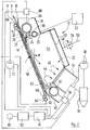
- a Powder gas manifold 20 In extension of the hubs of the impellers 16 is a Powder gas manifold 20 arranged, which with the output a powder gas generator 22 is connected. Details the construction of such a powder gas generator can can be taken from DE 38 19 203 A1, on which in this regard Reference is made.
- the powder gas distributor pipe 20 is perpendicular to the plane of the drawing spaced and aligned one behind the other A plurality of powder gas discharge nozzles 24 that are tubular and extend into the vicinity of the funding level 10.
- the dispensing nozzles 24 and the powder gas manifold 20 together form a rake-like structure, which is flowed through by the transport gas stream 18.
- the dispensing nozzles 24 each give under working conditions a powder gas bundle 26, which powder particles distributed in air having.
- the powder gas tufts 26 are against Surface of the printed sheet directed. That from the product surface flowing away, containing less powder particles Powder gas becomes tangential through the transport gas stream 18 Direction along the conveyor plane 10 in the drawing moved downwards so that more powder particles continuously against the sticky surface of the printed sheets to be dusted be performed.
- the delivery chute 14 for the transport gas flow 16 at an angle w against the conveying plane 10 is inclined, the amounts in the embodiment contemplated here approximately 22 o.
- the height of the discharge chute 14 is matched to the length of a window 28, which is provided in a wall 30 of a housing 32 facing the conveying plane 10, in accordance with the angle w.
- the housing 32 carries one at its upstream end Suction shaft 34, via a powder separation cyclone 36 is connected to the inlet of a suction fan 38.
- the axis of the suction shaft 34 closes with the conveying plane 10 an angle that is the same amount is like the angle w, but the opposite sign Has.
- a sealing air shaft is located below the suction shaft 34 40 arranged in which successively perpendicular to the plane of the drawing a plurality of impellers 42 are arranged is. These generate a sealing air flow 44 which the mixture of transport gas and depleted powder gas in redirects the suction shaft 34 set to the conveying level 10, as shown at 46.
- the wall surface of the housing remote from the conveying plane 10 32 is formed by a microporous plate 48, behind which there is a compressed air box 50.
- a plate 52 which also is made of microporous material, and behind which is also a compressed air box.
- the above the boundary wall of the housing to be thought of in the drawing plane 32 is designed analogously.
- the compressed air box 50 and the other compressed air boxes are via a pressure regulator 54 connected to a compressed air line 56. To this Way constantly emerges from the surfaces of the plates 48, 52 air at low speed, which prevents is that powder particles accumulate on the plates 48, 52.
- a guide plate 58 is located somewhat behind the conveyor level 10 arranged, which has larger dimensions than the window 28, and at the upstream end with an inlet slope 60 and at the downstream end with an outlet slope 62 is provided. These bevels work with the press sheet gripping bars together.
- a compressed air distribution pipe 64 arranged which is a plurality perpendicular to Drawing level successively and in the wedge-shaped Gap-pointing compressed air discharge nozzles 66.
- the guide plate 58 serves on the one hand as a support for the Sheet against the incoming powder gas and transport gas.
- the guide plate 58 also serves as a cover for the window 28 on which powder gas and transport gas are retained and are directed back to the suction shaft 34, if there is no printed sheet in front of window 28, or only part of a sheet is there.
- the compressed air manifolds 64 and 70 are with the outlet a blower 72 connected by a blower control unit 74 ago is controlled.
- the latter controls furthermore the suction fan 38 and drive motors 76, 78, which drive the impellers 16 and 42, respectively.
- the blower control unit 74 operates in dependence from the output signal of a speed sensor 80, the one for the conveying speed of the printed sheet gripping bars provides proportional signal. It can this is a tachometer generator that works with a Sprocket works together, over which one the sheet-gripping bars carrying chain is running. The blower control unit Roughly speaking, 74 works in such a way that it Delivery capacity of the various fans increases when the Conveying speed of the products is increased, vice versa the flow rate of the blower decreases when the products be moved more slowly.
- a curve 82 is inserted, e.g. a constant for low conveyor speeds can set small base power of the blower, and a constant upper one for high conveyor speeds Blower performance can specify these areas by a proportional zone are connected.
- the amount of air from the sealing air shaft 40 sealing air emitted is significantly smaller than the amount of transport air discharged from the discharge chute 14, and the amounts of that from the compressed air manifolds 64, 68 released sealing air is again clear less than the amount of sealing air.
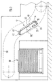
- Blower wheels 16 is in the discharge shaft 14 downstream of the powder gas discharge nozzles 24 now a discharge pipe 84 for transport gas arranged, which opposes a plurality at the angle w the conveying surface 10 employed discharge nozzles 86 for transport air having. Those emerging from the dispensing nozzles 86 Air jets together form one of the discharge ends of the Powder gas discharge nozzles 24 adjacent air flow 18.
- the two ends of the delivery tube 84 are over one controllable current regulator 88 with the output of the fan 72 connected.
- the current regulator 88 is controlled by the fan control 74 analogous to the control of the drive motor 76 of Figure 1.
- Dispensing tube 90 is provided for sealing air, which on average employed at the angle w against the conveying plane 10 Has discharge nozzles 92 for sealing air.
- the dispensing tube 90 has one end at both ends Current regulator 94 connected to the output of fan 72, the flow controller 94 through the fan controller 74 is controlled in a similar manner as the drive motor 78 in the exemplary embodiment according to FIG. 1.
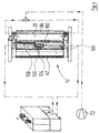
- FIG 3 is the course by the dashed line 96 the chains of the printed sheet conveying device carrying the grippers 6 shown.
- 98 denotes a sheet depositing station.
- a pollination box 12 is arranged in the ascending section of the funding path between the outlet of the multi-color press and the End of the printed sheet conveying path, which is above the filing station 98 lies.
- the blower wheels 16 providing transport gas are now arranged upstream of the powder gas distribution pipe 20, while the fan wheels generating the sealing gas flow 42 are located downstream of the pollination area.
- the fan wheels are designed and operated so that the transport gas stream 18 is smaller than the sealing air flow 44 due to the arrangement described, the transport gas stream runs 18 with a parallel to the product conveying direction Component, while the sealing gas flow one to Product conveying direction has opposite component.
- a suction tube 100 with a large diameter is provided between the powder gas partial tube 20 and the sealing air shaft 40.
- This is provided at its upper-most downstream Mantelinien with a plurality of suction openings 102 of illustration are reproduced half tilted by 90 ° upwards in Figures 4 and 5, in reality that is, in the mark levels of the figures are 4 and 5, namely on the left or top side of the suction pipe 100 there.
- the suction pipe 100 has in its from the conveying plane 10 area facing away from a central secondary air opening 104, by two oppositely symmetrical control spools 106 can be opened more or less. Moving the spool 106 may e.g. by a transverse actuating rod 108 take place.
- FIGS. 4 and 5 which is suitable for installation under particularly narrow spaces Conditions is determined, is compared to the embodiment according to Figure 3, the upstream set of impellers 16 replaced by a dispensing tube 84 as is was explained above with reference to FIG. 2.
- the fan wheels 42 are still provided.
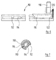
- FIG. 6 and 7 is a controllable slotted tube Play 110. This has a plurality along one Surface line successively and only by small Bridges 112 of separate slots 114, which are essentially one continuous axial slot of greater width pretend.
- the inside diameter of the outside diameter corresponds to the slotted tube 110.
- control spool 116 By turning the control spool 116 on the slotted tube 110 one can thus determine the effective extension of the slots 114 vary in the circumferential direction and so the flow cross section of the slot 114 change.
- Moving the Control spool 116 can e.g. by an actuator 118 take place with a pinion 120 in a from the spool 116 carried gear ring segment 122 engages.
- the slotted tube 110 can both be used to discharge a gas stream as well as for sucking in gas.
- both Applications have one in the longitudinal direction of the pipe, i.e. in Product conveying direction transverse direction uniform Gas delivery or gas intake, the strength of the Slits 114 passing current by twisting the Control spool 116 is adjustable.
Landscapes
- Engineering & Computer Science (AREA)
- Mechanical Engineering (AREA)
- Air Transport Of Granular Materials (AREA)
- Application Of Or Painting With Fluid Materials (AREA)
- Printing Methods (AREA)
- Electrostatic Spraying Apparatus (AREA)
- Confectionery (AREA)
Abstract
Description
- Figur 1:
- einen Längsschnitt durch eine Vorrichtung zum Bestäuben von Druckprodukten sowie ein Blockschaltbild von Ver- und Entsorgungseinrichtungen für diese Vorrichtung;
- Figur 2:
- eine ähnliche Schnittansicht wie Figur 1, in welcher eine abgewandelte Bestäubungsvorrichtung wiedergegeben ist;
- Figur 3:
- eine schematische Ansicht des auslaufseitigen Endabschnittes einer Mehrfarben-Druckmaschine, in welcher eine weiter abgewandelte Bestäubungsvorrichtung schematisch wiedergegeben ist;
- Figur 4:
- eine Aufsicht auf die Bestäubungsvorrichtung nach Figur 3 in vergrößertem Maßstabe nach Abnehmen einer Deckplatte, wobei zusätzlich Verund Entsorgungseinrichtungen gezeigt sind;
- Figur 5:
- eine Aufsicht ähnlich zu Figur 4, bei welcher jedoch ein größerer Darstellungsmaßstab gewählt ist und die Ver- und Endsorgungseinrichtungen weggelassen sind;
- Figur 6:
- eine seitliche Ansicht eines steuerbaren Schlitzrohres, welches zur Abgabe von Transportgas oder Sperrgas oder aber auch zum Absaugen von nicht verbrauchte Puderpartikel enthaltendem Gas verwendet werden kann; und
- Figur 7:
- einen transversalen Schnitt durch das in Figur gezeigte Schlitzrohr.
Claims (28)
- Verfahren zum Bestäuben von Produkten, insbesondere Druckprodukten, bei welchema) aus Puderpartikeln und einem Gas ein Pudergasstrom hergestellt wird; undb) der Pudergasstrom gegen die Oberfläche der längs einer Förderfläche bewegten Produkte gerichtet wird,
dadurch gekennzeichnet, daßc) ein Transportgasstrom mit zur Förderfläche der Produkte tangentialer Geschwindigkeitskomponente gegen die Oberfläche der Produkte gerichtet wird, wobei der Transportgasstrom den Pudergasstrom räumlich überlappt. - Verfahren nach Anspruch 1, dadurch gekennzeichnet, daß der Pudergasstrom und die Förderfläche der Produkte im wesentlichen einen rechten Winkel miteinander einschließen.
- Verfahren nach Anspruch 1 oder 2, dadurch gekennzeichnet, daß der Anstellwinkel zwischen dem Trägergasstrom und der Förderfläche der Produkte zwischen 5o und 60o, vorzugsweise zwischen 10o und 45o, nochmals vorzugsweise zwischen 15o und 25o beträgt.
- Verfahren nach einem der Ansprüche 1 bis 3, dadurch gekennzeichnet, daß die Größe des Transportgasstromes in Abhängigkeit von der Fördergeschwindigkeit der Produkte eingestellt wird.
- Verfahren nach einem der Ansprüche 1 bis 4, dadurch gekennzeichnet, daß der Überlappungsbereich zwischen Pudergasstrom und Transportgasstrom der Förderfläche der Produkte benachbart ist.
- Verfahren nach einem der Ansprüche 1 bis 5, dadurch gekennzeichnet, daß ein Sperrgasstrom mit zur Förderfläche der Produkte tangentialer Geschwindigkeitskomponente gegen die Oberfläche des Produkte gerichtet wird, welcher dem Transportgasstrom entgegengesetzt ist und welcher bezüglich des Pudergasstromes dem Transportgasstrom gegenüber liegt.
- Verfahren nach Anspruch 6, dadurch gekennzeichnet, daß der Transportgasstrom eine der Förderrichtung der Produkte entgegengesetzte tangentiale Komponente aufweist und größer ist als der Sperrgasstrom, der eine mit der Förderrichtung der Produkte gleichlaufende tangentiale Komponente hat.
- Verfahren nach Anspruch 6, dadurch gekennzeichnet, daß der Transportgasstrom eine mit der Förderrichtung der Produkte laufende tangentiale Komponente aufweist und kleiner ist als der Sperrgasstrom, der eine zur Förderrichtung der Produkte gegenläufige tangentiale Komponente hat.
- Verfahren nach einem der Ansprüche 1 bis 8, dadurch gekennzeichnet, daß Transportgas und ggf. Sperrgas aus einem Raumbereich abgesaugt werden, welcher in Förderrichtung der Produkte gesehen stromab des Überlappungsbereiches von Transportgasstrom und Pudergasstrom liegt.
- Vorrichtung zur Durchführung des Verfahrens nach einem der Ansprüche 1 bis 9, mit mindestens einer Pudergas-Abgabeeinrichtung (24), welche sich transversal zur Förderrichtung der Produkte erstreckt, vorzugsweise eine Mehrzahl in transversaler Richtung beabstandeter Abgabedüsen für Pudergas aufweist und die mit einem Pudergasgenerator (22) verbunden ist, dadurch gekennzeichnet, daß sie aufweist: eine Abgabeeinrichtung (16, 76; 72, 84-88) für Transportgas, welche sich in Breitenrichtung, transversal zur Förderrichtung der Produkte erstreckt und durch welche ein Transportgasstrom (18) mit zur Förderebene (10) der Produkte (8) tangentialer Komponente erzeugt wird, und ein die Pudergas-Abgabeeinrichtung (24) umgebendes Gehäuse (32), welches sich zwischen der Transportgas-Abgabeeinrichtung (16, 76; 72, 84-88) und einer Absaugeinrichtung (34; 100) erstreckt, wobei die Breitenrichtung der Absaugeinrichtung in zur Förderrichtung der Produkte transversaler Richtung verläuft und die Absaugeinrichtung (34; 100) mit einem Sauggebläse (38) in Verbindung steht; und daß die Wirkebene der Transportgas-Abgabeeinrichtung (16, 76; 72, 84-88 ) und die Wirkebene der Absaugeinrichtung (34; 100) eine zur Förderfläche (10) der Produkte tangentiale Komponente aufweisen.
- Vorrichtung nach Anspruch 10, dadurch gekennzeichnet, daß die Wirkebenen der Transportgas-Abgabeeinrichtung (16, 76; 72, 84-88 und der Absaugeinrichtung (34; 100) im wesentlichen entgegengesetzt gleichen Anstellwinkel (w) zur Förderfläche (10) der Produkte (8) aufweisen.
- Vorrichtung nach Anspruch 10 oder 11, dadurch gekennzeichnet, daß in der durch die Pudergas-Abgabeeinrichtung (24) vorgegebenen Wirkebene die Abgabeenden von Pudergas-Abgabedüsen (24) kleineren Abstand von der Förderfläche (10) der Produkte aufweisen als die Wirkebene der Transportgas-Abgabeeinrichtung (16, 76; 72, 84-88 ).
- Vorrichtung nach einem der Ansprüche 10 bis 12, dadurch gekennzeichnet, daß beabstandete Pudergas-Abgabedüsen (24) der Pudergas-Abgabeeinrichtung von einem Pudergas-Verteilerrohr (20) getragen sind, so daß man ein rechenähnliches Gebilde erhält, wobei die Enden der Zinken des Rechens durch die Enden der Abgabedüsen (24) gebildet sind und der Förderfläche (10) der Produkte benachbart sind, während das Pudergas-Verteilerrohr (20) von der Förderfläche (10) abliegt.
- Vorrichtung nach einem der Ansprüche 10 bis 13, dadurch gekennzeichnet, daß die Achsen der Pudergas-Abgabedüsen (24) senkrecht auf der Förderfläche (10) der Produkte stehen.
- Vorrichtung nach Anspruch 13 oder 14, dadurch gekennzeichnet, daß das Pudergas-Verteilerrohr (20) in Strömungsrichtung des Transportgases gesehen hinter Nabenabschnitten von Gebläserädern (16) angeordnet ist, welche in einem Transportgas-Abgabeschacht (14) in transversaler Richtung nebeneinander liegend angeordnet sind.
- Vorrichtung nach einem der Ansprüche 10 bis 15, dadurch gekennzeichnet, daß zwischen der Absaugeinrichtung (34; 100) und der Förderfläche (10) der Produkte eine Sperrlufteinrichtung (40 ; 90, 92) angeordnet ist, deren Breitenrichtung in zur Förderrichtung der Produkte transversaler Richtung verläuft und die durch ein Gebläse (42; 72) beaufschlagt wird.
- Vorrichtung nach einem der Ansprüche 10 bis 16, dadurch gekennzeichnet, daß Wände (48, 52) des Gehäuses (32), welches die Transportgas-Abgabeeinrichtung (16, 76; 72, 84-88 ) mit der Absaugeinrichtung (34; 100) verbindet, zumindest teilweise aus mikroporösem Material hergestellt sind und ihre Rückseite mit Druckluftkammern (50) in Verbindung steht.
- Vorrichtung nach einem der Ansprüche 10 bis 17, dadurch gekennzeichnet, daß sich zwischen der Transportgas-Abgabeeinrichtung (16, 76; 72, 84-88 ) und der Absaugeinrichtung (34; 100) ein Leitkörper (58) erstreckt, welcher die Förderfläche (10) vorgibt oder dieser benachbart ist und vor welchem die Produkte vorbeilaufen.
- Vorrichtung nach Anspruch 18, dadurch gekennzeichnet, daß der Leitkörper (58) zumindest bei seinem in Produktförderrichtung gesehen stromaufseitigen Ende, vorzugsweise auch bei seinem stromabseitigen Ende, mit einer Führungsschräge (60; 62) für Produktträger (6) versehen ist.
- Vorrichtung nach Anspruch 18 oder 19, dadurch gekennzeichnet, daß beim stromaufseitigen Ende des Leitkörpers (58) eine Luftabgabeeinrichtung (64, 66) vorgesehen ist, welche einen zur Transportgas-Abgabeeinrichtung (14) hin gerichteten, im wesentlichen parallel zum Leitkörper (58) verlaufenden und sich über die Breite der Absaugeinrichtung (34; 100) erstreckenden Dichtluftstrom erzeugt.
- Vorrichtung nach einem der Ansprüche 18 bis 20, dadurch gekennzeichnet, daß am stromabseitigen Ende des Leitkörpers (58) eine Luftabgabeeinrichtung (68, 70) vorgesehen ist, welche einen zur Absaugeinrichtung (34; 100) hin gerichteten, im wesentlichen parallel zum Leitkörper (58) verlaufenden, und sich über die Breite der Transportgas-Abgabeeinrichtung (16, 76; 72, 84-88 ) erstreckenden Dichtluftstrom erzeugt.
- Vorrichtung nach einem der Ansprüche 10 bis 21, dadurch gekennzeichnet, daß die verschiedenen Gebläse (16; 38; 42; 72) durch eine Steuereinheit (74) jeweils gemäß der Fördergeschwindigkeit der Produkte gesteuert werden, wozu die Steuereinheit (74) eingangsseitig mit einem Geschwindigkeitsfühler (80) verbunden ist, der mit der Produktfördereinrichtung zusammenarbeitet.
- Vorrichtung nach einem der Ansprüche 10 bis 22, dadurch gekennzeichnet, daß die Transportgas-Abgabeeinrichtung (72, 84 bis 88) und ggf. die Sperrgas-Abgabeeinrichtung (72, 90 bis 94) ein Abgaberohr (84; 90) aufweisen, welches von beiden Enden her mit Transportgas bzw. Sperrgasbeaufschlagt wird.
- Vorrichtung nach Anspruch 23 zur Durchführung des Verfahrens nach Anspruch 9, dadurch gekennzeichnet, daß die Absaugeinrichtung ein Absaugrohr (100) aufweist, welches an beiden Enden mit einem Sauggebläse verbunden ist.
- Vorrichtung nach einem der Ansprüche 10 bis 24 zur Durchführung des Verfahrens nach Anspruch 9, dadurch gekennzeichnet, daß die Absaugeinrichtung ein zur Förderrichtung der Produkte transversales Absaugrohr (100) aufweist, welches über eine Puderabtrenneinheit (36), insbesondere einen Puderabscheidezyklon mit dem Einlaß eines Sauggebläses (38) verbunden ist und daß das Absaugrohr (100) eine steuerbare Nebenluftöffnung (104) aufweist, über welches es mit der Umgebungsatmosphäre in Verbindung bringbar ist.
- Vorrichtung nach Anspruch 25, dadurch gekennzeichnet, daß die Nebenluftöffnung (104) symmetrisch zur Mitte des Absaugrohres (100) in einem von der Förderebene der Produkte abliegenden Wandbereich des Absaugrohres (100) vorgesehen ist.
- Vorrichtung nach Anspruch 26, dadurch gekennzeichnet, daß die Nebenluftöffnung (104) durch zwei zwangsweise in Rohr-Längsrichtung symmetrisch zur Mitte des Absaugrohres (100) bewegbare Steuerschieber (106) oder einen transversal zur Rohrlängsrichtung bewegbaren Steuerschieber (116) steuerbar ist.
- Vorrichtung nach einem der Ansprüche 10 bis 27, dadurch gekennzeichnet, daß ein zur Abgabe oder zum Ansaugen von Gas verwendetes Schlitzrohr (110) eine sich im wesentlichen über die gesamte axiale Länge ersteckende Öffnung (114) aufweist und auf der Außenfläche des Abgaberohres ein Steuerschieber (116) in Umfangsrichtung verschiebbar angeordnet ist.
Applications Claiming Priority (2)
| Application Number | Priority Date | Filing Date | Title |
|---|---|---|---|
| DE19648227 | 1996-11-21 | ||
| DE19648227A DE19648227A1 (de) | 1996-11-21 | 1996-11-21 | Verfahren und Vorrichtung zum Bestäuben von Produkten, insbesondere Druckprodukten |
Publications (2)
| Publication Number | Publication Date |
|---|---|
| EP0844081A1 true EP0844081A1 (de) | 1998-05-27 |
| EP0844081B1 EP0844081B1 (de) | 2003-08-27 |
Family
ID=7812365
Family Applications (1)
| Application Number | Title | Priority Date | Filing Date |
|---|---|---|---|
| EP97116338A Expired - Lifetime EP0844081B1 (de) | 1996-11-21 | 1997-09-19 | Verfahren und Vorrichtung zum Bestäuben von Produkten, insbesondere Druckprodukten |
Country Status (4)
| Country | Link |
|---|---|
| US (1) | US5931095A (de) |
| EP (1) | EP0844081B1 (de) |
| AT (1) | ATE248061T1 (de) |
| DE (2) | DE19648227A1 (de) |
Cited By (2)
| Publication number | Priority date | Publication date | Assignee | Title |
|---|---|---|---|---|
| EP1798034A3 (de) * | 2005-12-14 | 2010-04-28 | manroland AG | Druckmaschine, insbesondere Bogendruckmaschine |
| CN103786430A (zh) * | 2013-12-25 | 2014-05-14 | 陕西北人印刷机械有限责任公司 | 一种节能型热风干燥系统及方法 |
Families Citing this family (10)
| Publication number | Priority date | Publication date | Assignee | Title |
|---|---|---|---|---|
| DE19859246A1 (de) * | 1998-01-20 | 1999-07-22 | Koch Hans Peter | Bogenoffsetdruckverfahren und Bogenoffsetdruckmaschine |
| DE19826083B4 (de) * | 1998-06-12 | 2005-03-31 | Koenig & Bauer Ag | Puderabsaugung in Auslegern von Bogenrotationsdruckmaschinen |
| DE19937090B4 (de) * | 1998-08-10 | 2004-10-21 | Weitmann & Konrad Gmbh & Co Kg | Verfahren und Vorrichtung zum Bestäuben von bedruckten Bogen |
| DE19920391B4 (de) * | 1999-05-04 | 2009-12-03 | Koenig & Bauer Aktiengesellschaft | Verfahren und Vorrichtung zum Aufbringen von Puder auf Bedruckstoffe |
| DE10065265A1 (de) | 2000-12-29 | 2002-07-04 | Hans G Platsch | Vorrichtung zum Bestäuben von Produkten |
| JP2005088320A (ja) * | 2003-09-17 | 2005-04-07 | Komori Corp | 印刷機の集塵装置 |
| JP4417875B2 (ja) * | 2005-04-13 | 2010-02-17 | 株式会社小森コーポレーション | エア流量調整装置 |
| DE102006049648A1 (de) * | 2006-10-20 | 2008-04-24 | Heidelberger Druckmaschinen Ag | Verfahren zum Steuern eines Puderbestäubers |
| DE102013205471A1 (de) * | 2013-03-27 | 2014-10-02 | Weitmann & Konrad Gmbh & Co Kg | Vorrichtung zum verteilten Aufbringen von Puder auf bewegte Druckerzeugnisse |
| DE102015219584B4 (de) * | 2015-10-09 | 2023-03-02 | Robert Wunderlich & Marco Wunderlich GbR | Vorrichtung zum Applizieren eines Pulvers |
Citations (6)
| Publication number | Priority date | Publication date | Assignee | Title |
|---|---|---|---|---|
| US3053180A (en) * | 1960-03-17 | 1962-09-11 | Donald J Doyle | Anti-offset powder spray and cleaner system |
| DE2207983A1 (de) * | 1972-02-21 | 1972-08-30 | Platsch Zerstaeubung Albin | Vorrichtung zur puderbestaeubung |
| JPH0443038A (ja) * | 1990-06-08 | 1992-02-13 | Yoshifumi Murakami | 印刷機の集麈装置 |
| DE4207118A1 (de) * | 1992-03-06 | 1993-09-09 | Platsch Hans G | Bestaeubungsgeraet |
| US5265536A (en) * | 1993-01-11 | 1993-11-30 | Millard James S | System for collecting airborne powder, mists, and fumes |
| JPH08300624A (ja) * | 1995-05-02 | 1996-11-19 | Mitsubishi Heavy Ind Ltd | 粉体供給装置 |
Family Cites Families (6)
| Publication number | Priority date | Publication date | Assignee | Title |
|---|---|---|---|---|
| US2148739A (en) * | 1935-08-03 | 1939-02-28 | News Syndicate Co Inc | Mechanism for drying the paper in printing presses |
| US2613603A (en) * | 1947-06-11 | 1952-10-14 | Specialty Papers Company | Method and apparatus for setting moisture-setting printing inks |
| US3167012A (en) * | 1961-12-01 | 1965-01-26 | Miehle Goss Dexter Inc | Sheet control and spray collection chamber |
| US3275196A (en) * | 1964-07-01 | 1966-09-27 | Intercompany Corp | Anti-offset powder distributor |
| DE2829827C2 (de) * | 1978-07-07 | 1986-04-10 | Olympia Werke Ag, 2940 Wilhelmshaven | Führungseinrichtung für Aufzeichnungsträger bei Druckwerken |
| US5537925A (en) * | 1993-09-03 | 1996-07-23 | Howard W. DeMoore | Infra-red forced air dryer and extractor |
-
1996
- 1996-11-21 DE DE19648227A patent/DE19648227A1/de not_active Withdrawn
-
1997
- 1997-09-19 DE DE59710653T patent/DE59710653D1/de not_active Expired - Fee Related
- 1997-09-19 EP EP97116338A patent/EP0844081B1/de not_active Expired - Lifetime
- 1997-09-19 AT AT97116338T patent/ATE248061T1/de not_active IP Right Cessation
- 1997-11-20 US US08/974,943 patent/US5931095A/en not_active Expired - Fee Related
Patent Citations (6)
| Publication number | Priority date | Publication date | Assignee | Title |
|---|---|---|---|---|
| US3053180A (en) * | 1960-03-17 | 1962-09-11 | Donald J Doyle | Anti-offset powder spray and cleaner system |
| DE2207983A1 (de) * | 1972-02-21 | 1972-08-30 | Platsch Zerstaeubung Albin | Vorrichtung zur puderbestaeubung |
| JPH0443038A (ja) * | 1990-06-08 | 1992-02-13 | Yoshifumi Murakami | 印刷機の集麈装置 |
| DE4207118A1 (de) * | 1992-03-06 | 1993-09-09 | Platsch Hans G | Bestaeubungsgeraet |
| US5265536A (en) * | 1993-01-11 | 1993-11-30 | Millard James S | System for collecting airborne powder, mists, and fumes |
| JPH08300624A (ja) * | 1995-05-02 | 1996-11-19 | Mitsubishi Heavy Ind Ltd | 粉体供給装置 |
Cited By (3)
| Publication number | Priority date | Publication date | Assignee | Title |
|---|---|---|---|---|
| EP1798034A3 (de) * | 2005-12-14 | 2010-04-28 | manroland AG | Druckmaschine, insbesondere Bogendruckmaschine |
| CN103786430A (zh) * | 2013-12-25 | 2014-05-14 | 陕西北人印刷机械有限责任公司 | 一种节能型热风干燥系统及方法 |
| CN103786430B (zh) * | 2013-12-25 | 2016-08-31 | 陕西北人印刷机械有限责任公司 | 一种节能型热风干燥系统及方法 |
Also Published As
| Publication number | Publication date |
|---|---|
| ATE248061T1 (de) | 2003-09-15 |
| DE19648227A1 (de) | 1998-05-28 |
| EP0844081B1 (de) | 2003-08-27 |
| DE59710653D1 (de) | 2003-10-02 |
| US5931095A (en) | 1999-08-03 |
Similar Documents
| Publication | Publication Date | Title |
|---|---|---|
| DE60311778T2 (de) | Zurückziehbare übergabeeinrichtung für eine dosiervorrichtung | |
| DE4207118C2 (de) | Bestäubungsgerät | |
| EP0844081B1 (de) | Verfahren und Vorrichtung zum Bestäuben von Produkten, insbesondere Druckprodukten | |
| DE19751972A1 (de) | Vorrichtung zur Bestäubung von Bogen | |
| EP1914004B1 (de) | Verfahren zum Steuern eines Puderbestäubers | |
| DE3910163C2 (de) | Vorrichtung zum Trocknen der Lackierung bedruckter Oberflächen blattartiger Druckprodukte | |
| EP0074045A1 (de) | Vorrichtung zum Aufbringen von Puderteilchen | |
| DE2657789A1 (de) | Einrichtung zum einziehen einer papierbahn in den falzapparat einer rotationsdruckmaschine | |
| DD159142A5 (de) | Vorrichtung zur gleichzeitigen erzeugung zweier kontinuierlicher zigarettenstraenge | |
| EP0847856A2 (de) | Vorrichtung zur Bestäubung von Bogen | |
| CH397727A (de) | Blattabgabemechanismus für eine Druckerpresse | |
| EP0697989B1 (de) | Vorrichtung zum schuppen und ablegen von bogen auf einen stapel | |
| CH686179A5 (de) | Vorrichtung zum Transportieren von Signaturen in eine Longsfalzeinrichtung. | |
| DE19937090B4 (de) | Verfahren und Vorrichtung zum Bestäuben von bedruckten Bogen | |
| DE19901670C5 (de) | Verfahren und Vorrichtung zum Sauberhalten und/oder Reinigen einer Bogenauslage einer Bogenoffsetdruckmaschine | |
| DE2137115A1 (de) | Bogenfoerdereinrichtung | |
| DE1931208C3 (de) | Vorrichtung zum Fördern und Ablegen von Bögen aus Papier und anderem blattförmigen Material in Stapeln | |
| DE19859246A1 (de) | Bogenoffsetdruckverfahren und Bogenoffsetdruckmaschine | |
| DE19836018A1 (de) | Verfahren und Vorrichtung zum Bestäuben von bedruckten Bogen | |
| DE2149172C3 (de) | Vorrichtung zum Strecken und Glätten von Tabakblättern | |
| EP0091582A1 (de) | Vorrichtung zum Auseinanderziehen von quer zur Transportrichtung gegeneinander versetzten Bogen von Falzprodukten | |
| DE4314756C2 (de) | Vorrichtung zum Schuppen und Ablegen von Bogen auf einen Stapel | |
| EP0793536B1 (de) | Vorrichtung zur farbbeschichtung | |
| DE10236264A1 (de) | Bepuderungseinheit, Bepuderungsstation und Verfahren zum Betreiben von solchen | |
| EP1777070A2 (de) | Vorrichtung zum Bestäuben von Produkten, insbesondere Druckprodukten |
Legal Events
| Date | Code | Title | Description |
|---|---|---|---|
| PUAI | Public reference made under article 153(3) epc to a published international application that has entered the european phase |
Free format text: ORIGINAL CODE: 0009012 |
|
| AK | Designated contracting states |
Kind code of ref document: A1 Designated state(s): AT CH DE FR GB LI NL |
|
| AX | Request for extension of the european patent |
Free format text: AL;LT;LV;RO;SI |
|
| 17P | Request for examination filed |
Effective date: 19980516 |
|
| AKX | Designation fees paid |
Free format text: AT CH DE FR GB LI NL |
|
| RBV | Designated contracting states (corrected) |
Designated state(s): AT CH DE FR GB LI NL |
|
| 17Q | First examination report despatched |
Effective date: 20020204 |
|
| GRAH | Despatch of communication of intention to grant a patent |
Free format text: ORIGINAL CODE: EPIDOS IGRA |
|
| GRAH | Despatch of communication of intention to grant a patent |
Free format text: ORIGINAL CODE: EPIDOS IGRA |
|
| GRAA | (expected) grant |
Free format text: ORIGINAL CODE: 0009210 |
|
| AK | Designated contracting states |
Designated state(s): AT CH DE FR GB LI NL |
|
| PG25 | Lapsed in a contracting state [announced via postgrant information from national office to epo] |
Ref country code: NL Free format text: LAPSE BECAUSE OF FAILURE TO SUBMIT A TRANSLATION OF THE DESCRIPTION OR TO PAY THE FEE WITHIN THE PRESCRIBED TIME-LIMIT Effective date: 20030827 Ref country code: GB Free format text: LAPSE BECAUSE OF FAILURE TO SUBMIT A TRANSLATION OF THE DESCRIPTION OR TO PAY THE FEE WITHIN THE PRESCRIBED TIME-LIMIT Effective date: 20030827 Ref country code: FR Free format text: LAPSE BECAUSE OF FAILURE TO SUBMIT A TRANSLATION OF THE DESCRIPTION OR TO PAY THE FEE WITHIN THE PRESCRIBED TIME-LIMIT Effective date: 20030827 |
|
| REG | Reference to a national code |
Ref country code: GB Ref legal event code: FG4D Free format text: NOT ENGLISH |
|
| REG | Reference to a national code |
Ref country code: CH Ref legal event code: EP |
|
| PG25 | Lapsed in a contracting state [announced via postgrant information from national office to epo] |
Ref country code: AT Free format text: LAPSE BECAUSE OF NON-PAYMENT OF DUE FEES Effective date: 20030919 |
|
| PG25 | Lapsed in a contracting state [announced via postgrant information from national office to epo] |
Ref country code: LI Free format text: LAPSE BECAUSE OF NON-PAYMENT OF DUE FEES Effective date: 20030930 Ref country code: CH Free format text: LAPSE BECAUSE OF NON-PAYMENT OF DUE FEES Effective date: 20030930 |
|
| REF | Corresponds to: |
Ref document number: 59710653 Country of ref document: DE Date of ref document: 20031002 Kind code of ref document: P |
|
| NLV1 | Nl: lapsed or annulled due to failure to fulfill the requirements of art. 29p and 29m of the patents act | ||
| GBV | Gb: ep patent (uk) treated as always having been void in accordance with gb section 77(7)/1977 [no translation filed] |
Effective date: 20030827 |
|
| REG | Reference to a national code |
Ref country code: CH Ref legal event code: PL |
|
| PLBE | No opposition filed within time limit |
Free format text: ORIGINAL CODE: 0009261 |
|
| STAA | Information on the status of an ep patent application or granted ep patent |
Free format text: STATUS: NO OPPOSITION FILED WITHIN TIME LIMIT |
|
| 26N | No opposition filed |
Effective date: 20040528 |
|
| EN | Fr: translation not filed | ||
| PGFP | Annual fee paid to national office [announced via postgrant information from national office to epo] |
Ref country code: DE Payment date: 20081128 Year of fee payment: 12 |
|
| PG25 | Lapsed in a contracting state [announced via postgrant information from national office to epo] |
Ref country code: DE Free format text: LAPSE BECAUSE OF NON-PAYMENT OF DUE FEES Effective date: 20100401 |