EP0841737B1 - Motoranker und Herstellungsverfahren - Google Patents
Motoranker und Herstellungsverfahren Download PDFInfo
- Publication number
- EP0841737B1 EP0841737B1 EP97308947A EP97308947A EP0841737B1 EP 0841737 B1 EP0841737 B1 EP 0841737B1 EP 97308947 A EP97308947 A EP 97308947A EP 97308947 A EP97308947 A EP 97308947A EP 0841737 B1 EP0841737 B1 EP 0841737B1
- Authority
- EP
- European Patent Office
- Prior art keywords
- pole pieces
- cylinder
- armature
- coil
- magnetic material
- Prior art date
- Legal status (The legal status is an assumption and is not a legal conclusion. Google has not performed a legal analysis and makes no representation as to the accuracy of the status listed.)
- Expired - Lifetime
Links
Images


Classifications
-
- G—PHYSICS
- G01—MEASURING; TESTING
- G01N—INVESTIGATING OR ANALYSING MATERIALS BY DETERMINING THEIR CHEMICAL OR PHYSICAL PROPERTIES
- G01N3/00—Investigating strength properties of solid materials by application of mechanical stress
- G01N3/40—Investigating hardness or rebound hardness
- G01N3/52—Investigating hardness or rebound hardness by measuring extent of rebound of a striking body
-
- H—ELECTRICITY
- H02—GENERATION; CONVERSION OR DISTRIBUTION OF ELECTRIC POWER
- H02K—DYNAMO-ELECTRIC MACHINES
- H02K1/00—Details of the magnetic circuit
- H02K1/06—Details of the magnetic circuit characterised by the shape, form or construction
- H02K1/12—Stationary parts of the magnetic circuit
- H02K1/14—Stator cores with salient poles
- H02K1/146—Stator cores with salient poles consisting of a generally annular yoke with salient poles
- H02K1/148—Sectional cores
-
- H—ELECTRICITY
- H02—GENERATION; CONVERSION OR DISTRIBUTION OF ELECTRIC POWER
- H02K—DYNAMO-ELECTRIC MACHINES
- H02K15/00—Methods or apparatus specially adapted for manufacturing, assembling, maintaining or repairing of dynamo-electric machines
- H02K15/02—Methods or apparatus specially adapted for manufacturing, assembling, maintaining or repairing of dynamo-electric machines of stator or rotor bodies
- H02K15/022—Methods or apparatus specially adapted for manufacturing, assembling, maintaining or repairing of dynamo-electric machines of stator or rotor bodies with salient poles or claw-shaped poles
-
- H—ELECTRICITY
- H02—GENERATION; CONVERSION OR DISTRIBUTION OF ELECTRIC POWER
- H02K—DYNAMO-ELECTRIC MACHINES
- H02K15/00—Methods or apparatus specially adapted for manufacturing, assembling, maintaining or repairing of dynamo-electric machines
- H02K15/08—Forming windings by laying conductors into or around core parts
- H02K15/095—Forming windings by laying conductors into or around core parts by laying conductors around salient poles
-
- Y—GENERAL TAGGING OF NEW TECHNOLOGICAL DEVELOPMENTS; GENERAL TAGGING OF CROSS-SECTIONAL TECHNOLOGIES SPANNING OVER SEVERAL SECTIONS OF THE IPC; TECHNICAL SUBJECTS COVERED BY FORMER USPC CROSS-REFERENCE ART COLLECTIONS [XRACs] AND DIGESTS
- Y10—TECHNICAL SUBJECTS COVERED BY FORMER USPC
- Y10T—TECHNICAL SUBJECTS COVERED BY FORMER US CLASSIFICATION
- Y10T29/00—Metal working
- Y10T29/49—Method of mechanical manufacture
- Y10T29/49002—Electrical device making
- Y10T29/49009—Dynamoelectric machine
- Y10T29/49012—Rotor
-
- Y—GENERAL TAGGING OF NEW TECHNOLOGICAL DEVELOPMENTS; GENERAL TAGGING OF CROSS-SECTIONAL TECHNOLOGIES SPANNING OVER SEVERAL SECTIONS OF THE IPC; TECHNICAL SUBJECTS COVERED BY FORMER USPC CROSS-REFERENCE ART COLLECTIONS [XRACs] AND DIGESTS
- Y10—TECHNICAL SUBJECTS COVERED BY FORMER USPC
- Y10T—TECHNICAL SUBJECTS COVERED BY FORMER US CLASSIFICATION
- Y10T29/00—Metal working
- Y10T29/49—Method of mechanical manufacture
- Y10T29/49002—Electrical device making
- Y10T29/4902—Electromagnet, transformer or inductor
- Y10T29/49071—Electromagnet, transformer or inductor by winding or coiling
-
- Y—GENERAL TAGGING OF NEW TECHNOLOGICAL DEVELOPMENTS; GENERAL TAGGING OF CROSS-SECTIONAL TECHNOLOGIES SPANNING OVER SEVERAL SECTIONS OF THE IPC; TECHNICAL SUBJECTS COVERED BY FORMER USPC CROSS-REFERENCE ART COLLECTIONS [XRACs] AND DIGESTS
- Y10—TECHNICAL SUBJECTS COVERED BY FORMER USPC
- Y10T—TECHNICAL SUBJECTS COVERED BY FORMER US CLASSIFICATION
- Y10T29/00—Metal working
- Y10T29/49—Method of mechanical manufacture
- Y10T29/49002—Electrical device making
- Y10T29/4902—Electromagnet, transformer or inductor
- Y10T29/49073—Electromagnet, transformer or inductor by assembling coil and core
-
- Y—GENERAL TAGGING OF NEW TECHNOLOGICAL DEVELOPMENTS; GENERAL TAGGING OF CROSS-SECTIONAL TECHNOLOGIES SPANNING OVER SEVERAL SECTIONS OF THE IPC; TECHNICAL SUBJECTS COVERED BY FORMER USPC CROSS-REFERENCE ART COLLECTIONS [XRACs] AND DIGESTS
- Y10—TECHNICAL SUBJECTS COVERED BY FORMER USPC
- Y10T—TECHNICAL SUBJECTS COVERED BY FORMER US CLASSIFICATION
- Y10T29/00—Metal working
- Y10T29/49—Method of mechanical manufacture
- Y10T29/49002—Electrical device making
- Y10T29/4902—Electromagnet, transformer or inductor
- Y10T29/49075—Electromagnet, transformer or inductor including permanent magnet or core
Definitions
- the present invention relates to a motor armature particularly, though not exclusively for use in motors such as a brushless motor, and a manufacturing method thereof.
- Armatures used for a brushless motor are known, either fabricated by winding a coil around an iron core made by laminating a plurality of punched steel plates, or fabricated by winding a coil around an iron core made by laminating a plurality of punched steel plates which are divided into a plurality of pieces and by cylindrically connecting each core around which the coil is wound.
- the armature fabricated by winding the coil around the iron core made by laminating a plurality of punched steel plates has had problems that its overall structure is complicated and that it is difficult to wind the coil around the core.
- the armature fabricated by winding the coil around the iron core made by laminating a plurality of punched steel plates which are divided into a plurality of pieces and by cylindrically connecting each core around which the coil is wound has had a problem that although it is easy to wind the coil around the core, the assembly work thereof for connecting cylindrically each core piece around which the coil is wound is difficult.
- GB 0217597 discloses a magneto-electric machine for lighting a bicycle in which an armature comprises a plurality of pole pieces each comprising a coil wound around a rod formed of magnetic material. The pole pieces are attached to extend radially from one side of a cylinder formed of magnetic material.
- US 5481143 discloses a self starting brushless dc motor having a stator assembly which comprises a circular ring member and a plurality of electromagnets positioned around the circular ring member.
- this invention provides motor armature, comprising:
- this invention provides a method for manufacturing a motor armature, comprising:
- a motor armature of the present invention comprises a plurality of pole pieces in which a coil is wound around a rod made of a magnetic material; and tubular concentric cylinders made of a magnetic material which have affixed between them the plurality of pole pieces disposed radially at equal intervals at the position distant from the centre by a predetermined distance.
- the above-mentioned cylinders are formed by curling up or bending a hoop, band, or strip member made of a magnetic material and the rod is a wire piece obtained by cutting a wire made of a magnetic material.
- the armature of the present invention is simply constructed as described above, it facilitates assembly and miniaturisation, thinning and reduction of cost. Further, it allows changes in the size and structure of the armature readily and swiftly implemented.
- a method for manufacturing the motor armature of the invention comprises a first step of creating a plurality of pole pieces in which a coil is wound around a wire piece made of a magnetic material; a second step of fixing one end of the plurality of pole pieces created in the first step to one and the same plane of a hoop member made of a magnetic material at equal intervals; and a third step of creating a cylinder attached with pole pieces by curling up the hoop member to which the plurality of pole pieces are fixed in the second step so that the plurality of pole pieces come inside or outside.
- an outer cylinder is created while fixing each other end of the pole pieces with the hoop member.
- an inventive method for manufacturing the motor armature comprises a first step of creating a plurality of pole pieces in which a coil is wound around a wire piece made of a magnetic material; and a second step of fixing one end of the plurality of pole pieces created in the first step either to the inner peripheral face or the outer peripheral face of a cylinder formed by curling up a hoop member made of a magnetic material radially at equal intervals.
- an outer cylinder is arranged coaxial with the cylinder attached with the pole pieces and fixed with the other end of the plurality of pole pieces fixed to the cylinder attached with the pole pieces after creating the cylinder attached with the pole pieces by curling up the hoop member so that the plurality of pole pieces come outside.
- the rod (wire piece) and the hoop members are used in the inventive method for manufacturing the armature. It then allows the automation to be facilitated and to deal with changes in the size and structure of the armature swiftly by changing the thickness of the wire piece and the thickness of the hoop member.
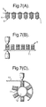
- FIG. 1 is a perspective view showing an embodiment of an armature of the present invention.
- FIG. 2 is a perspective view showing a structure of a pole piece of Figure 1.
- FIG. 3 is a section view showing a section of the wire piece of Figure 2.
- FIG. 4 is a magnetic characteristic chart of magnetic materials.
- FIG. 5 is a frequency characteristic chart of the magnetic materials.
- FIG. 6 is a frequency characteristic chart of permeability.
- FIG. 7 is a drawing showing steps of a first method for manufacturing of the armature in accordance with the invention.
- FIG. 8 is a drawing showing a method for creating the pole piece.
- FIG. 9 is a drawing showing another method for creating the pole piece.
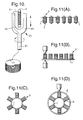
- FIG. 10 is a drawing diagrammatically showing a coil winding machine.
- FIG. 11 is a drawing showing steps of a second method for manufacturing of the armature in accordance with the invention.
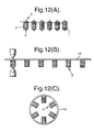
- FIG. 12 is a drawing showing steps of a third method for manufacturing of the armature in accordance with the invention.
- FIG. 13 is a drawing showing steps of a fourth method for manufacturing of the armature in accordance with the invention.
- FIG. 14 is a drawing showing steps of a fifth method for manufacturing of the armature in accordance with the invention.
- FIG. 15 is a section view showing a spindle motor having a motor armature as shown in FIG. 1.
- FIG. 1 is a perspective view of the preferred armature according to the invention, and, as shown in FIG. 1, the armature is constructed by disposing coaxially an inner cylinder 1 and an outer cylinder 2 and by providing a plurality of pole pieces 3 radially at equal intervals between the inner cylinder 1 and the outer cylinder 2.
- the inner cylinder 1 is formed into the cylinder shape by curling up or bending in the longitudinal direction a band or hoop member of steel which is made of a magnetic material and which has a predetermined thickness and length and by jointing the both ends thereof by welding or the like.
- the outer cylinder 2 is formed into the cylinder shape by bending in the longitudinal direction a band or hoop member of steel which is made of a magnetic material and which has a predetermined thickness and length and by jointing the both ends thereof by welding or the like.
- the pole piece 3 consists of a wire piece 3 obtained by cutting a wire (wire rod) which is made of a magnetic material and which has a predetermined thickness into a predetermined length and a coil 4 wound around the wire piece 5.
- a wire wire rod
- One end of the wire piece 5 is fixed to the outer peripheral face of the inner cylinder 1 by welding or the like and the other end of the wire piece 5 is fixed to the inner peripheral race or the outer cylinder 2.
- While the plurality of pole pieces 3 are provided between the inner cylinder 1 and the outer cylinder 2, the number thereof is determined depending on a design and specifications of a motor, like three, six, eight, nine or twelve.
- the wire piece 5 is obtained by cutting a wire and its shape of section is the same (circular) in the longitudinal direction, there is a merit that the coil 4 can be readily wound by a coil winding machine.
- the shape of the wire piece 5 is not limited only to such shape, and it is possible to provide fixing sections like convex sections at the both ends thereof so as to insert the convex sections to fixing holes provided on the inner cylinder 1 and the outer cylinder 2,
- sectional shape of the wire piece 5 in the longitudinal direction is not limited to be circular, and it may be triangular or square. Still more, the wire piece 5 may be formed by laminating thin plate-like members.
- the wire piece 5 is composed of a centre layer 5A whose section is circular and a skin layer 5B which is formed so as to have a constant thickness around the centre layer 5A.
- the centre layer 5A is made of low carbon steel or pure iron which are magnetic materials having high saturation magnetic flux density.
- the skin layer 5B is made of Fe-Co alloy, Fe-Ni alloy or amorphous alloy which are magnetic materials having high magnetic permeability and causing less iron loss. The reason why the wire piece 5 is composed of the two layers, using the magnetic materials having different natures, will be explained below.
- FIG. 4 is a magnetic characteristic chart of various magnetic materials.
- FIG. 5 is a frequency characteristic chart of iron loss the magnetic materials.
- FIG. 6 is a frequency characteristic chart of permeability of the magnetic materials. According to FIG. 4, when the strength of magnetic field is determined in order of a, b, c, d and e, the flux density corresponding to that is determined accordingly.
- the alternating frequency of the magnetic flux becomes high.
- the iron loss of the pure iron and the like increases remarkably in correspondence to the increase of the frequency
- the iron loss of the amorphous alloy and the like does not increase so much in correspondence to the increase of the frequency
- the Fe-Co alloy, Fe-Ni alloy or amorphous alloy is suited.
- the strength of the magnetic field is reduced because the current flowing through the coil decreases during the high speed rotation of the motor after the activation, the one having relatively high saturation magnetic flux density is suited, even though the strength of the magnetic field is small like the Fe-Co alloy, Fe-Ni alloy or amorphous alloy as shown in FIG. 4.
- the magnetic materials suited as the wire piece 5 are mutually contradictory in activating the motor and in rotating it at high speed after the activation and it is difficult to cover the whole range from the activation to the high speed rotation of the motor by either one of the magnetic materials. Therefore, it is conceivable to combine the two materials having the different natures.
- the alternating frequency of the magnetic flux is high so that it causes a skin effect of the magnetic flux.
- the magnetic flux density of the wire piece 5 on the skin side increases so that the wire piece 5 is caused less iron loss at the centre side thereof and caused large iron loss at the skin side thereof.
- the skin side of the wire piece 5 by the Fe-Co alloy, Fe-Ni alloy or amorphous alloy which causes less iron loss even when the frequency is high as shown in FIG. 5 in order to minimise the large iron loss at the skin side caused by the skin effect.
- the centre layer 5A of the wire piece 5 by the low carbon steel or pure iron which are the magnetic materials having high saturation magnetic flux density and to make the skin layer 5B by the Fe-Co alloy, Fe-Ni alloy or amorphous alloy which are the magnetic materials having high magnetic permeability and causing less iron loss.
- a loss caused by the iron loss may be reduced across the whole range from the activation to the high speed rotation of the motor. It also allows a magnetic flux necessary for driving to be obtained mainly by the centre layer 5A part in activating the motor and a magnetic flux necessary for rotation to be obtained mainly by the skin part 5B in rotating the motor at high speed.
- the iron loss caused by the skin effect of the magnetic flux may be reduced even if a number of rotation of the motor is increased from several thousands rpm to ten thousands rpm by composing the wire piece 5 as described above.
- the armature of the present embodiment constructed as described above may be used by combining either an inner rotor or an outer rotor made of permanent magnet for example.
- the armature may be modified in that the outer cylinder 2 is removed from the armature shown in FIG. 1 (armature which is composed of the pole pieces 3 and the inner cylinder 1).
- the armature of the present invention may also be modified in that the inner cylinder 1 is removed from the armature shown in FIG. 1 (armature which is composed of the pole pieces 3 and the outer cylinder 2).
- the armature is used by combining with an inner or outer rotor respectively.
- FIG. 7 is a process drawing for explaining a first method for manufacturing the armature.
- the coil 4 is wound as described later around the wire pieces 5 which are obtained by cutting a wire made of a magnetic material into a predetermined length to create the plurality of pole pieces 3 as shown in FIG. 7(A).
- six pole pieces 3 are created.
- one end of the wire piece 5 of the plurality of pole pieces 3 is fixed to a hoop member 11 which has been cut into a predetermined length beforehand at equal intervals by joint means such as spot welding or caulking as shown in FIG. 7 (B).
- each of the other end of the wire piece 5 of the pole pieces 3 is fixed to a hoop member 13 by means of spot welding or caulking to create the outer cylinder as shown in FIG. 7 (C). Then, the armature as showing FIG. 1 is completed.
- the inner cylinder may be created in advance by curling up the hoop member 11 on which the pole pieces 3 are fixed and the outer cylinder may be created thereafter by curling up the hoop member 13 as described above.
- pole piece 3 is created by winding the coil 4 around the wire piece 5 which has been cut in advance in FIG. 7(A), it is also possible, instead of that, to wind the coil 4 at the edge of the continuous wire in advance and to cut the wire into the length of the wire piece 5 after winding the coil 4.
- the one end of the pole piece 3 is fixed to the hoop member 11 which has been cut in advance in FIG. 7(B), it is also possible instead of that, to fix one end of the plurality of pole pieces 3 to the hoop member 11 and to cut the hoop member after finishing the fixation.
- FIG. 8 is a drawing diagrammatically showing a case of creating a three-phase coil by using three coil winding machines. In this case, the winding directions of the six pole pieces are all the same. Then, star connection or delta connection is made after that.
- FIG. 9 is a drawing diagrammatically showing a case of creating the three-phase coil by using one coil winding machine.
- the three poles of each phase of A, B and C are wound forward, backward and forward.
- a delta connection is made by hooking two spots to connect the beginning and the end of the winding as shown in FIG. 9.
- FIG. 10 is a drawing diagrammatically showing a coil winder 20 for winding the coil 4 around the wire piece 5.
- This coil winder 20 comprises a cylindrical base 21, a cylindrical winding section 22 which continues therefrom and bifurcates to the left side of the figure and a balance section 23 which bifurcates to the right side of the figure. It is constructed so that the whole of it moves forward and back while turning.
- the coil 4 In winding the coil 4 around the wire piece 5, the coil 4 is discharged from an opening at the edge of the winding section 22 via the base 21 and the winding section 22 and the whole coil winder 20 moves forward or back while turning. Thereby, the discharged coil 4 is wound around the wire piece 5. It is noted that the balance section 23 takes a balance when the winding section 22 turns.
- the rotation speed of the coil winding machine is around 3000 rpm at most in winding a coil around a prior art armature by means of the special coil winding machine because the structure of the armature is complicated.
- the wire piece 5 of the present mode is a rod whose section is circular in the longitudinal direction, there is a merit that the number of rotation of the coil winding machine may be increased up to 50,000 to 60,000 rpm in winding the coil 4 by the above-mentioned coil winding machine.
- the second manufacturing method is the same with the first manufacturing method up to the steps of creating the plurality of pole pieces 3 in which the coil 4 is wound around the wire piece 5 and of fixing one end of the wire piece 5 of the plurality of pole pieces 3 to the hoop member 11 at equal intervals (see Figs. 11(A) and 11(B)).
- the armature thus created by the second manufacturing method may be used in combination either with an inner rotor or an outer rotor.
- the armature in the state in FIG. 11(C) may be used in combination with the outer rotor.
- the third manufacturing method is the same with the first manufacturing method up to the steps of creating the plurality of pole pieces 3 in which the coil 4 is wound around the wire piece 5 and or fixing one end of the wire piece 5 of the plurality of pole pieces 3 at equal intervals to a hoop member 14 cut into a predetermined length in advance (see Figs. 12 (A) and 12(B)).
- the fourth manufacturing method is the same with the first manufacturing method up to the step of creating the plurality of pole pieces 3 in which the coil 4 is wound around the wire piece 5 (see FIG. 13(A)).
- One end of the wire piece 5 of the plurality of pole pieces 3 is fixed radially at equal intervals to the outer peripheral face of the inner cylinder 1 formed by curling up the hoop member as shown in FIG. 13(B) by means of spot welding or caulking.
- the plurality of pole pieces 3 in which the coil 4 is wound around the wire piece 5 are created and the wire piece 5 of the plurality of pole pieces 3 are fixed to the outer peripheral face of the inner cylinder 1 which has been formed by curling up the hoop member in the fourth method.
- the fifth manufacturing method is the same with the fourth manufacturing method up to the step of creating the plurality of pole pieces 3 in which the coil 4 is wound around the wire piece 5 (see FIG. 14(A)).
- each pole piece 3 One end of the wire piece 5 of each pole piece 3 is jointed to the inner peripheral face of the outer cylinder 2 created by curling up the hoop member so that each pole piece 3 heads the centre by means of spot welding or caulking as shown in FIG. 14(B).
- FIG. 15 is a sectional view of a high speed spindle motor using a motor armature shown in FIG. 1.
- a stator 31 which is formed by winding wirings around an iron core, namely, a motor armature is mounted at a position facing the magnet 32 mounted on the inner circumferential surface of the bottomed rotor 33 on the outer circumferential side of the stationary base 34.
- a central hole 35 is formed at the centre of the stationary base and a lower portion of cylindrical stationary shaft 36 is press-fitted into the central hole 35.
- a flange disc 37 for the bearing is provided coaxially with the stationary shaft 36 in the upper portion of the stationary shaft 36.
- this flange disc 15 is formed integrally with the stationary shaft 36, instead thereof, the flange disc 37 may be formed discretely from the stationary shaft 36 and may be coupled therewith by a suitable means.
- An oil feed hole 38 for feeding oil is provided in the axial direction of the inner central portion of the stationary shaft 36.
- An opening of the oil feed hole 38 may be covered by a sealing cover 39 after the replenishment of the oil.
- An outer circumferential surface of the flange disc 37 is formed as a radial dynamic pressure bearing portion 37f for supporting in the radial direction the rotary member composed of a bottomed rotor 33 and a thrust retaining portion 40.
- the top surface and the bottom surface of the flange disc 37 are formed into thrust dynamic pressure bearing portions 37a and 37c, respectively, for supporting in the axial direction the rotary member composed of the bottomed rotary 33 and the thrust retaining portion 40.
- the armature of the present invention is structured as described above, assembly is facilitated, the armature can be miniaturised and made more thin and its cost can be reduced. In addition, design changes in size and structure can be flexibly dealt with.
- the rod (wire piece) and the hoop members used in the manufacturing methods of the inventive armature facilitate automation and permit changes in design size and structure of the armature swiftly to be dealt with by changing the thickness of the wire piece or the thickness of the hoop member.
Landscapes
- Engineering & Computer Science (AREA)
- Power Engineering (AREA)
- Manufacturing & Machinery (AREA)
- Physics & Mathematics (AREA)
- Health & Medical Sciences (AREA)
- Life Sciences & Earth Sciences (AREA)
- Chemical & Material Sciences (AREA)
- Analytical Chemistry (AREA)
- Biochemistry (AREA)
- General Health & Medical Sciences (AREA)
- General Physics & Mathematics (AREA)
- Immunology (AREA)
- Pathology (AREA)
- Manufacture Of Motors, Generators (AREA)
- Iron Core Of Rotating Electric Machines (AREA)
- Windings For Motors And Generators (AREA)
Claims (10)
- Motoranker, umfassend:mehrere Polstücke (3), die jeweils eine Spule (4) umfassen, die um eine aus einem magnetischen Material gebildete Stange (5) gewickelt ist; und ferner gekennzeichnet durch:konzentrisch angeordnete erste (1) und zweite (2) Zylinder, die aus Bändern aus magnetischem Material gebildet sind, wobei die mehreren Polstücke sich zwischen diesen erstrecken und an beiden Zylindern befestigt sind.
- Motoranker nach Anspruch 1, bei dem die Polstücke radial in gleichmäßigen Intervallen angeordnet sind.
- Motoranker nach Anspruch 1 oder Anspruch 2, bei dem die Zylinder gebildet sind durch Biegen eines Bandelements aus magnetischem Material.
- Motoranker nach irgendeinem der vorangehenden Ansprüche, bei dem jede der Stangen gebildet wird durch Schneiden eines Drahtes.
- Motoranker nach irgendeinem der vorangehenden Ansprüche, bei dem jede der Stangen gebildet wird von einem magnetischen Kern aus einem Material mit hoher magnetischer Sättigungsflußdichte, wie z. B. kohlenstoffarmem Stahl oder Eisen, und einer äußeren Mantelschicht aus einem Material mit hoher magnetischer Permeabilität, wie z. B. Fe-Co-Legierung, Fe-Ni-Legierung oder einer amorphen Legierung.
- Verfahren zur Herstellung eines Motorankers, umfassend:einen Schritt des Erzeugens mehrerer Polstücke (3), in welchen jeweils eine Spule (4) um eine aus einem magnetischen Material gefertigte Stange (5) gewickelt ist; und ferner gekennzeichnet durch:einen Schritt des Befestigens jeweils eines Endes der mehreren Polstücke an der Innenumfangsfläche eines ersten Zylinders (2) und des jeweils anderen Endes der mehreren Polstücke an der Außenumfangsfläche eines zweiten konzentrischen Innenzylinders (1), wobei die Zylinder gebildet sind durch Biegen eines Bandelements aus einem magnetischen Material.
- Verfahren nach Anspruch 6, bei dem der Schritt des Befestigens umfaßt:einen ersten Schritt des Befestigens jeweils eines Endes der mehreren Polstücke an der gleichen Seite eines Bandelements (1, 2); undeinen zweiten Schritt des Erzeugens entweder des ersten Zylinders oder des zweiten Zylinders, an dem jeweils die Polstücke angebracht sind, durch Biegen des Bandelements, an dem die Polstücke angebracht sind, so daß die mehreren Polstücke innerhalb oder außerhalb des ersten Zylinders bzw. des zweiten Zylinders angeordnet sind.
- Verfahren nach Anspruch 6 oder Anspruch 7, bei dem die Polstücke zuerst außerhalb des zweiten Zylinders angeordnet werden und anschließend der erste Zylinder gebildet wird durch Biegen eines Bandes aus einem magnetischen Material und Befestigen des jeweils anderen Endes der mehreren Polstücke am ersten Zylinder.
- Verfahren nach Anspruch 6 oder Anspruch 7, bei dem die Polstücke zuerst innerhalb des ersten Zylinders angeordnet werden und anschließend der zweite Zylinder gebildet wird aus einem Band aus einem magnetischen Material und durch Befestigen des jeweils anderen Endes der mehreren Polstücke am zweiten Zylinder.
- Motor, der einen Motoranker nach irgendeinem der Ansprüche 1 bis 6 enthält.
Applications Claiming Priority (3)
| Application Number | Priority Date | Filing Date | Title |
|---|---|---|---|
| JP31020196 | 1996-11-06 | ||
| JP31020196A JP3405647B2 (ja) | 1996-11-06 | 1996-11-06 | モータの電機子およびその製造方法 |
| JP310201/96 | 1996-11-06 |
Publications (2)
| Publication Number | Publication Date |
|---|---|
| EP0841737A1 EP0841737A1 (de) | 1998-05-13 |
| EP0841737B1 true EP0841737B1 (de) | 2002-03-20 |
Family
ID=18002405
Family Applications (1)
| Application Number | Title | Priority Date | Filing Date |
|---|---|---|---|
| EP97308947A Expired - Lifetime EP0841737B1 (de) | 1996-11-06 | 1997-11-06 | Motoranker und Herstellungsverfahren |
Country Status (4)
| Country | Link |
|---|---|
| US (2) | US6163952A (de) |
| EP (1) | EP0841737B1 (de) |
| JP (1) | JP3405647B2 (de) |
| DE (1) | DE69711152T2 (de) |
Families Citing this family (22)
| Publication number | Priority date | Publication date | Assignee | Title |
|---|---|---|---|---|
| US6437464B1 (en) | 1999-07-29 | 2002-08-20 | Encap Motor Corporation | Motor and disc assembly for computer hard drive |
| US6753628B1 (en) | 1999-07-29 | 2004-06-22 | Encap Motor Corporation | High speed spindle motor for disc drive |
| US6617721B1 (en) | 1999-07-29 | 2003-09-09 | Encap Motor Corporation | High speed spindle motor |
| US6501616B1 (en) | 1999-07-29 | 2002-12-31 | Encap Motor Corporation | Hard disc drive with base incorporating a spindle motor stator |
| US6941644B2 (en) * | 1999-09-27 | 2005-09-13 | Reliance Electric Technologies, Llc | Method for winding segments of a segmented wound member of an electromechanical device |
| GB2355798B (en) | 1999-10-26 | 2004-05-19 | Oxford Magnet Tech | Improved magnetic coil former |
| US6844636B2 (en) | 1999-12-17 | 2005-01-18 | Encap Motor Corporation | Spindle motor with encapsulated stator and method of making same |
| JP2001224146A (ja) * | 2000-02-08 | 2001-08-17 | Sankyo Seiki Mfg Co Ltd | モータ |
| JP3520035B2 (ja) * | 2000-07-27 | 2004-04-19 | 三菱電機株式会社 | 始動用電動機の固定子 |
| US6892439B1 (en) | 2001-02-01 | 2005-05-17 | Encap Motor Corporation | Motor with stator made from linear core preform |
| US7036207B2 (en) | 2001-03-02 | 2006-05-02 | Encap Motor Corporation | Stator assembly made from a plurality of toroidal core segments and motor using same |
| US20030227230A1 (en) * | 2001-08-31 | 2003-12-11 | Daniel Gizaw | Exterior winding strategy for salient pole brushless motor for fuel pump application |
| JP2003244883A (ja) * | 2002-02-19 | 2003-08-29 | Hitachi Ltd | 外転型モータ及びそのモータ固定子の組立方法 |
| JP2006101673A (ja) * | 2004-09-30 | 2006-04-13 | Hitachi Industrial Equipment Systems Co Ltd | 永久磁石を備えた回転電機及びその固定子鉄心の歯部製造方法 |
| EP1715559A1 (de) * | 2005-04-22 | 2006-10-25 | Isa Innovations S.A. | Mit Nuten versehenes Teil eines elektrischen Motors |
| US7345398B2 (en) * | 2005-06-20 | 2008-03-18 | Kurz-Kasch, Inc. | Electric motor stator |
| JP5034376B2 (ja) * | 2006-08-29 | 2012-09-26 | ダイキン工業株式会社 | 磁心、電機子、回転電機及び圧縮機 |
| DE112008003234T5 (de) * | 2007-12-12 | 2010-10-14 | NTN Corporation, Osaka-shi | Drehungs-Übertragungsvorrichtung |
| WO2009100523A1 (en) * | 2008-02-11 | 2009-08-20 | Tm4 Inc. | Stator assembly for electric machines |
| DE102008041855A1 (de) * | 2008-09-08 | 2010-03-11 | Robert Bosch Gmbh | Verfahren zur Herstellung eines Stators in einem Innenläufer-Elektromotor |
| CN102832774A (zh) * | 2012-08-31 | 2012-12-19 | 南车株洲电机有限公司 | 一种凸极式同步电机的凸极磁极和一种电机 |
| EP3086441A1 (de) | 2015-04-24 | 2016-10-26 | Goodrich Actuation Systems SAS | Stator für einen wechselstrommotor für einen elektromechanischen aktuator |
Family Cites Families (19)
| Publication number | Priority date | Publication date | Assignee | Title |
|---|---|---|---|---|
| GB217597A (en) * | 1923-06-13 | 1925-05-07 | Quast & Co | Improvements in magneto-electric machines for velocipede lighting |
| US3914859A (en) * | 1974-01-17 | 1975-10-28 | Ray T Pierson | Method of fabricating closed slot stator construction particularly adapted for stepper motors |
| DE2644279C3 (de) * | 1976-09-30 | 1980-11-06 | Siemens Ag, 1000 Berlin Und 8000 Muenchen | Ständer für einen Mehrphasen-Elektromotor |
| US4182026A (en) * | 1977-08-17 | 1980-01-08 | Vibrac Corporation | Electric motor manufacture |
| US4350914A (en) * | 1977-08-17 | 1982-09-21 | Vibrac Corporation | Electric motor manufacture |
| US4193281A (en) * | 1978-04-24 | 1980-03-18 | Kulikov Valery A | Device for manufacturing coiled magnetic cores for electrical machines |
| US4438558A (en) * | 1979-04-16 | 1984-03-27 | Yoshiaki Mitsui | Laminated core manufacturing apparatus |
| US4296343A (en) * | 1979-10-05 | 1981-10-20 | Ambac Industries, Incorporated | Electric motor housing, or the like, with integral pole and methods for making same |
| JPS5895182U (ja) * | 1981-12-22 | 1983-06-28 | 三菱電機株式会社 | 直流電動機 |
| JPS60261341A (ja) * | 1984-06-05 | 1985-12-24 | Mitsubishi Electric Corp | 電動機用フレ−ムの製造方法 |
| CA1323650C (en) * | 1985-11-12 | 1993-10-26 | Franklin Lee Forbes | Electrically commutated motor having an edgewise wound yoke |
| US4712035A (en) * | 1985-11-12 | 1987-12-08 | General Electric Company | Salient pole core and salient pole electronically commutated motor |
| US5319844A (en) * | 1985-12-23 | 1994-06-14 | Unique Mobility, Inc. | Method of making an electromagnetic transducer |
| US5265323A (en) * | 1989-02-28 | 1993-11-30 | E. I. Du Pont De Nemours And Company | Method of fabricating a stator assembly for a non-static cogging brushless DC motor |
| US5005281A (en) * | 1990-08-20 | 1991-04-09 | Dynamics Systems International Inc. | Method of making rotor and stator pole assemblies by stamping magnetic plate |
| JPH04344137A (ja) * | 1991-05-20 | 1992-11-30 | Sanyo Electric Co Ltd | 電動機の固定子及び固定子の製造方法 |
| JPH06169556A (ja) * | 1992-11-30 | 1994-06-14 | Matsushita Electric Ind Co Ltd | 電動機の固定子製造方法およびその固定子鉄心 |
| US5481143A (en) * | 1993-11-15 | 1996-01-02 | Burdick; Brian K. | Self starting brushless d.c. motor |
| US5570503A (en) * | 1995-04-28 | 1996-11-05 | General Electric Company | Method for making an electric motor stator |
-
1996
- 1996-11-06 JP JP31020196A patent/JP3405647B2/ja not_active Expired - Fee Related
-
1997
- 1997-11-05 US US08/964,589 patent/US6163952A/en not_active Expired - Lifetime
- 1997-11-06 DE DE69711152T patent/DE69711152T2/de not_active Expired - Lifetime
- 1997-11-06 EP EP97308947A patent/EP0841737B1/de not_active Expired - Lifetime
-
2000
- 2000-10-31 US US09/703,145 patent/US6598288B1/en not_active Expired - Lifetime
Also Published As
| Publication number | Publication date |
|---|---|
| US6163952A (en) | 2000-12-26 |
| DE69711152T2 (de) | 2002-08-22 |
| JPH10145993A (ja) | 1998-05-29 |
| DE69711152D1 (de) | 2002-04-25 |
| EP0841737A1 (de) | 1998-05-13 |
| US6598288B1 (en) | 2003-07-29 |
| JP3405647B2 (ja) | 2003-05-12 |
Similar Documents
| Publication | Publication Date | Title |
|---|---|---|
| EP0841737B1 (de) | Motoranker und Herstellungsverfahren | |
| US6806615B2 (en) | Core, rotating machine using the core and production method thereof | |
| JP4234831B2 (ja) | アキシャルギャップモータ | |
| EP0862809B1 (de) | Von aussen bewickelter stator mit verbesserter magnetischer veränderbarkeit | |
| JPH06311675A (ja) | 分割形環状コア | |
| US5396138A (en) | Electric motor | |
| US20040016105A1 (en) | Method of making a stator for a motor | |
| JP5036442B2 (ja) | ステータおよびステータの製造方法 | |
| JP2005094927A (ja) | 回転電機および回転電機に用いられる電機子用駆動コイル | |
| US6008562A (en) | Rotor section containment with steel punched star | |
| JP2000175386A (ja) | トロイダルステータ | |
| JPH09163690A (ja) | 回転電機用ステータの製造方法及び回転電機用ステータ | |
| JP2583279Y2 (ja) | 回転電機の回転子 | |
| JP2945037B2 (ja) | 小型回転電機 | |
| JPS6259538B2 (de) | ||
| JPH10164805A (ja) | 電機子の製造方法 | |
| US7675214B2 (en) | Low profile motor | |
| JPH08149736A (ja) | 回転電機の回転子及びその分解組立て方法 | |
| JP2534164Y2 (ja) | 磁石発電機用固定子 | |
| JPH0746044Y2 (ja) | 回転電機の界磁構造 | |
| JP2020191749A (ja) | モータ | |
| JPH05292721A (ja) | シンクロ、レゾルバのステータ製造方法 | |
| JP2002291183A (ja) | 外転形回転電機の電機子製造方法及び該製造方法により製造された外転形回転電機の電機子 | |
| JPH09252572A (ja) | ステッピングモータのステータ及びステータコア部材 | |
| JPH069351U (ja) | 高速回転電機のスロットレス構造 |
Legal Events
| Date | Code | Title | Description |
|---|---|---|---|
| PUAI | Public reference made under article 153(3) epc to a published international application that has entered the european phase |
Free format text: ORIGINAL CODE: 0009012 |
|
| AK | Designated contracting states |
Kind code of ref document: A1 Designated state(s): DE GB |
|
| AX | Request for extension of the european patent |
Free format text: AL;LT;LV;MK;RO;SI |
|
| 17P | Request for examination filed |
Effective date: 19981106 |
|
| AKX | Designation fees paid |
Free format text: DE GB |
|
| RBV | Designated contracting states (corrected) |
Designated state(s): DE GB |
|
| 17Q | First examination report despatched |
Effective date: 20000124 |
|
| GRAG | Despatch of communication of intention to grant |
Free format text: ORIGINAL CODE: EPIDOS AGRA |
|
| GRAG | Despatch of communication of intention to grant |
Free format text: ORIGINAL CODE: EPIDOS AGRA |
|
| GRAH | Despatch of communication of intention to grant a patent |
Free format text: ORIGINAL CODE: EPIDOS IGRA |
|
| GRAH | Despatch of communication of intention to grant a patent |
Free format text: ORIGINAL CODE: EPIDOS IGRA |
|
| REG | Reference to a national code |
Ref country code: GB Ref legal event code: IF02 |
|
| GRAA | (expected) grant |
Free format text: ORIGINAL CODE: 0009210 |
|
| AK | Designated contracting states |
Kind code of ref document: B1 Designated state(s): DE GB |
|
| REF | Corresponds to: |
Ref document number: 69711152 Country of ref document: DE Date of ref document: 20020425 |
|
| PLBE | No opposition filed within time limit |
Free format text: ORIGINAL CODE: 0009261 |
|
| STAA | Information on the status of an ep patent application or granted ep patent |
Free format text: STATUS: NO OPPOSITION FILED WITHIN TIME LIMIT |
|
| 26N | No opposition filed |
Effective date: 20021223 |
|
| REG | Reference to a national code |
Ref country code: GB Ref legal event code: 732E |
|
| REG | Reference to a national code |
Ref country code: GB Ref legal event code: 732E Free format text: REGISTERED BETWEEN 20101104 AND 20101110 |
|
| REG | Reference to a national code |
Ref country code: DE Ref legal event code: R081 Ref document number: 69711152 Country of ref document: DE Owner name: SAMSUNG ELECTRO-MECHANICS CO., LTD., SUWON, KR Free format text: FORMER OWNER: SEIKO SEIKI K.K., NARASHINO, CHIBA, JP Effective date: 20110504 |
|
| PGFP | Annual fee paid to national office [announced via postgrant information from national office to epo] |
Ref country code: GB Payment date: 20140919 Year of fee payment: 18 |
|
| PGFP | Annual fee paid to national office [announced via postgrant information from national office to epo] |
Ref country code: DE Payment date: 20140919 Year of fee payment: 18 |
|
| REG | Reference to a national code |
Ref country code: DE Ref legal event code: R119 Ref document number: 69711152 Country of ref document: DE |
|
| GBPC | Gb: european patent ceased through non-payment of renewal fee |
Effective date: 20151106 |
|
| PG25 | Lapsed in a contracting state [announced via postgrant information from national office to epo] |
Ref country code: GB Free format text: LAPSE BECAUSE OF NON-PAYMENT OF DUE FEES Effective date: 20151106 Ref country code: DE Free format text: LAPSE BECAUSE OF NON-PAYMENT OF DUE FEES Effective date: 20160601 |