EP0840536B1 - Schalteinrichtung für eine Treppenhausbeleuchtung - Google Patents
Schalteinrichtung für eine Treppenhausbeleuchtung Download PDFInfo
- Publication number
- EP0840536B1 EP0840536B1 EP19970118600 EP97118600A EP0840536B1 EP 0840536 B1 EP0840536 B1 EP 0840536B1 EP 19970118600 EP19970118600 EP 19970118600 EP 97118600 A EP97118600 A EP 97118600A EP 0840536 B1 EP0840536 B1 EP 0840536B1
- Authority
- EP
- European Patent Office
- Prior art keywords
- stairs
- detection area
- motion detector
- lighting
- flight
- Prior art date
- Legal status (The legal status is an assumption and is not a legal conclusion. Google has not performed a legal analysis and makes no representation as to the accuracy of the status listed.)
- Expired - Lifetime
Links
Images

Classifications
-
- H—ELECTRICITY
- H05—ELECTRIC TECHNIQUES NOT OTHERWISE PROVIDED FOR
- H05B—ELECTRIC HEATING; ELECTRIC LIGHT SOURCES NOT OTHERWISE PROVIDED FOR; CIRCUIT ARRANGEMENTS FOR ELECTRIC LIGHT SOURCES, IN GENERAL
- H05B47/00—Circuit arrangements for operating light sources in general, i.e. where the type of light source is not relevant
- H05B47/10—Controlling the light source
- H05B47/105—Controlling the light source in response to determined parameters
- H05B47/115—Controlling the light source in response to determined parameters by determining the presence or movement of objects or living beings
-
- E—FIXED CONSTRUCTIONS
- E04—BUILDING
- E04F—FINISHING WORK ON BUILDINGS, e.g. STAIRS, FLOORS
- E04F11/00—Stairways, ramps, or like structures; Balustrades; Handrails
- E04F11/02—Stairways; Layouts thereof
- E04F11/104—Treads
- E04F2011/1046—Miscellaneous features of treads not otherwise provided for
- E04F2011/1048—Miscellaneous features of treads not otherwise provided for with lighting means
-
- Y—GENERAL TAGGING OF NEW TECHNOLOGICAL DEVELOPMENTS; GENERAL TAGGING OF CROSS-SECTIONAL TECHNOLOGIES SPANNING OVER SEVERAL SECTIONS OF THE IPC; TECHNICAL SUBJECTS COVERED BY FORMER USPC CROSS-REFERENCE ART COLLECTIONS [XRACs] AND DIGESTS
- Y02—TECHNOLOGIES OR APPLICATIONS FOR MITIGATION OR ADAPTATION AGAINST CLIMATE CHANGE
- Y02B—CLIMATE CHANGE MITIGATION TECHNOLOGIES RELATED TO BUILDINGS, e.g. HOUSING, HOUSE APPLIANCES OR RELATED END-USER APPLICATIONS
- Y02B20/00—Energy efficient lighting technologies, e.g. halogen lamps or gas discharge lamps
- Y02B20/40—Control techniques providing energy savings, e.g. smart controller or presence detection
Definitions
- the invention relates to a lighting arrangement in a staircase according to the preamble of claim 1.
- Stairwell lighting has long been known per se. Among them are usually Understand circuit arrangements that allow multi-storey Build the paths designed in the form of stairs with enough light to illuminate. A distinction must be made here between different stairwell lighting.
- staircase lighting has switches and lamps on which are interconnected and create the possibility of any Place the stairwell by manually operating the one located there Switch the light on, so that the path in question over the stairs is illuminated, and turn off the light after reaching the destination.
- An improved form of staircase lighting is with a Combined timer, which automatically ensures that this is done by manual switch operation switched on light in the staircase after a previously set Period is switched off again.
- the actuation leads to one of them Circuit of the staircase circuit integrated switching device that all lamps are switched on and only after renewed manual or from Timing operation of a switching device is turned off again. Especially for large stairwells with many lamps, for example in High-rise buildings, this leads to unnecessary power consumption, since the respective person, which has switched on the light, only the lighting of the one in question Stair section needed.
- US-A-4 843 283 is a lighting control system with a plurality known from infrared detection systems, which a plurality of each adjacent Monitor scan areas.
- an infrared motion detector is known, the rear wall of the housing carries two infrared sensors, which means the light field on the local conditions can be adjusted.
- EP-A-652 422 is an infrared motion detector with two light sensors and Lens segments known, the processing of the electrical output signals the light sensors are carried out separately.
- the switching devices work together with motion detectors, which each monitor at least a single section of stairs and the operating current for supplying the lamps assigned to this section switch. This ensures that only the so-called active area, that is, the section of stairs currently to be illuminated is illuminated. This is because the detection range of the sensors used in the motion detectors and their short response time between the person's entry into the relevant area on the one hand and detection and switching on the other as unproblematic.
- each motion detector has a performing and a laxative section of stairs and monitors the operating current for everyone Lights that are assigned to these stair sections.
- a motion detector suitable for a device of the type described above, usually with optics, with at least one sensor and one this sensor associated switch module for connecting conductors is according to the invention characterized in that the optics in two separate detection areas is divided, each of which has a sensor with an associated one Switch module is assigned.
- a first detection area is used the optics for monitoring the performing section of the staircase and the second detection area of the optics for monitoring the draining section of stairs.
- the optics for such motion detectors are advantageously for each detection area each with all the lenses that are available in the large number of structural Design might be needed. By shielding or masking The optics can then use lenses with a view to the special local requirements to the stairway sections to be monitored and their geometric Conditions are adjusted.
- An alternative design can be that the lenses of the optics of the motion detector can be replaced individually for each detection area and so for each staircase section to be monitored in accordance with its construction Conditions are adaptable, that is, depending on the local conditions special lens arrangements put together and on the motion detector appropriate.
- the motion detector is designed for installation in a mounting surface as a flush-mounted device at which only the optics protrude from the mounting surface. This can the motion detector can be integrated into the existing architecture without being distracting to attract attention.
- a timer is preferably integrated in the switching module. This timer switches the operating current again only after a preset period of time from.
- Fig. 1 is a schematic plan view of the floor plan of a Motion detector 10, as used in the device according to the invention is coming. Based on this representation, the specialty clearly that the motion detector 10 two separate systems I and II has, which in a common housing 12 consisting of an installation part 14 and a surface-mounted part 16 with a two-part optics 18 arranged thereon are accommodated.
- Each of the systems I and II has a specially assigned lens arrangement 20, 21, which is part of the optics 18 and through which to be detected Beam signals are directed to a respectively assigned sensor 22, 23.
- the Sensors 22, 23 are in turn each with an associated switching module 24, 25 connected, which is the required switching operation for switching the current makes the each in the stair section 30, 31 as he shown in Fig. 3, provided lamps.
- the two systems I and II are dashed along one in FIG. 1 and also in FIG. 2 drawn line "S" separated. Accordingly, the sensors 22, 23, which record the signals to be recorded, correspondingly at an angle to this System boundary set.
- signal-enhancing or focusing lens elements 26, 27 are placed facing the area to be detected, i.e. in the example shown there are such lens elements 26, 27 on the upper edge of the optics 18 when the area 30 to be detected is directed upstairs and on the lower edge of the optics 18 when the area 31 to be detected is directed downstairs. This is illustrated by dashed lines B I and B II assigned to the two systems
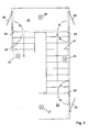
- Fig. 3 is a part of a staircase with access doors 28 and one first stair section 30 and with a second stair section 31 in plan view shown, each of which is assigned a landing 32, 33.
- Each of these stair sections 30, 31 to be illuminated with the landing 32, 33 lamps 34, 33, 35, 36, 37 are assigned, which with motion detectors 38, 39, 40 work together.
- the motion detectors 38, 39, 40 arranged on the longitudinal side walls of the staircase each detect two areas delimited by dashed lines B I and B II .
- the respective neighboring systems of mutually adjacent motion detectors 38, 39, 40 work together to the extent that they supply the same lamps with electricity as soon as a person is in their detection range.
- the function of the switching device according to the invention as staircase lighting is to be explained on the basis of the arrangement shown in FIG. 3.
- a person, not shown, is on the landing 32 where, depending on the location, it is detected by the detection area B I of the motion detector 39 or by the detection area B II of the motion detector 38, which then switches on the lamp 36.
Landscapes
- Circuit Arrangement For Electric Light Sources In General (AREA)
- Steps, Ramps, And Handrails (AREA)
- Vending Machines For Individual Products (AREA)
Description
- Fig. 1
- eine schematische Draufsicht auf einen Bewegungsmelder, wie er bei der erfindungsgemäßen Beleuchtungseinrichtung zur Anwendung kommt
- Fig. 2
- Frontansicht des Bewegungsmelders gemäß Fig. 1 und
- Fig. 3
- eine auszugsweise Draufsicht auf den Grundriß eines Treppenhauses in dem die erfindungsgemäße Beleuchtungseinrichtung zur Anwendung kommt.
Claims (6)
- Beleuchtungsanordnung in einem Treppenhaus mit Treppenabsätzen (32, 33), welche über aufführende und abführende Treppenabschnitte (30, 31) miteinander verbunden sind, wobei jeder Treppenabsatz und jeder Treppenabschnitt mit mindestens einer Lampe (34, 35, 36, 37) zur bedarfsgerechten Beleuchtung versehen ist, dadurch gekennzeichnet, daß bei mindestens einem Treppenabsatz (32) zwei Bewegungsmelder (38, 39) angeordnet sind, jeweils einer an jeder Längsseitenwand des Treppenhauses, und welche jeweils zwei getrennte Erfassungsbereiche überwachen, wobeider erste Erfassungsbereich (BI) des ersten Bewegungsmelders (38) zur Überwachung des abführenden Treppenabschnittes (3),der zweite Erfassungsbereich (BII) des ersten Bewegungsmelders (38) zur Überwachung des vor dem abführenden Treppenabschnitt befindlichen Teilbereichs des Treppenabsatzes (32),der zweite Erfassungsbereich (BII) des zweiten Bewegungsmelders (39) zur Überwachung des aufführenden Treppenabschnitts (31),der erste Erfassungsbereich (BI) des zweiten Bewegungsmelders (39) zur Überwachung des vor dem aufführenden Treppenabschnitt befindlichen Teilbereichs des Treppenabsatzes (32) dient und wobeiüber den ersten Erfassungsbereich des ersten Bewegungsmelders (38) der Betriebsstrom zur Versorgung der den abführenden Treppenabschnitt (30) beleuchtenden Lampe (34),über den zweiten Erfassungsbereich des zweiten Bewegungsmelders (39) der Betriebsstrom zur Versorgung der den aufführenden Treppenabschnitt (31) beleuchtenden Lampe (35) undsowohl über den ersten Erfassungsbereich des ersten (38) als auch über den zweiten Erfassungsbereich des zweiten Bewegungsmelders (39) der Betriebsstrom zur Versorgung der den Treppenabsatz (32) beleuchtenden Lampe (36) geschaltet wird.
- Beleuchtungsanordnung nach Anspruch 1, dadurch gekennzeichnet, daß die Optiken der Bewegungsmelder für jeden Erfassungsbereich jeweils mit sämtlichen Linsen versehen sind und mittels Abschirmen oder Abkleben von Linsen an die zu überwachenden Treppenabschnitte und deren geometrische Verhältnisse anpaßbar ist.
- Beleuchtungsanordnung nach Anspruch 1, dadurch gekennzeichnet, daß die Linsen der Optiken der Bewegungsmelder für jeden Erfassungsbereich einzeln auswechselbar und so für jeden zu überwachenden Treppenabschnitt entsprechend dessen baulicher Verhältnisse anpaßbar sind.
- Beleuchtungsanordnung nach einem der vorstehenden Ansprüche, dadurch gekennzeichnet, daß die Bewegungsmelder zum Einbau in eine Montagefläche als UP-Geräte ausgebildet sind, bei welchen lediglich die Optiken aus der Montagefläche hervorragen.
- Beleuchtungsanordnung nach einem der vorstehenden Ansprüche, dadurch gekennzeichnet, daß die Bewegungsmelder ein Zeitglied aufweisen, welches mit dem Schaltbaustein zusammenarbeitet und den angeforderten Betriebsstrom nach Ablauf einer voreingestellten Zeitspanne wieder abschaltet.
- Beleuchtungsanordnung nach Anspruch 5, dadurch gekennzeichnet, daß das Zeitglied in den Schaltbaustein integriert ist.
Applications Claiming Priority (2)
| Application Number | Priority Date | Filing Date | Title |
|---|---|---|---|
| DE1996145184 DE19645184A1 (de) | 1996-11-02 | 1996-11-02 | Schalteinrichtung für eine Treppenhausbeleuchtung |
| DE19645184 | 1996-11-02 |
Publications (3)
| Publication Number | Publication Date |
|---|---|
| EP0840536A2 EP0840536A2 (de) | 1998-05-06 |
| EP0840536A3 EP0840536A3 (de) | 1999-03-03 |
| EP0840536B1 true EP0840536B1 (de) | 2000-08-09 |
Family
ID=7810462
Family Applications (1)
| Application Number | Title | Priority Date | Filing Date |
|---|---|---|---|
| EP19970118600 Expired - Lifetime EP0840536B1 (de) | 1996-11-02 | 1997-10-25 | Schalteinrichtung für eine Treppenhausbeleuchtung |
Country Status (7)
| Country | Link |
|---|---|
| EP (1) | EP0840536B1 (de) |
| AT (1) | ATE195397T1 (de) |
| CZ (1) | CZ347197A3 (de) |
| DE (2) | DE19645184A1 (de) |
| ES (1) | ES2150729T3 (de) |
| NO (1) | NO975014L (de) |
| PL (1) | PL322939A1 (de) |
Families Citing this family (5)
| Publication number | Priority date | Publication date | Assignee | Title |
|---|---|---|---|---|
| ES2162760B1 (es) * | 2000-03-29 | 2003-04-01 | Bezanilla Enrique Fr Gasso | Sistema de encendido selectivo para alumbrado de zonas comunes de edificaciones. |
| DE10242483A1 (de) * | 2002-09-13 | 2004-03-25 | Abb Patent Gmbh | Passiv-Infrarot-Bewegungsmelder mit wenigstens zwei optischen Systemen |
| DE50311772D1 (de) * | 2002-10-09 | 2009-09-17 | Manfred Kluth | Beleuchtungseinrichtung mit Sensoren |
| US20110024631A1 (en) * | 2009-07-29 | 2011-02-03 | Jian Xu | Motion sensor mounting configuration |
| DE102019103889A1 (de) * | 2018-12-06 | 2020-06-10 | Siteco Gmbh | Ein- und Auskoppelung von Daten und Datentransport über elektrische Versorgungsleitung von Beleuchtungssystemen |
Family Cites Families (7)
| Publication number | Priority date | Publication date | Assignee | Title |
|---|---|---|---|---|
| US4843283A (en) * | 1987-08-24 | 1989-06-27 | Chen Jack Y C | Infrared ray detector control illumination system |
| DE3744399C2 (de) * | 1987-12-29 | 1997-03-13 | Asea Brown Boveri | Strahlungsempfindlicher Schalter |
| DE8816609U1 (de) * | 1988-02-04 | 1990-01-11 | B.E.G. Brueck Electronic Gmbh, 5253 Lindlar, De | |
| JPH03261094A (ja) * | 1990-03-09 | 1991-11-20 | Sekisui Chem Co Ltd | 自動点消灯制御装置 |
| DE4100536A1 (de) * | 1991-01-10 | 1992-07-16 | Hochkoepper Paul Gmbh | Infrarotbewegungsmelder |
| DE4337953A1 (de) * | 1993-11-06 | 1995-05-11 | Abb Patent Gmbh | Vorrichtung zur Erfassung von Lichtstrahlen |
| DE4411357A1 (de) * | 1994-03-31 | 1995-10-05 | Prompt Kommunikationstechnik G | Verfahren und Schaltungsanordnung zur Steuerung elektrischer Verbraucher |
-
1996
- 1996-11-02 DE DE1996145184 patent/DE19645184A1/de not_active Withdrawn
-
1997
- 1997-10-25 DE DE59702136T patent/DE59702136D1/de not_active Expired - Fee Related
- 1997-10-25 ES ES97118600T patent/ES2150729T3/es not_active Expired - Lifetime
- 1997-10-25 EP EP19970118600 patent/EP0840536B1/de not_active Expired - Lifetime
- 1997-10-25 AT AT97118600T patent/ATE195397T1/de not_active IP Right Cessation
- 1997-10-31 CZ CZ973471A patent/CZ347197A3/cs unknown
- 1997-10-31 PL PL32293997A patent/PL322939A1/xx unknown
- 1997-10-31 NO NO975014A patent/NO975014L/no unknown
Also Published As
| Publication number | Publication date |
|---|---|
| CZ347197A3 (cs) | 1998-05-13 |
| PL322939A1 (en) | 1998-05-11 |
| DE19645184A1 (de) | 1998-05-07 |
| ES2150729T3 (es) | 2000-12-01 |
| EP0840536A3 (de) | 1999-03-03 |
| DE59702136D1 (de) | 2000-09-14 |
| NO975014D0 (no) | 1997-10-31 |
| ATE195397T1 (de) | 2000-08-15 |
| NO975014L (no) | 1998-05-04 |
| EP0840536A2 (de) | 1998-05-06 |
Similar Documents
| Publication | Publication Date | Title |
|---|---|---|
| DE2922471A1 (de) | Passanten-zaehlvorrichtung | |
| EP1541519A1 (de) | Einrichtung zur Vorraumüberwachung für Fahrtreppen und Fahrsteige mit Hochfrequenz-Sensoren | |
| EP3083480A1 (de) | Anordnung eines überwachungssensors in einer fahrtreppe oder in einem fahrsteig | |
| DE3540680C2 (de) | Passiver Infrarot-Bewegungsempfänger mit Sensor für die Umgebungshelligkeit | |
| EP1013599A1 (de) | Sicherheitseinrichtung für eine Fahrtreppe oder einen Fahrsteig | |
| EP0840536B1 (de) | Schalteinrichtung für eine Treppenhausbeleuchtung | |
| DE102009042257A1 (de) | Handlauf mit integrierten Leuchtmitteln | |
| EP1398742B1 (de) | Passiv-Infrarot-Bewegungsmelder mit wenigstens zwei optischen Systemen | |
| DE112013001922T5 (de) | Beleuchtungssystem und Unterstützungsvorrichtung | |
| DE4241862C2 (de) | Sicherheitssystem sowie Verfahren, mit dem das Sicherheitssystem betrieben wird | |
| DE19722406B4 (de) | Rettungszeichenleuchte und Sicherheitssystem | |
| WO2006042694A1 (de) | Entwässerungsrinne | |
| EP0669786B1 (de) | Sicherheitsbeleuchtung | |
| EP0201920A1 (de) | Mehrscheiben-Isolierglaseinheit mit integriertem lichtlenkenden System | |
| WO2001071389A2 (de) | Einrichtung zur automatischen schaltung von beleuchtungseinrichtungen bei fahrzeugen | |
| DE10353523A1 (de) | Geländerelement mit Beleuchtung | |
| EP2923989A1 (de) | Zutrittsbereich einer Fahrtreppe oder eines Fahrsteiges mit einer Anzeigeeinrichtung | |
| EP1387330B1 (de) | Passiv-Infrarot-Bewegungsmelder | |
| DE10123006B4 (de) | Leuchtvorrichtung zur Erzeugung einer aktiv nachleuchtenden Signalfläche | |
| DE19624569C2 (de) | Bewegungsmelder mit optimaler Ausleuchtung der Umgebung bei einem einzigen Bewegungssensor und zwei Schaltmitteln | |
| EP0459090A1 (de) | Vorrichtung zur selbsttätigen Erhaltung der Kontinuität von Lichtsignal- o. ä. Beleuchtungsanlagen | |
| DE19830271A1 (de) | Beleuchtungseinrichtung in Modulbauweise | |
| DE3927636C1 (de) | ||
| EP0847956B1 (de) | Einrichtung zur Vorraumüberwachung für Fahrtreppen und Fahrsteige | |
| DE2437340C3 (de) | Alarmanlage |
Legal Events
| Date | Code | Title | Description |
|---|---|---|---|
| PUAI | Public reference made under article 153(3) epc to a published international application that has entered the european phase |
Free format text: ORIGINAL CODE: 0009012 |
|
| AK | Designated contracting states |
Kind code of ref document: A2 Designated state(s): AT BE CH DE ES FI FR LI NL SE |
|
| PUAL | Search report despatched |
Free format text: ORIGINAL CODE: 0009013 |
|
| AK | Designated contracting states |
Kind code of ref document: A3 Designated state(s): AT BE CH DE DK ES FI FR GB GR IE IT LI LU MC NL PT SE |
|
| 17P | Request for examination filed |
Effective date: 19990409 |
|
| 17Q | First examination report despatched |
Effective date: 19990607 |
|
| AKX | Designation fees paid |
Free format text: AT BE CH DE ES FI FR LI NL SE |
|
| GRAG | Despatch of communication of intention to grant |
Free format text: ORIGINAL CODE: EPIDOS AGRA |
|
| GRAG | Despatch of communication of intention to grant |
Free format text: ORIGINAL CODE: EPIDOS AGRA |
|
| GRAH | Despatch of communication of intention to grant a patent |
Free format text: ORIGINAL CODE: EPIDOS IGRA |
|
| 17Q | First examination report despatched |
Effective date: 19990607 |
|
| GRAH | Despatch of communication of intention to grant a patent |
Free format text: ORIGINAL CODE: EPIDOS IGRA |
|
| GRAA | (expected) grant |
Free format text: ORIGINAL CODE: 0009210 |
|
| AK | Designated contracting states |
Kind code of ref document: B1 Designated state(s): AT BE CH DE ES FI FR LI NL SE |
|
| REF | Corresponds to: |
Ref document number: 195397 Country of ref document: AT Date of ref document: 20000815 Kind code of ref document: T |
|
| REG | Reference to a national code |
Ref country code: CH Ref legal event code: EP |
|
| ET | Fr: translation filed | ||
| REF | Corresponds to: |
Ref document number: 59702136 Country of ref document: DE Date of ref document: 20000914 |
|
| PGFP | Annual fee paid to national office [announced via postgrant information from national office to epo] |
Ref country code: FI Payment date: 20001011 Year of fee payment: 4 |
|
| REG | Reference to a national code |
Ref country code: ES Ref legal event code: FG2A Ref document number: 2150729 Country of ref document: ES Kind code of ref document: T3 |
|
| PLBE | No opposition filed within time limit |
Free format text: ORIGINAL CODE: 0009261 |
|
| STAA | Information on the status of an ep patent application or granted ep patent |
Free format text: STATUS: NO OPPOSITION FILED WITHIN TIME LIMIT |
|
| 26N | No opposition filed | ||
| PGFP | Annual fee paid to national office [announced via postgrant information from national office to epo] |
Ref country code: NL Payment date: 20010824 Year of fee payment: 5 Ref country code: AT Payment date: 20010824 Year of fee payment: 5 |
|
| PGFP | Annual fee paid to national office [announced via postgrant information from national office to epo] |
Ref country code: CH Payment date: 20010827 Year of fee payment: 5 |
|
| PGFP | Annual fee paid to national office [announced via postgrant information from national office to epo] |
Ref country code: SE Payment date: 20010828 Year of fee payment: 5 Ref country code: FR Payment date: 20010828 Year of fee payment: 5 |
|
| PGFP | Annual fee paid to national office [announced via postgrant information from national office to epo] |
Ref country code: ES Payment date: 20010920 Year of fee payment: 5 |
|
| PGFP | Annual fee paid to national office [announced via postgrant information from national office to epo] |
Ref country code: BE Payment date: 20011011 Year of fee payment: 5 |
|
| PG25 | Lapsed in a contracting state [announced via postgrant information from national office to epo] |
Ref country code: FI Free format text: LAPSE BECAUSE OF NON-PAYMENT OF DUE FEES Effective date: 20011025 |
|
| PG25 | Lapsed in a contracting state [announced via postgrant information from national office to epo] |
Ref country code: AT Free format text: LAPSE BECAUSE OF NON-PAYMENT OF DUE FEES Effective date: 20021025 |
|
| PG25 | Lapsed in a contracting state [announced via postgrant information from national office to epo] |
Ref country code: SE Free format text: LAPSE BECAUSE OF NON-PAYMENT OF DUE FEES Effective date: 20021026 Ref country code: ES Free format text: LAPSE BECAUSE OF NON-PAYMENT OF DUE FEES Effective date: 20021026 |
|
| PG25 | Lapsed in a contracting state [announced via postgrant information from national office to epo] |
Ref country code: LI Free format text: LAPSE BECAUSE OF NON-PAYMENT OF DUE FEES Effective date: 20021031 Ref country code: CH Free format text: LAPSE BECAUSE OF NON-PAYMENT OF DUE FEES Effective date: 20021031 Ref country code: BE Free format text: LAPSE BECAUSE OF NON-PAYMENT OF DUE FEES Effective date: 20021031 |
|
| BERE | Be: lapsed |
Owner name: *ABB PATENT G.M.B.H. Effective date: 20021031 |
|
| PG25 | Lapsed in a contracting state [announced via postgrant information from national office to epo] |
Ref country code: NL Free format text: LAPSE BECAUSE OF NON-PAYMENT OF DUE FEES Effective date: 20030501 |
|
| EUG | Se: european patent has lapsed | ||
| REG | Reference to a national code |
Ref country code: CH Ref legal event code: PL |
|
| PG25 | Lapsed in a contracting state [announced via postgrant information from national office to epo] |
Ref country code: FR Free format text: LAPSE BECAUSE OF NON-PAYMENT OF DUE FEES Effective date: 20030630 |
|
| NLV4 | Nl: lapsed or anulled due to non-payment of the annual fee |
Effective date: 20030501 |
|
| REG | Reference to a national code |
Ref country code: FR Ref legal event code: ST |
|
| PGFP | Annual fee paid to national office [announced via postgrant information from national office to epo] |
Ref country code: DE Payment date: 20030908 Year of fee payment: 7 |
|
| REG | Reference to a national code |
Ref country code: ES Ref legal event code: FD2A Effective date: 20031112 |
|
| PG25 | Lapsed in a contracting state [announced via postgrant information from national office to epo] |
Ref country code: DE Free format text: LAPSE BECAUSE OF NON-PAYMENT OF DUE FEES Effective date: 20050503 |