EP0835707A2 - Table de perçage - Google Patents
Table de perçage Download PDFInfo
- Publication number
- EP0835707A2 EP0835707A2 EP97116422A EP97116422A EP0835707A2 EP 0835707 A2 EP0835707 A2 EP 0835707A2 EP 97116422 A EP97116422 A EP 97116422A EP 97116422 A EP97116422 A EP 97116422A EP 0835707 A2 EP0835707 A2 EP 0835707A2
- Authority
- EP
- European Patent Office
- Prior art keywords
- workpiece plate
- drilling
- rollers
- drilling table
- lifting device
- Prior art date
- Legal status (The legal status is an assumption and is not a legal conclusion. Google has not performed a legal analysis and makes no representation as to the accuracy of the status listed.)
- Withdrawn
Links
Images


Classifications
-
- B—PERFORMING OPERATIONS; TRANSPORTING
- B23—MACHINE TOOLS; METAL-WORKING NOT OTHERWISE PROVIDED FOR
- B23Q—DETAILS, COMPONENTS, OR ACCESSORIES FOR MACHINE TOOLS, e.g. ARRANGEMENTS FOR COPYING OR CONTROLLING; MACHINE TOOLS IN GENERAL CHARACTERISED BY THE CONSTRUCTION OF PARTICULAR DETAILS OR COMPONENTS; COMBINATIONS OR ASSOCIATIONS OF METAL-WORKING MACHINES, NOT DIRECTED TO A PARTICULAR RESULT
- B23Q7/00—Arrangements for handling work specially combined with or arranged in, or specially adapted for use in connection with, machine tools, e.g. for conveying, loading, positioning, discharging, sorting
- B23Q7/05—Arrangements for handling work specially combined with or arranged in, or specially adapted for use in connection with, machine tools, e.g. for conveying, loading, positioning, discharging, sorting by means of roller-ways
-
- B—PERFORMING OPERATIONS; TRANSPORTING
- B23—MACHINE TOOLS; METAL-WORKING NOT OTHERWISE PROVIDED FOR
- B23Q—DETAILS, COMPONENTS, OR ACCESSORIES FOR MACHINE TOOLS, e.g. ARRANGEMENTS FOR COPYING OR CONTROLLING; MACHINE TOOLS IN GENERAL CHARACTERISED BY THE CONSTRUCTION OF PARTICULAR DETAILS OR COMPONENTS; COMBINATIONS OR ASSOCIATIONS OF METAL-WORKING MACHINES, NOT DIRECTED TO A PARTICULAR RESULT
- B23Q1/00—Members which are comprised in the general build-up of a form of machine, particularly relatively large fixed members
- B23Q1/03—Stationary work or tool supports
-
- B—PERFORMING OPERATIONS; TRANSPORTING
- B23—MACHINE TOOLS; METAL-WORKING NOT OTHERWISE PROVIDED FOR
- B23Q—DETAILS, COMPONENTS, OR ACCESSORIES FOR MACHINE TOOLS, e.g. ARRANGEMENTS FOR COPYING OR CONTROLLING; MACHINE TOOLS IN GENERAL CHARACTERISED BY THE CONSTRUCTION OF PARTICULAR DETAILS OR COMPONENTS; COMBINATIONS OR ASSOCIATIONS OF METAL-WORKING MACHINES, NOT DIRECTED TO A PARTICULAR RESULT
- B23Q1/00—Members which are comprised in the general build-up of a form of machine, particularly relatively large fixed members
- B23Q1/25—Movable or adjustable work or tool supports
- B23Q1/44—Movable or adjustable work or tool supports using particular mechanisms
- B23Q1/50—Movable or adjustable work or tool supports using particular mechanisms with rotating pairs only, the rotating pairs being the first two elements of the mechanism
- B23Q1/54—Movable or adjustable work or tool supports using particular mechanisms with rotating pairs only, the rotating pairs being the first two elements of the mechanism two rotating pairs only
- B23Q1/5468—Movable or adjustable work or tool supports using particular mechanisms with rotating pairs only, the rotating pairs being the first two elements of the mechanism two rotating pairs only a single rotating pair followed parallelly by a single rotating pair
- B23Q1/5481—Movable or adjustable work or tool supports using particular mechanisms with rotating pairs only, the rotating pairs being the first two elements of the mechanism two rotating pairs only a single rotating pair followed parallelly by a single rotating pair followed parallelly by a single rotating pair
-
- B—PERFORMING OPERATIONS; TRANSPORTING
- B23—MACHINE TOOLS; METAL-WORKING NOT OTHERWISE PROVIDED FOR
- B23Q—DETAILS, COMPONENTS, OR ACCESSORIES FOR MACHINE TOOLS, e.g. ARRANGEMENTS FOR COPYING OR CONTROLLING; MACHINE TOOLS IN GENERAL CHARACTERISED BY THE CONSTRUCTION OF PARTICULAR DETAILS OR COMPONENTS; COMBINATIONS OR ASSOCIATIONS OF METAL-WORKING MACHINES, NOT DIRECTED TO A PARTICULAR RESULT
- B23Q1/00—Members which are comprised in the general build-up of a form of machine, particularly relatively large fixed members
- B23Q1/25—Movable or adjustable work or tool supports
- B23Q1/44—Movable or adjustable work or tool supports using particular mechanisms
- B23Q1/56—Movable or adjustable work or tool supports using particular mechanisms with sliding pairs only, the sliding pairs being the first two elements of the mechanism
- B23Q1/58—Movable or adjustable work or tool supports using particular mechanisms with sliding pairs only, the sliding pairs being the first two elements of the mechanism a single sliding pair
Definitions
- the invention relates in particular to a drilling table for making boreholes Undercut in natural stone slabs, ceramic slabs or the like with the characteristics of Preamble of claim 1.
- Such drilling tables usually have a contact surface for placing the Workpiece plate and one or more preferably over the support surface attached drills, which can be lowered to make the holes.
- the Drilling machine can be used as a known drilling device for producing a Borehole be formed with an undercut. To position the Workpiece plate in relation to the drilling machine, the workpiece plate is on the Support surface shifted.
- the known drilling tables have therefore in particular large and consequently heavy workpiece plates have the disadvantage that considerable Force is required to position the workpiece plate. The positioning is tedious and time consuming, it extends the processing time of the Workpiece plates. Two people are required to move large workpiece plates necessary.
- the invention has for its object a drilling table of the type mentioned to be trained in such a way that it is simple and also when machining large and heavy Workpiece plates can be operated by one person and the processing time a placed workpiece plate is shortened.
- the drilling table according to the invention has rollers arranged parallel to one another in the Area of his support surface, which together with a lifting device are lowerable.
- Workpiece plate on the support surface can only be overcome by one Stiction of friction can be shifted on the contact surface.
- This position will hereinafter referred to as the processing position.
- the Roll the workpiece plate from the support surface so that it can be used for positioning low force can be moved in the rolling direction of the rollers on the drilling table.
- This position of the lifting device is referred to below as the positioning position.
- the Invention has the advantage that a workpiece plate placed on the drilling table for Positioning with respect to the drill can be moved with minimal force can.
- the workpiece plate is then in its position by lowering it fixed and can be drilled, at least if it is sufficiently heavy. Lighter workpiece plates are clamped in their position on the drilling table. After the production of the borehole, the workpiece plate can be raised again and Drilling another drill hole to be positioned. So the workpiece plate can be very quickly by means of the drilling table according to the invention with minimal force position.
- the drilling table is also suitable for large and heavy workpiece plates easily operated by one person.
- the lifting device preferably has a foot control element, for example one Foot switch or a foot lever, to operate it, so that a workpiece plate can be raised and lowered by one person with one foot. The person has thereby both hands for positioning the workpiece plate and operating the Drill free.
- a foot control element for example one Foot switch or a foot lever
- the lifting device has a foot pedal drivable, mechanical gear for lifting and lowering the workpiece plate on.
- the gear can be a chain or a lever gear, for example.
- the lifting device has a Latching device on the lifting device in the raised position releasably locked.
- the lifting device can, for example, as a latching device per se have known heart curve control.
- This embodiment of the invention has the Advantage that the workpiece plate remains in the raised position, in the it can be moved without the foot lever being kept depressed with force at all times must, and thereby facilitates working on the drilling table according to the invention.
- An embodiment of the invention has two or more stops, which in Movement direction of the workpiece plate are arranged one behind the other.
- the attacks are individually adjustable in the direction of movement of the workpiece plate.
- the workpiece plate can be pushed against the stops one after the other in order to drill several Position drill holes.
- the stops can be lifted from the Move the web out, replace the workpiece plate when moving, so that the Workpiece plate can be moved past the stops.
- the Bring the lifting device into a third position in which the workpiece plate with the rollers is lifted from the support surface and in which the stops up or down are moved out of the path of the workpiece plate. Another option is lift the workpiece plate so far that it is above the stops.
- the stops are moved back into the path of the workpiece plate, so that the Workpiece plate pushed against the next stop and thereby positioned can be.
- the stop or stops against which the workpiece plate moves has been spring loaded on the workpiece plate and hinder it Don't shift. In this way, the workpiece plate can be very quickly Position drilling of different drill holes.
- the drilling table has a hole for drilling the workpiece plate that is lowered onto the support surface an embodiment of the invention, a clamping device for clamping the Workpiece plate on.
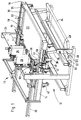
- the drilling table 10 has a frame 12 on that a number of horizontally arranged side members 14, 16 and cross members 18 carries at a height usual for worktops.
- the longitudinal and cross members 14, 16, 18 form a rectangular grid frame. Top sides of the longitudinal and cross members 14, 16, 18 are in one plane, they form a support surface 20 for placing one Workpiece plate 22, for example a natural stone or provided as a facade plate Ceramic plate.
- drilling machines 26 On a traverse 24, which is attached to the frame 12 above the work surface 20, are two drilling machines 26 or known drilling devices for manufacturing from undercut holes.
- the drilling machines 26 are in Transversely to the drilling table 10 displaceable and lockable. Using a hand lever 28 they can be lowered for drilling.
- rollers 32 rotatably mounted in roller rails 30, which in Are arranged in the longitudinal direction. Axes of rotation of the rollers 32 run parallel to the Cross members 18.
- the rollers 32 can be with a lifting device described below be raised and lowered. They are in a lowered processing position Rollers 32 lowered under the bearing surface 20 so that the workpiece plate 22 on the Support surface 20 rests. The rollers 32 are in a raised positioning position upwards over the bearing surface 20, so that the workpiece plate 22 from the Support surface 20 is lifted off and thereby in the longitudinal direction of the drilling table 10 is easy to move.
- the lifting device has a mechanical lever gear, which is operated with a foot lever 34 can be actuated:
- the foot lever 34 is about an axis running transversely to the drilling table 10 pivotally mounted on the base of the frame 12. On a front of the drilling table 10 can the foot lever 34 extending over the width of the drilling table 10 be trodden down.
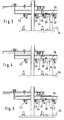
- the lifting device has a for locking in the raised positioning position Locking device in the form of a heart curve control shown in Figure 6:
- Locking device in the form of a heart curve control shown in Figure 6:
- One Cardiac trajectory 46 is sunk in a swivel plate 48, which is one Pin 50 on the frame 12 is pivotable.
- Intervening in the heart curve 46 Locking pin 52 which is fixedly attached to the tension strut 36 of the lifting device.
- Locking pin 52 is shown in Figure 6 in four different positions, of which the numbered positions III, IV, V of the processing position (Figure 3), the third Position ( Figure 4) and the positioning position ( Figure 5) correspond.
- the foot lever 34 is depressed, as a result of which the Pull strut 36 pulled down and the roller rails 30 from the lever arm 40 of the Angle lever 38 and the pivot lever 42 are pressed up. Of the The locking pin 52 of the tension strut 36 thereby moves in the heart curve 46 from position III in position IV. If the foot lever 34 is then released, the Locking pin 52 in the locked position V, in which it remains by itself, the tension strut 36 holds in a downward position and thereby the roller rails 30 in raised position locked. By stepping down again and Let go of the foot lever 34, the locking pin 52 does not reach the in Figure 6 numbered position back to position III, in which the roller rails 30 again in the processing position is lowered.
- the Swivel stops 54 are located in the direction of displacement of the workpiece plate 22 one after the other and are adjustable in the direction of displacement. You are in one Roll or displacement path of the workpiece plate 22 and can be by means of Swing the lifting device out of the sliding track: there is a pull rod 56 articulated on the lever arm 40 of the angle lever 38, which is connected via a swivel lever 58 a longitudinally extending square rod 60 is pivoted, on which the Swivel fittings 54 are non-rotatable and can be moved and locked in the longitudinal direction are attached.
- the pivotal movement of the square bar 60 is from a push rod 62 on Transfer the round tube 64 running transversely to the drilling table 10 (FIG. 8).
- the round tube 64 transfers the pivoting movement to a second square bar 66, the other on the other Side of the workpiece plate 22 is arranged and in the longitudinal direction of the drilling table 10 runs.
- the second square rod 66 pivots through the same angle as that Square bar 60 with opposite direction of rotation. He also wears a couple Swivel stops 54 so that the swivel stops 54 on both sides of the Workpiece plate 22 can be pivoted together out of their displacement path.
- the second square rod 66 can be adjusted in the transverse direction of the drilling table 10 Adaptation to a width of the workpiece plate 22.
- the left side member 14 On a (in the illustrated embodiment, the left) side member 14 is one Longitudinal guide 68 attached. On the opposite side is one in itself Known, acting in the manner of a vice vise 70 on the Support surface 20 of the drilling table 10 attached.
- the function of the drilling table 10 is as follows: For drilling a Series of workpiece plates 22 of the same size with matching borehole arrangement are the drilling machines 26 in the transverse direction at a certain distance from the Guide bar 68 set. Then the pivot stops 54 in Longitudinal direction on their square bars 60, 66 at a certain distance from the Drills 26 set.
- a workpiece plate 22 is placed on the support surface 20 so that it on the Guide bar 68 abuts.
- the foot lever 34 is depressed, so that the locking pin 52 of the tension strut 36 in the position IV and after releasing the foot lever 34 in the arrested position V arrives, in which it remains by itself.
- This will make the Roller rails 30 raised and the workpiece plate 22 from the support surface 20th lifted off so that they are free on the rollers 32 in the longitudinal direction of the drilling table 10 is movable.
- the workpiece plate 22 is up to the first pivot stops 54 moved backwards.
- the foot lever 34 is depressed and again released so that the locking pin 52 over the unnumbered position in the Position III arrives.
- the roller rails 30 are lowered and the workpiece plate 22 lies on the bearing surface 20.
- the workpiece plate 22 with the Tensioning device 70 can be tensioned against the guide bar 68. It is for drilling of the first pair of holes. After drilling the first pair of holes the tensioning device 70 is released and the foot lever 34 is depressed, so that the Latching pin 52 reaches position IV in the curve 46. Located in this position the drilling table 10 in its third position, the workpiece plate 22 is free slidably raised and the pivot stops 54 are off the track of Workpiece plate 22 swung out upwards. The workpiece plate 22 can move under the first swivel stops 54. Now the foot pedal 34 released, the locking pin 52 returns to the locked position V, in which it from remains itself. The drilling table 10 is in the positioning position.
- the workpiece plate 22 is still freely movable.
- the front Swivel stops 54 are spring-loaded on the workpiece plate 22, so that the Workpiece plate 22 can be moved below them until they reach the next Swing stops 54 abuts.
- the foot lever 34 is depressed again and released so that the locking pin 52 reaches position III, in which the Workpiece plate 22 rests on the bearing surface 20 and the next pair of holes can be drilled.
Landscapes
- Engineering & Computer Science (AREA)
- Mechanical Engineering (AREA)
- Drilling And Boring (AREA)
Applications Claiming Priority (2)
| Application Number | Priority Date | Filing Date | Title |
|---|---|---|---|
| DE29617447U | 1996-10-08 | ||
| DE29617447U DE29617447U1 (de) | 1996-10-08 | 1996-10-08 | Bohrtisch |
Publications (2)
| Publication Number | Publication Date |
|---|---|
| EP0835707A2 true EP0835707A2 (fr) | 1998-04-15 |
| EP0835707A3 EP0835707A3 (fr) | 1998-12-16 |
Family
ID=8030273
Family Applications (1)
| Application Number | Title | Priority Date | Filing Date |
|---|---|---|---|
| EP97116422A Withdrawn EP0835707A3 (fr) | 1996-10-08 | 1997-09-20 | Table de perçage |
Country Status (2)
| Country | Link |
|---|---|
| EP (1) | EP0835707A3 (fr) |
| DE (1) | DE29617447U1 (fr) |
Cited By (3)
| Publication number | Priority date | Publication date | Assignee | Title |
|---|---|---|---|---|
| EP1338375A2 (fr) * | 2002-02-20 | 2003-08-27 | Euromac S.p.A. | Table de support à faible coefficient de frottement pour poinçonneuse de tôle |
| CN106112046A (zh) * | 2016-08-03 | 2016-11-16 | 苏州市吴中区木渎晓云模具加工厂 | 阀体上盖加工线的钻孔加工装置 |
| CN114700524A (zh) * | 2022-04-25 | 2022-07-05 | 江西玖亚新建筑工程有限公司 | 一种装饰装修用防偏移打孔设备 |
Families Citing this family (3)
| Publication number | Priority date | Publication date | Assignee | Title |
|---|---|---|---|---|
| CN105665786A (zh) * | 2016-01-19 | 2016-06-15 | 苏州诚亭自动化设备有限公司 | 一种自动化打孔机 |
| CN105856338A (zh) * | 2016-06-14 | 2016-08-17 | 成都世纪达菲家具有限公司 | 一种用于木工电钻的辅助结构 |
| CN113482231B (zh) * | 2021-07-30 | 2022-12-09 | 山东洲盛建筑工程有限公司 | 一种装配式建筑模块及其加工设备 |
Citations (5)
| Publication number | Priority date | Publication date | Assignee | Title |
|---|---|---|---|---|
| DE2544480A1 (de) * | 1975-10-04 | 1977-04-14 | Zimmermann Erich | Vorrichtung zum ausbohren von natursteinplatten, insbesondere von treppenstufen aus naturstein |
| DE3526634A1 (de) * | 1985-07-25 | 1987-02-05 | Bachmann Elb Explosionsschutzg | Vorrichtung zum anheben und verschieben von werkzeugen oder werkstuecken auf einem aufspanntisch |
| EP0417475A1 (fr) * | 1989-09-12 | 1991-03-20 | Schunk Automation Gmbh | Station d'assemblage à transporteur pour porteurs de pièce |
| EP0436034A1 (fr) * | 1989-07-24 | 1991-07-10 | Kitamura Machinery Co., Ltd. | Changeur de palettes a commande manuelle |
| EP0445404A2 (fr) * | 1990-03-09 | 1991-09-11 | fischerwerke Artur Fischer GmbH & Co. KG | Dispositif de fabrication de trous forés avec chambrage |
Family Cites Families (1)
| Publication number | Priority date | Publication date | Assignee | Title |
|---|---|---|---|---|
| US4033216A (en) * | 1976-09-24 | 1977-07-05 | W. A. Whitney Corporation | Duplicating punch press with stylus control |
-
1996
- 1996-10-08 DE DE29617447U patent/DE29617447U1/de not_active Expired - Lifetime
-
1997
- 1997-09-20 EP EP97116422A patent/EP0835707A3/fr not_active Withdrawn
Patent Citations (5)
| Publication number | Priority date | Publication date | Assignee | Title |
|---|---|---|---|---|
| DE2544480A1 (de) * | 1975-10-04 | 1977-04-14 | Zimmermann Erich | Vorrichtung zum ausbohren von natursteinplatten, insbesondere von treppenstufen aus naturstein |
| DE3526634A1 (de) * | 1985-07-25 | 1987-02-05 | Bachmann Elb Explosionsschutzg | Vorrichtung zum anheben und verschieben von werkzeugen oder werkstuecken auf einem aufspanntisch |
| EP0436034A1 (fr) * | 1989-07-24 | 1991-07-10 | Kitamura Machinery Co., Ltd. | Changeur de palettes a commande manuelle |
| EP0417475A1 (fr) * | 1989-09-12 | 1991-03-20 | Schunk Automation Gmbh | Station d'assemblage à transporteur pour porteurs de pièce |
| EP0445404A2 (fr) * | 1990-03-09 | 1991-09-11 | fischerwerke Artur Fischer GmbH & Co. KG | Dispositif de fabrication de trous forés avec chambrage |
Cited By (6)
| Publication number | Priority date | Publication date | Assignee | Title |
|---|---|---|---|---|
| EP1338375A2 (fr) * | 2002-02-20 | 2003-08-27 | Euromac S.p.A. | Table de support à faible coefficient de frottement pour poinçonneuse de tôle |
| EP1338375A3 (fr) * | 2002-02-20 | 2004-02-04 | Euromac S.p.A. | Table de support à faible coefficient de frottement pour poinçonneuse de tôle |
| CN106112046A (zh) * | 2016-08-03 | 2016-11-16 | 苏州市吴中区木渎晓云模具加工厂 | 阀体上盖加工线的钻孔加工装置 |
| CN106112046B (zh) * | 2016-08-03 | 2018-03-16 | 陈斌 | 阀体上盖加工线的钻孔加工装置 |
| CN114700524A (zh) * | 2022-04-25 | 2022-07-05 | 江西玖亚新建筑工程有限公司 | 一种装饰装修用防偏移打孔设备 |
| CN114700524B (zh) * | 2022-04-25 | 2023-09-26 | 深圳中壹建设(集团)有限公司 | 一种装饰装修用防偏移打孔设备 |
Also Published As
| Publication number | Publication date |
|---|---|
| DE29617447U1 (de) | 1996-11-21 |
| EP0835707A3 (fr) | 1998-12-16 |
Similar Documents
| Publication | Publication Date | Title |
|---|---|---|
| DE4007449C1 (fr) | ||
| DE1683327B2 (de) | Verfahrbare trennwand | |
| DE3437092A1 (de) | Montagevorrichtung fuer fenster, tueren und dergleichen | |
| DE4437085C2 (de) | Presse mit einem Pressen- und Konsolentisch | |
| EP0835707A2 (fr) | Table de perçage | |
| CH645054A5 (en) | Board-trimming and board-dividing saw | |
| DD296124A5 (de) | Stoffdrueckereinrichtung fuer naehmaschinen | |
| DE3100163C2 (fr) | ||
| DE3817005C2 (de) | Schweißmaschine zur Herstellung von Rahmen | |
| DE3231313C2 (fr) | ||
| DE2813802C2 (de) | Vorrichtung zum Zuschneiden von Platten | |
| DE2546752B2 (de) | Betaetigungseinrichtung fuer zwei abwechselnd zwischen einer ersten und einer zweiten stellung bewegbare spurreisser | |
| DE862831C (de) | Maschine zur Herstellung von Knoepfen aus plattenfoermigem Werkstoff | |
| DE2813762C2 (de) | Vorrichtung zum Zuschneiden von Platten, wie Span-Sperrholzplatten und dergl. | |
| DE3022922A1 (de) | Blechschere | |
| DE4017093A1 (de) | Formatkreissaege | |
| DE271178C (fr) | ||
| DE4307928A1 (de) | Vorrichtung zum Formen von gekrümmten Bauteilen | |
| DE2712673A1 (de) | Stossmessermaschine | |
| DE2910097C2 (de) | Vorrichtung zum Fräsen von Entwässerungsschlitzen in ein Fensterprofil | |
| DE2706108C2 (de) | Verfahren und Einrichtung zur Lageänderung beweglicher Abschnitte in Bühnenböden | |
| DE2356250C2 (de) | Vorrichtung zur Herstellung von Zuschnitten | |
| EP1437196B1 (fr) | Dispositif pour l'usinage des profilés creux le long plusieurs faces | |
| DE2460741C3 (de) | Vorrichtung zum Ausrichten von zu besäumenden Brettern | |
| DE2316071B2 (de) | Haltevorrichtung für zahnärztliche Handstücke |
Legal Events
| Date | Code | Title | Description |
|---|---|---|---|
| PUAI | Public reference made under article 153(3) epc to a published international application that has entered the european phase |
Free format text: ORIGINAL CODE: 0009012 |
|
| AK | Designated contracting states |
Kind code of ref document: A2 Designated state(s): DE ES FR IT NL PT |
|
| AX | Request for extension of the european patent |
Free format text: AL;LT;LV;RO;SI |
|
| PUAL | Search report despatched |
Free format text: ORIGINAL CODE: 0009013 |
|
| AK | Designated contracting states |
Kind code of ref document: A3 Designated state(s): AT BE CH DE DK ES FI FR GB GR IE IT LI LU MC NL PT SE |
|
| AX | Request for extension of the european patent |
Free format text: AL;LT;LV;RO;SI |
|
| 17P | Request for examination filed |
Effective date: 19990503 |
|
| AKX | Designation fees paid |
Free format text: DE ES FR IT NL PT |
|
| STAA | Information on the status of an ep patent application or granted ep patent |
Free format text: STATUS: THE APPLICATION IS DEEMED TO BE WITHDRAWN |
|
| 18D | Application deemed to be withdrawn |
Effective date: 20050331 |