EP0831473A2 - Optische Informationsaufzeichnungsplatte - Google Patents
Optische Informationsaufzeichnungsplatte Download PDFInfo
- Publication number
- EP0831473A2 EP0831473A2 EP97116651A EP97116651A EP0831473A2 EP 0831473 A2 EP0831473 A2 EP 0831473A2 EP 97116651 A EP97116651 A EP 97116651A EP 97116651 A EP97116651 A EP 97116651A EP 0831473 A2 EP0831473 A2 EP 0831473A2
- Authority
- EP
- European Patent Office
- Prior art keywords
- disc
- layer
- substrate
- information
- recording
- Prior art date
- Legal status (The legal status is an assumption and is not a legal conclusion. Google has not performed a legal analysis and makes no representation as to the accuracy of the status listed.)
- Granted
Links
- 230000003287 optical effect Effects 0.000 title claims abstract description 45
- 239000000758 substrate Substances 0.000 claims abstract description 234
- 230000002093 peripheral effect Effects 0.000 claims abstract description 83
- 239000010410 layer Substances 0.000 claims description 267
- 239000011241 protective layer Substances 0.000 claims description 69
- 239000012790 adhesive layer Substances 0.000 claims description 57
- 238000000034 method Methods 0.000 claims description 16
- 239000000853 adhesive Substances 0.000 claims description 8
- 230000001070 adhesive effect Effects 0.000 claims description 8
- 238000012545 processing Methods 0.000 claims description 5
- 229920001084 poly(chloroprene) Polymers 0.000 claims description 4
- 229920002379 silicone rubber Polymers 0.000 claims description 3
- 239000004945 silicone rubber Substances 0.000 claims description 3
- 239000013013 elastic material Substances 0.000 claims description 2
- 239000011347 resin Substances 0.000 abstract description 31
- 229920005989 resin Polymers 0.000 abstract description 31
- 238000003860 storage Methods 0.000 abstract description 12
- 239000000975 dye Substances 0.000 description 46
- OKTJSMMVPCPJKN-UHFFFAOYSA-N Carbon Chemical compound [C] OKTJSMMVPCPJKN-UHFFFAOYSA-N 0.000 description 17
- 229910052799 carbon Inorganic materials 0.000 description 17
- 229920001971 elastomer Polymers 0.000 description 13
- 238000004519 manufacturing process Methods 0.000 description 12
- -1 polyethylene Polymers 0.000 description 11
- 230000001681 protective effect Effects 0.000 description 10
- 239000005060 rubber Substances 0.000 description 9
- 239000002131 composite material Substances 0.000 description 8
- 239000000463 material Substances 0.000 description 8
- 238000004528 spin coating Methods 0.000 description 8
- 239000000203 mixture Substances 0.000 description 7
- 238000003848 UV Light-Curing Methods 0.000 description 6
- 239000004417 polycarbonate Substances 0.000 description 6
- 229920000515 polycarbonate Polymers 0.000 description 6
- VYPSYNLAJGMNEJ-UHFFFAOYSA-N Silicium dioxide Chemical compound O=[Si]=O VYPSYNLAJGMNEJ-UHFFFAOYSA-N 0.000 description 5
- 239000004927 clay Substances 0.000 description 5
- 229920001577 copolymer Polymers 0.000 description 5
- 238000000926 separation method Methods 0.000 description 5
- 239000002344 surface layer Substances 0.000 description 5
- VTYYLEPIZMXCLO-UHFFFAOYSA-L Calcium carbonate Chemical compound [Ca+2].[O-]C([O-])=O VTYYLEPIZMXCLO-UHFFFAOYSA-L 0.000 description 4
- 230000015572 biosynthetic process Effects 0.000 description 4
- 238000000576 coating method Methods 0.000 description 4
- 239000000806 elastomer Substances 0.000 description 4
- 229910052751 metal Inorganic materials 0.000 description 4
- 239000002184 metal Substances 0.000 description 4
- 239000000178 monomer Substances 0.000 description 4
- NIXOWILDQLNWCW-UHFFFAOYSA-M Acrylate Chemical compound [O-]C(=O)C=C NIXOWILDQLNWCW-UHFFFAOYSA-M 0.000 description 3
- 239000004743 Polypropylene Substances 0.000 description 3
- 229910052782 aluminium Inorganic materials 0.000 description 3
- 238000011156 evaluation Methods 0.000 description 3
- 229920003049 isoprene rubber Polymers 0.000 description 3
- 238000000465 moulding Methods 0.000 description 3
- 229920000728 polyester Polymers 0.000 description 3
- 229920000098 polyolefin Polymers 0.000 description 3
- 229920001155 polypropylene Polymers 0.000 description 3
- 238000004544 sputter deposition Methods 0.000 description 3
- 229920003048 styrene butadiene rubber Polymers 0.000 description 3
- YELMWJNXDALKFE-UHFFFAOYSA-N 3h-imidazo[4,5-f]quinoxaline Chemical compound N1=CC=NC2=C(NC=N3)C3=CC=C21 YELMWJNXDALKFE-UHFFFAOYSA-N 0.000 description 2
- 239000004709 Chlorinated polyethylene Substances 0.000 description 2
- 244000043261 Hevea brasiliensis Species 0.000 description 2
- 229920000459 Nitrile rubber Polymers 0.000 description 2
- BPQQTUXANYXVAA-UHFFFAOYSA-N Orthosilicate Chemical compound [O-][Si]([O-])([O-])[O-] BPQQTUXANYXVAA-UHFFFAOYSA-N 0.000 description 2
- 239000005062 Polybutadiene Substances 0.000 description 2
- BZHJMEDXRYGGRV-UHFFFAOYSA-N Vinyl chloride Chemical compound ClC=C BZHJMEDXRYGGRV-UHFFFAOYSA-N 0.000 description 2
- UGZICOVULPINFH-UHFFFAOYSA-N acetic acid;butanoic acid Chemical compound CC(O)=O.CCCC(O)=O UGZICOVULPINFH-UHFFFAOYSA-N 0.000 description 2
- XECAHXYUAAWDEL-UHFFFAOYSA-N acrylonitrile butadiene styrene Chemical compound C=CC=C.C=CC#N.C=CC1=CC=CC=C1 XECAHXYUAAWDEL-UHFFFAOYSA-N 0.000 description 2
- 239000004676 acrylonitrile butadiene styrene Substances 0.000 description 2
- 229920000122 acrylonitrile butadiene styrene Polymers 0.000 description 2
- 239000004840 adhesive resin Substances 0.000 description 2
- 229920006223 adhesive resin Polymers 0.000 description 2
- 230000004888 barrier function Effects 0.000 description 2
- 239000011230 binding agent Substances 0.000 description 2
- 229910000019 calcium carbonate Inorganic materials 0.000 description 2
- 229920001727 cellulose butyrate Polymers 0.000 description 2
- 229910052804 chromium Inorganic materials 0.000 description 2
- 239000011248 coating agent Substances 0.000 description 2
- 229910052802 copper Inorganic materials 0.000 description 2
- 235000012489 doughnuts Nutrition 0.000 description 2
- 238000001125 extrusion Methods 0.000 description 2
- 239000003365 glass fiber Substances 0.000 description 2
- 229910052737 gold Inorganic materials 0.000 description 2
- 229920002681 hypalon Polymers 0.000 description 2
- 238000009863 impact test Methods 0.000 description 2
- 239000003999 initiator Substances 0.000 description 2
- QSHDDOUJBYECFT-UHFFFAOYSA-N mercury Chemical compound [Hg] QSHDDOUJBYECFT-UHFFFAOYSA-N 0.000 description 2
- 229910052753 mercury Inorganic materials 0.000 description 2
- 229920003052 natural elastomer Polymers 0.000 description 2
- 229920001194 natural rubber Polymers 0.000 description 2
- 229910052759 nickel Inorganic materials 0.000 description 2
- 239000001007 phthalocyanine dye Substances 0.000 description 2
- 229910052697 platinum Inorganic materials 0.000 description 2
- 229920003229 poly(methyl methacrylate) Polymers 0.000 description 2
- 229920002857 polybutadiene Polymers 0.000 description 2
- 229920000642 polymer Polymers 0.000 description 2
- 239000004926 polymethyl methacrylate Substances 0.000 description 2
- 239000004814 polyurethane Substances 0.000 description 2
- 229920000915 polyvinyl chloride Polymers 0.000 description 2
- 239000004800 polyvinyl chloride Substances 0.000 description 2
- 239000004576 sand Substances 0.000 description 2
- 229910052709 silver Inorganic materials 0.000 description 2
- 239000002904 solvent Substances 0.000 description 2
- 230000003746 surface roughness Effects 0.000 description 2
- ANRHNWWPFJCPAZ-UHFFFAOYSA-M thionine Chemical compound [Cl-].C1=CC(N)=CC2=[S+]C3=CC(N)=CC=C3N=C21 ANRHNWWPFJCPAZ-UHFFFAOYSA-M 0.000 description 2
- 238000001771 vacuum deposition Methods 0.000 description 2
- NBUKAOOFKZFCGD-UHFFFAOYSA-N 2,2,3,3-tetrafluoropropan-1-ol Chemical compound OCC(F)(F)C(F)F NBUKAOOFKZFCGD-UHFFFAOYSA-N 0.000 description 1
- SMZOUWXMTYCWNB-UHFFFAOYSA-N 2-(2-methoxy-5-methylphenyl)ethanamine Chemical compound COC1=CC=C(C)C=C1CCN SMZOUWXMTYCWNB-UHFFFAOYSA-N 0.000 description 1
- NIXOWILDQLNWCW-UHFFFAOYSA-N 2-Propenoic acid Natural products OC(=O)C=C NIXOWILDQLNWCW-UHFFFAOYSA-N 0.000 description 1
- MUZDXNQOSGWMJJ-UHFFFAOYSA-N 2-methylprop-2-enoic acid;prop-2-enoic acid Chemical compound OC(=O)C=C.CC(=C)C(O)=O MUZDXNQOSGWMJJ-UHFFFAOYSA-N 0.000 description 1
- PYSRRFNXTXNWCD-UHFFFAOYSA-N 3-(2-phenylethenyl)furan-2,5-dione Chemical compound O=C1OC(=O)C(C=CC=2C=CC=CC=2)=C1 PYSRRFNXTXNWCD-UHFFFAOYSA-N 0.000 description 1
- XURABDHWIADCPO-UHFFFAOYSA-N 4-prop-2-enylhepta-1,6-diene Chemical compound C=CCC(CC=C)CC=C XURABDHWIADCPO-UHFFFAOYSA-N 0.000 description 1
- 229920000178 Acrylic resin Polymers 0.000 description 1
- 239000004925 Acrylic resin Substances 0.000 description 1
- 239000004953 Aliphatic polyamide Substances 0.000 description 1
- DQEFEBPAPFSJLV-UHFFFAOYSA-N Cellulose propionate Chemical compound CCC(=O)OCC1OC(OC(=O)CC)C(OC(=O)CC)C(OC(=O)CC)C1OC1C(OC(=O)CC)C(OC(=O)CC)C(OC(=O)CC)C(COC(=O)CC)O1 DQEFEBPAPFSJLV-UHFFFAOYSA-N 0.000 description 1
- 229920002943 EPDM rubber Polymers 0.000 description 1
- 239000004593 Epoxy Substances 0.000 description 1
- 239000001856 Ethyl cellulose Substances 0.000 description 1
- ZZSNKZQZMQGXPY-UHFFFAOYSA-N Ethyl cellulose Chemical compound CCOCC1OC(OC)C(OCC)C(OCC)C1OC1C(O)C(O)C(OC)C(CO)O1 ZZSNKZQZMQGXPY-UHFFFAOYSA-N 0.000 description 1
- JOYRKODLDBILNP-UHFFFAOYSA-N Ethyl urethane Chemical compound CCOC(N)=O JOYRKODLDBILNP-UHFFFAOYSA-N 0.000 description 1
- 229920000181 Ethylene propylene rubber Polymers 0.000 description 1
- VHOQXEIFYTTXJU-UHFFFAOYSA-N Isobutylene-isoprene copolymer Chemical compound CC(C)=C.CC(=C)C=C VHOQXEIFYTTXJU-UHFFFAOYSA-N 0.000 description 1
- CERQOIWHTDAKMF-UHFFFAOYSA-N Methacrylic acid Chemical compound CC(=C)C(O)=O CERQOIWHTDAKMF-UHFFFAOYSA-N 0.000 description 1
- CNCOEDDPFOAUMB-UHFFFAOYSA-N N-Methylolacrylamide Chemical compound OCNC(=O)C=C CNCOEDDPFOAUMB-UHFFFAOYSA-N 0.000 description 1
- 229930192627 Naphthoquinone Natural products 0.000 description 1
- 239000000020 Nitrocellulose Substances 0.000 description 1
- 229920002292 Nylon 6 Polymers 0.000 description 1
- 239000004698 Polyethylene Substances 0.000 description 1
- 239000004642 Polyimide Substances 0.000 description 1
- 239000004372 Polyvinyl alcohol Substances 0.000 description 1
- GOOHAUXETOMSMM-UHFFFAOYSA-N Propylene oxide Chemical compound CC1CO1 GOOHAUXETOMSMM-UHFFFAOYSA-N 0.000 description 1
- 229920000147 Styrene maleic anhydride Polymers 0.000 description 1
- 239000002174 Styrene-butadiene Substances 0.000 description 1
- 229920006311 Urethane elastomer Polymers 0.000 description 1
- XTXRWKRVRITETP-UHFFFAOYSA-N Vinyl acetate Chemical compound CC(=O)OC=C XTXRWKRVRITETP-UHFFFAOYSA-N 0.000 description 1
- 150000001252 acrylic acid derivatives Chemical class 0.000 description 1
- 229920003231 aliphatic polyamide Polymers 0.000 description 1
- XAGFODPZIPBFFR-UHFFFAOYSA-N aluminium Chemical compound [Al] XAGFODPZIPBFFR-UHFFFAOYSA-N 0.000 description 1
- PNEYBMLMFCGWSK-UHFFFAOYSA-N aluminium oxide Inorganic materials [O-2].[O-2].[O-2].[Al+3].[Al+3] PNEYBMLMFCGWSK-UHFFFAOYSA-N 0.000 description 1
- 239000001000 anthraquinone dye Substances 0.000 description 1
- 229910052797 bismuth Inorganic materials 0.000 description 1
- 229910052793 cadmium Inorganic materials 0.000 description 1
- 229920002301 cellulose acetate Polymers 0.000 description 1
- 229920006218 cellulose propionate Polymers 0.000 description 1
- 239000012461 cellulose resin Substances 0.000 description 1
- UUAGAQFQZIEFAH-UHFFFAOYSA-N chlorotrifluoroethylene Chemical compound FC(F)=C(F)Cl UUAGAQFQZIEFAH-UHFFFAOYSA-N 0.000 description 1
- 229910052681 coesite Inorganic materials 0.000 description 1
- 238000007796 conventional method Methods 0.000 description 1
- 229910052593 corundum Inorganic materials 0.000 description 1
- 229910052906 cristobalite Inorganic materials 0.000 description 1
- 238000005137 deposition process Methods 0.000 description 1
- 150000005690 diesters Chemical class 0.000 description 1
- 238000001035 drying Methods 0.000 description 1
- 229920005558 epichlorohydrin rubber Polymers 0.000 description 1
- 239000003822 epoxy resin Substances 0.000 description 1
- 229920001249 ethyl cellulose Polymers 0.000 description 1
- 235000019325 ethyl cellulose Nutrition 0.000 description 1
- 229920000840 ethylene tetrafluoroethylene copolymer Polymers 0.000 description 1
- 125000001153 fluoro group Chemical group F* 0.000 description 1
- 238000010528 free radical solution polymerization reaction Methods 0.000 description 1
- 229910052733 gallium Inorganic materials 0.000 description 1
- 229910052732 germanium Inorganic materials 0.000 description 1
- 229910052735 hafnium Inorganic materials 0.000 description 1
- 229910052738 indium Inorganic materials 0.000 description 1
- 239000001013 indophenol dye Substances 0.000 description 1
- 229910001506 inorganic fluoride Inorganic materials 0.000 description 1
- 229910010272 inorganic material Inorganic materials 0.000 description 1
- 239000011147 inorganic material Substances 0.000 description 1
- 229910052809 inorganic oxide Inorganic materials 0.000 description 1
- 238000007733 ion plating Methods 0.000 description 1
- 229910052741 iridium Inorganic materials 0.000 description 1
- 229910052742 iron Inorganic materials 0.000 description 1
- 229910001635 magnesium fluoride Inorganic materials 0.000 description 1
- 229910052748 manganese Inorganic materials 0.000 description 1
- 238000005259 measurement Methods 0.000 description 1
- DZVCFNFOPIZQKX-LTHRDKTGSA-M merocyanine Chemical compound [Na+].O=C1N(CCCC)C(=O)N(CCCC)C(=O)C1=C\C=C\C=C/1N(CCCS([O-])(=O)=O)C2=CC=CC=C2O\1 DZVCFNFOPIZQKX-LTHRDKTGSA-M 0.000 description 1
- 239000000434 metal complex dye Substances 0.000 description 1
- 229910001092 metal group alloy Inorganic materials 0.000 description 1
- 150000002739 metals Chemical class 0.000 description 1
- 229920003145 methacrylic acid copolymer Polymers 0.000 description 1
- 229940117841 methacrylic acid copolymer Drugs 0.000 description 1
- 229910052750 molybdenum Inorganic materials 0.000 description 1
- 150000002791 naphthoquinones Chemical class 0.000 description 1
- 229910052758 niobium Inorganic materials 0.000 description 1
- 229920001220 nitrocellulos Polymers 0.000 description 1
- 150000002832 nitroso derivatives Chemical class 0.000 description 1
- 229910052763 palladium Inorganic materials 0.000 description 1
- 229920000647 polyepoxide Polymers 0.000 description 1
- 229920000573 polyethylene Polymers 0.000 description 1
- 229920001721 polyimide Polymers 0.000 description 1
- 229920005596 polymer binder Polymers 0.000 description 1
- 239000002491 polymer binding agent Substances 0.000 description 1
- 239000002861 polymer material Substances 0.000 description 1
- 229920001021 polysulfide Polymers 0.000 description 1
- 239000005077 polysulfide Substances 0.000 description 1
- 150000008117 polysulfides Polymers 0.000 description 1
- 229920002635 polyurethane Polymers 0.000 description 1
- 229920002451 polyvinyl alcohol Polymers 0.000 description 1
- 239000000843 powder Substances 0.000 description 1
- WVIICGIFSIBFOG-UHFFFAOYSA-N pyrylium Chemical compound C1=CC=[O+]C=C1 WVIICGIFSIBFOG-UHFFFAOYSA-N 0.000 description 1
- 229910052702 rhenium Inorganic materials 0.000 description 1
- 229910052703 rhodium Inorganic materials 0.000 description 1
- 229910052707 ruthenium Inorganic materials 0.000 description 1
- 230000035939 shock Effects 0.000 description 1
- 229910052710 silicon Inorganic materials 0.000 description 1
- 239000000377 silicon dioxide Substances 0.000 description 1
- 238000001228 spectrum Methods 0.000 description 1
- 229910052682 stishovite Inorganic materials 0.000 description 1
- 239000000454 talc Substances 0.000 description 1
- 229910052623 talc Inorganic materials 0.000 description 1
- 229910052715 tantalum Inorganic materials 0.000 description 1
- 229920001169 thermoplastic Polymers 0.000 description 1
- 229920005992 thermoplastic resin Polymers 0.000 description 1
- 239000004416 thermosoftening plastic Substances 0.000 description 1
- OKYDCMQQLGECPI-UHFFFAOYSA-N thiopyrylium Chemical compound C1=CC=[S+]C=C1 OKYDCMQQLGECPI-UHFFFAOYSA-N 0.000 description 1
- 229910052719 titanium Inorganic materials 0.000 description 1
- 229910052905 tridymite Inorganic materials 0.000 description 1
- 150000005691 triesters Chemical class 0.000 description 1
- AAAQKTZKLRYKHR-UHFFFAOYSA-N triphenylmethane Chemical compound C1=CC=CC=C1C(C=1C=CC=CC=1)C1=CC=CC=C1 AAAQKTZKLRYKHR-UHFFFAOYSA-N 0.000 description 1
- 229910052721 tungsten Inorganic materials 0.000 description 1
- 229910052720 vanadium Inorganic materials 0.000 description 1
- 238000005406 washing Methods 0.000 description 1
- 229910001845 yogo sapphire Inorganic materials 0.000 description 1
- 229910052727 yttrium Inorganic materials 0.000 description 1
- 229910052725 zinc Inorganic materials 0.000 description 1
Images


Classifications
-
- G—PHYSICS
- G11—INFORMATION STORAGE
- G11B—INFORMATION STORAGE BASED ON RELATIVE MOVEMENT BETWEEN RECORD CARRIER AND TRANSDUCER
- G11B7/00—Recording or reproducing by optical means, e.g. recording using a thermal beam of optical radiation by modifying optical properties or the physical structure, reproducing using an optical beam at lower power by sensing optical properties; Record carriers therefor
- G11B7/24—Record carriers characterised by shape, structure or physical properties, or by the selection of the material
- G11B7/26—Apparatus or processes specially adapted for the manufacture of record carriers
-
- Y—GENERAL TAGGING OF NEW TECHNOLOGICAL DEVELOPMENTS; GENERAL TAGGING OF CROSS-SECTIONAL TECHNOLOGIES SPANNING OVER SEVERAL SECTIONS OF THE IPC; TECHNICAL SUBJECTS COVERED BY FORMER USPC CROSS-REFERENCE ART COLLECTIONS [XRACs] AND DIGESTS
- Y10—TECHNICAL SUBJECTS COVERED BY FORMER USPC
- Y10S—TECHNICAL SUBJECTS COVERED BY FORMER USPC CROSS-REFERENCE ART COLLECTIONS [XRACs] AND DIGESTS
- Y10S428/00—Stock material or miscellaneous articles
- Y10S428/913—Material designed to be responsive to temperature, light, moisture
-
- Y—GENERAL TAGGING OF NEW TECHNOLOGICAL DEVELOPMENTS; GENERAL TAGGING OF CROSS-SECTIONAL TECHNOLOGIES SPANNING OVER SEVERAL SECTIONS OF THE IPC; TECHNICAL SUBJECTS COVERED BY FORMER USPC CROSS-REFERENCE ART COLLECTIONS [XRACs] AND DIGESTS
- Y10—TECHNICAL SUBJECTS COVERED BY FORMER USPC
- Y10S—TECHNICAL SUBJECTS COVERED BY FORMER USPC CROSS-REFERENCE ART COLLECTIONS [XRACs] AND DIGESTS
- Y10S430/00—Radiation imagery chemistry: process, composition, or product thereof
- Y10S430/146—Laser beam
-
- Y—GENERAL TAGGING OF NEW TECHNOLOGICAL DEVELOPMENTS; GENERAL TAGGING OF CROSS-SECTIONAL TECHNOLOGIES SPANNING OVER SEVERAL SECTIONS OF THE IPC; TECHNICAL SUBJECTS COVERED BY FORMER USPC CROSS-REFERENCE ART COLLECTIONS [XRACs] AND DIGESTS
- Y10—TECHNICAL SUBJECTS COVERED BY FORMER USPC
- Y10T—TECHNICAL SUBJECTS COVERED BY FORMER US CLASSIFICATION
- Y10T428/00—Stock material or miscellaneous articles
- Y10T428/21—Circular sheet or circular blank
-
- Y—GENERAL TAGGING OF NEW TECHNOLOGICAL DEVELOPMENTS; GENERAL TAGGING OF CROSS-SECTIONAL TECHNOLOGIES SPANNING OVER SEVERAL SECTIONS OF THE IPC; TECHNICAL SUBJECTS COVERED BY FORMER USPC CROSS-REFERENCE ART COLLECTIONS [XRACs] AND DIGESTS
- Y10—TECHNICAL SUBJECTS COVERED BY FORMER USPC
- Y10T—TECHNICAL SUBJECTS COVERED BY FORMER US CLASSIFICATION
- Y10T428/00—Stock material or miscellaneous articles
- Y10T428/31504—Composite [nonstructural laminate]
- Y10T428/31678—Of metal
Definitions
- the present invention relates to an optical information recording disc, an apparatus for preparing an optical information recording disc, and a process for preparing an optical information recording disc.
- the invention relates to an optical information recording disc of DVD (Digital Video Disc) type.
- DVD Digital Video Disc
- the information recording discs of DVD type are classified into DVD-ROM (for read-out only), DVD-R (in which additional information is recordable), and DVD-RAM (in which a recorded information is rewritable).
- the information recording disc of DVD type has a sandwich structure.
- it comprises a pair of substrate discs having an information recorded layer from which the information is readable by applying thereto a laser beam or an information recordable layer in which an information is recordable by applying thereto a laser beam or comprises a substrate disc having an information recorded layer from which the information is readable by applying thereto a laser beam or an information recordable layer in which an information is recordable by applying thereto a laser beam and a disc plate.
- the pair of substrates or the set of substrate and disc plate is combined using an adhesive layer under the condition that the information recorded layer or information recordable layer is placed between them.
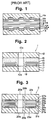
- Nikkei Electronics, No. 630 (1995, published Nihon Keizai Shimbunsha, namely, Japan Economic Journal), Specific Edition for "Optical Disc”, as well as Nikkei New Media, Specific Edition for "DVD” (1995, published Nihon Keizai Shimbunsha) illustrate a schematic structure of a representative optical information recording disc of DVD-R type, which is shown in Fig. 1 of Drawings attached to this specification.
- the representative information recording disc of DVD-R type of Fig. 1 comprises a pair of substrate discs 1a, 1b having a pre-groove for tracking, information recordable layers 2a, 2b placed on the substrate discs 1a, 1b, respectively, laser beam reflective layers 3a, 3b placed on the information recordable layers 2a, 2b, respectively, protective layers 4a, 4b, placed on the reflective layers 3a, 3b, respectively, and an adhesive layer 5 combining the protective layer 4a and the protective layer 4b.
- This information recording disc is produced by combining a pair of substrate discs 1a, 1b which are provided thereon with the information recording layer 2a, 2b, the reflective layer 3a, 3b, and the protective layer 4a, 4b, using an adhesive material 5.
- the present inventor has studied the optical information recording disc of DVD-type and has noticed that the information recording disc of DVD-type sometimes shows poor mechanical strength as well as poor storage stability.
- a further study of the inventor has revealed that the poor mechanical strength and poor storage stability are caused by partial peeling of the edges of the substrates from the assembled recording disc structure. The peeling is sometimes observed between the substrate and the protective layer.
- the recording layer generally comprises a dye and, possibly, a small amount of a binder, and therefore, it has low cohesion strength.
- the bonding strength between the reflective layer which is generally made of metal and the protective layer which is generally made of organic resin is low. Accordingly, the substrate disc easily separates from the protective layer at their outer peripheral ends when the information disc encounters physical shock or is stored for a long period under severe surrounding conditions. Particularly, if the substrate disc has a fin or flash at its outer or inner peripheral end, the separation occurs more easily when the information disc is brought into contact with other information disc or any other materials.
- the present invention has an object to provide an optical information recording disc showing an improved mechanical strength and an improved storage stability.
- the invention has a specific object to provide of an optical information recording disc of DVD-type having an improved mechanical strength and an improved storage stability.
- the present invention resides in an optical information recording disc comprising a pair of substrate discs which have a center hole and which are provided thereon with a recording layer, a reflective layer and a protective layer overlaid in order, the substrate discs being combined via an adhesive layer to place their protective layers between them, or comprising a substrate disc which has a center hole and which is provided thereon with a recording layer, a reflective layer and a protective layer overlaid in order and a disc plate, the substrate disc and the disc plate being combined via an adhesive layer to place the protective layer between them, wherein both the recording layer and reflective layer are retracted from the outer peripheral end of the substrate disc so that the substrate disc is exposed in the retracted area and the protective layer is kept in contact with the substrate disc in the exposed area.
- both the recording layer and reflective layer are further retracted from the peripheral end of the center hole so that the substrate disc is exposed in thus retracted area and the protective layer is kept in contact with the substrate disc in thus exposed area. Further, it is preferred that the adhesive layer is also kept in contact with the substrate disc in the exposed area.
- the information recording layer preferably is a dye layer.
- the invention resides in an optical information recording disc comprising a pair of substrate discs which have a center hole and which are provided thereon with a recording layer, a reflective layer and a protective layer overlaid in order, the substrate discs being combined via an adhesive layer to place their protective layers between them, or comprising a substrate disc which has a center hole and which is provided thereon with a recording layer, a reflective layer and a protective layer overlaid in order and a disc plate, the substrate disc and the disc plate being combined via an adhesive layer to place the protective layer between them, wherein the substrate disc is processed at its outer peripheral end to form an enlarged surface area and the reflective layer is retracted from the outer peripheral end of the substrate.
- both the recording layer and reflective layer are preferably retracted from the outer peripheral end of the substrate disc so that the substrate disc is exposed in the retracted area and the protective layer is kept in contact with the substrate disc in the exposed area.
- the substrate disc is further processed at its inner peripheral end to form an enlarged surface area, both the recording layer and reflective layer are further retracted from the inner peripheral end so that the substrate disc is exposed in thus retracted area, and the protective layer is kept in contact with the substrate disc in thus exposed area.
- the adhesive layer is also kept in contact with the substrate disc in the exposed area.
- Thee processing for forming the enlarged surface area has been performed preferably by roughing or chamfering the outer peripheral end of the substrate disc.
- the recording layer preferably is a dye layer.
- the invention resides in an optical information recording disc comprising a pair of substrate discs which have a center hole and which are provided thereon with a recording layer and a reflective layer overlaid in order, the substrate discs being combined via an adhesive layer to place their reflective layers between them, or comprising a substrate disc which has a center hole and which is provided thereon with a recording layer and a reflective layer overlaid in order and a disc plate, the substrate disc and the disc plate being combined via an adhesive layer to place the reflective layer between them, wherein both the recording layer and reflective layer are retracted from the outer peripheral end of the substrate disc so that the substrate disc is exposed in the retracted area and the adhesive layer is kept in contact with the substrate disc in the exposed area.
- both the recording layer and reflective layer are further retracted from the peripheral end of the center hole so that the substrate disc is exposed in thus retracted area and the adhesive is kept in contact with the substrate disc in thus exposed area.
- the recording layer preferably is a dye layer.
- the invention resides in an optical information recording disc comprising a pair of substrate discs which have a center hole and which are provided thereon with a recording layer and a reflective layer overlaid in order, the substrate discs being combined via an adhesive layer to place their reflective layers between them, or comprising a substrate disc which has a center hole and which is provided thereon with a recording layer and a reflective layer overlaid in order and a disc plate, the substrate disc and the disc plate being combined via an adhesive layer to place the reflective layer between them, wherein the substrate disc having is processed at its outer peripheral end to form an enlarged surface area and the reflective layer is retracted from the outer peripheral end of the substrate.
- both the recording layer and reflective layer are retracted from the outer peripheral end of the substrate disc so that the substrate disc is exposed in the retracted area and the adhesive is kept in contact with the substrate disc in the exposed area.
- the substrate disc is further processed at its inner peripheral end to form an enlarged surface area, both the recording layer and reflective layer are further retracted from the inner peripheral end so that the substrate disc is exposed in thus retracted area and the adhesive layer is kept in contact with the substrate disc in thus exposed area.
- the adhesive layer is also kept in contact with the substrate disc in the exposed area.
- the processing for forming the enlarged surface area has been performed preferably by roughing or chamfering the outer peripheral end of the substrate disc.
- the recording layer preferably s a dye layer.
- the invention resides in an apparatus for combining a pair of substrate discs having an information recorded layer from which the information is readable by applying thereto a laser beam or an information recordable layer in which an information is recordable by applying thereto a laser beam or combining a substrate disc having an information recorded layer from which the information is readable by applying thereto a laser beam or an information recordable layer in which an information is recordable by applying thereto a laser beam and a disc plate using an adhesive layer under the condition that the information recorded layer or information recordable layer is placed between them, to prepare an optical information recording disc, comprising at least one pressure disc plate which has an effective pressure diameter smaller than the diameter of the substrate disc and that of the disc plate.
- the above-mentioned apparatus preferably comprises a pair of pressure disc plates which have an effective pressure diameter smaller than the diameter of the substrate disc and that of the disc plate. It is preferred that the effective pressure diameter of the pressure disc plate is 90% to 98% (preferably 92% to 98%, more preferably 95% to 98%) of the diameter of the substrate disc and that of the disc plate. It is further preferred that the substrate disc and the disc plate diameter have a center hole and the diameter of the center hole of the pressure disc plate is larger than the diameter of the center hole of the substrate disc and that of the disc plate, preferably 1.01 to 1.1 times, more preferably 1.02 to 1.08 times.
- the invention resides in a process for combining a pair of substrate discs having an information recorded layer from which the information is readable by applying thereto a laser beam or an information recordable layer in which an information is recordable by applying thereto a laser beam or combining a substrate disc having an information recorded layer from which the information is readable by applying thereto a laser beam or an information recordable layer in which an information is recordable by applying thereto a laser beam and a disc plate using an adhesive layer under the condition that the information recorded layer or information recordable layer is placed between them, utilizing a pair of pressure disc plates which have an effective pressure diameter smaller than the diameter of the substrate disc and that of the disc plate.
- the invention resides in an apparatus for combining a pair of substrate discs having an information recorded layer from which the information is readable by applying thereto a laser beam or an information recordable layer in which an information is recordable by applying thereto a laser beam or combining a substrate disc having an information recorded layer from which the information is readable by applying thereto a laser beam or an information recordable layer in which an information is recordable by applying thereto a laser beam and a disc plate using an adhesive layer under the condition that the information recorded layer or information recordable layer is placed between them, comprising at least one pressure disc plate which has a surface having a hardness less than the hardness of the substrate disc and that of the disc plate.
- the above-mentioned apparatus preferably comprises a pair of pressure disc plates which have a surface having a hardness less than the hardness of the substrate disc and that of the disc plate.
- the hardness of the surface of the pressure disc plate preferably is in the range of 10% to 80% of the hardness of the substrate disc and that of the disc plate, in which the hardness is expressed in terms of Rockwell hardness.
- the surface of the pressure disc plate is preferably made of elastic material such as silicone rubber or chloroprene rubber.
- the invention resides in a process for combining a pair of substrate discs having an information recorded layer from which the information is readable by applying thereto a laser beam or an information recordable layer in which an information is recordable by applying thereto a laser beam or combining a substrate disc having an information recorded layer from which the information is readable by applying thereto a laser beam or an information recordable layer in which an information is recordable by applying thereto a laser beam and a disc plate using an adhesive layer under the condition that the information recorded layer or information recordable layer is placed between them, utilizing a pair of pressure disc plates which have a surface having a hardness less than the hardness of the substrate disc and that of the disc plate.
- Fig. 1 illustrates a schematic view of a known optical information recording disc of DVD-R type.
- Fig. 2 illustrates one example of the preferred structures of the information recording disc of the invention.
- Fig. 3 illustrates another example of the preferred structures of the information recording disc (symmetric type) of the invention.
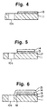
- Figs. 4 to 7 schematically illustrate a process for preparing the information recording disc of Fig. 2.
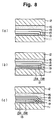
- Fig. 8 illustrates a few variations of the characteristic structure of the information recording disc of Fig. 2.
- Fig. 9 illustrates a further example of the optical information recording disc of the invention.
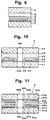
- Figs. 10 to 11 illustrate further examples of the optical information recording disc of the invention.
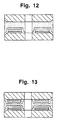
- Figs. 12 to 13 illustrate further examples of the optical information recording disc of the invention.
- Figs. 14 to 16 illustrate a process for preparing the information recording disc of Fig. 12.
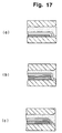
- Fig. 17 illustrates a few variations of the characteristic structure of the information recording disc of Fig. 12.
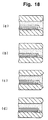
- Fig. 18 illustrates other variations of the characteristic structure of the information recording disc of Fig. 12.
- Fig. 19 illustrates other variations of the characteristic structure of the information recording disc of Fig. 12.
- Fig. 20 illustrates other variations of the characteristic structure of the information recording disc of Fig. 12.
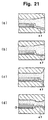
- Fig. 21 illustrates other variations of the characteristic structure of the information recording disc of Fig. 12.
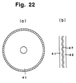
- Fig. 22 illustrates other variation of the characteristic structure of the information recording disc of the invention.
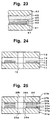
- Fig. 23 illustrates s further example of the optical information recording disc of the invention, in which no protective layer is provided.
- Figs. 24 to 25 illustrate further examples of the optical information recording disc of the invention which have no protective layer.
- Fig. 26 illustrates the protective layer-omitting versions of Fig. 8.
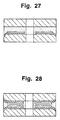
- Figs. 27 and 28 illustrate the protective layer-omitting versions of Figs. 10 and 11, respectively.
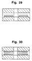
- Figs. 29 and 30 illustrate the protective layer-omitting versions of Figs. 12 and 13, respectively.
- Figs. 31 to 38 illustrate the specifically designed apparatus which are favorably employable for preparing the information recording disc of the invention or the conventional information recording disc.
- optical information recording disc of the invention is further described below.
- the optical information recording disc of the invention comprises a pair of substrate discs which have a center hole and which are provided thereon with a recording layer and a reflective layer (optionally, and a protective layer) overlaid in order, the substrate discs being combined via an adhesive layer to place their recording layers and reflective layers between them.
- One of the substrate disc having a center hole and being provided thereon with a recording layer and a reflective layer (optionally, and a protective layer) can be replaced with a disc plate which generally is the same as the substrate disc per se .
- the substrate disc (or disc plate) can be made of acrylic resin, vinyl chloride resin such as polyvinyl chloride or a copolymer of vinyl chloride and other monomer, epoxy resin, polycarbonate, amorphous polyolefin, or polyester. Other polymers can be employed. Preferred are polycarbonate, polyolefin and cell-cast polymethyl methacrylate.
- a subbing layer can be provided for improving the surface smoothness, adhesion conditions, keeping the recording layer from the substrate disc, or for other reasons.
- the subbing layer can be made of polymethyl methacrylate, acrylic acid-methacrylic acid copolymer, styrene-maleic anhydride copolymer, polyvinyl alcohol, N-methylolacrylamide, styrene-vinyltoluene copolymer, chlorosulfonated polyethylene, nitrocellulose, polyvinyl chloride, chlorinated polyolefin, polyester, polyimide, vinyl acetate, vinyl chloride copolymer, polyethylene, polypropylene, polycarbonate or other polymer, or inorganic material such as an inorganic oxide (e.g., SiO 2 or Al 2 O 3 ) or an inorganic fluoride (e.g., MgF 2 ).
- the subbing layer can be formed on the substrate disc using a conventional coating method such as spin coat
- a pregroove or pre-pit On the substrate disc or the subbing layer, a pregroove or pre-pit can be formed. Otherwise, a pregroove or pre-pit forming layer on which the pregroove or pre-pit is to be formed can be placed on the substrate disc or the subbing layer.
- the pre-groove or pre-pit forming layer can be made of a mixture of a monomer or oligomer of a monoester, diester, triester or tetraester of acrylic acid and a photopolymerization initiator, utilizing a conventional method.
- the information recording layer is preferably made of a dye.
- a small amount of a polymer binder can be incorporated into the recording layer.
- the dyes include cyanine dyes, phthalocyanine dyes, imidazoquinoxaline dyes, pyrylium dyes, thiopyrylium dyes, azulenium dyes, squalilium dyes, metal complex dyes such as Ni complex dyes and Cr complex dyes, naphthoquinone dyes, anthraquinone dyes, indophenol dyes, merocyanine dyes, oxonol dyes, indoaniline dyes, triphenylmethane dyes, triallylmethane dyes, aluminum-containing dyes, diimmonium dyes, and nitroso compounds.
- Preferred are cyanine dyes, phthalocyanine dyes, azulenium dyes, squalilium dyes, oxonol dyes, and imid
- the dye-containing information recording layer can be formed by coating a solution of a dye (and a binder, if necessary) in a solvent on the substrate disc or the subbing layer, and drying the coated layer.
- the information recording layer generally has a thickness of 10 to 550 nm.
- the recording layer can be composed of two or more dye-containing layers.
- an intermediate layer (barrier layer) can be placed between the adjacent dye-containing layers.
- the intermediate layer can be prepared by using a resin such as one described for the subbing layer.
- the intermediate layer generally has a thickness of 1 to 100 ⁇ m.
- the reflective layer is made of material which shows a high reflectance to a laser beam, such as metal or semi-metal.
- the reflective materials include Mg, Se, Y, Ti, Hf, V, Nb, Ta, Cr, Mo, W, Mn, Re, Fe, Co, Ni, Ru, Rh, Pd, Ir, Pt, Cu, Ag, Au, Zn, Cd, Al, Ga, In, Si, Ge, Te, Pb, Po, Sn and Bi.
- Preferred are Au, Ag, Cu, Pt, Al, Cr and Ni. Most preferred is Au.
- These metals can be employed singly or in combination. For instance, a metal alloy can be employed.
- the reflective layer generally has a thickness of 10 to 200 nm.
- the reflective layer is then coated with a protective layer.
- the protective layer can be made of a thermoplastic resin, a heat curable resin, a UV (ultraviolet) curable resin, or a mixture thereof.
- the UV curable resin is preferred.
- examples of the UV curable resins include oligomers of (meth)acrylates such as urethane (meth)acrylate, epoxy (meth)acrylate and polyester (meth)acrylate, and monomers such as (meth)acrylic acid ester.
- a photopolymerization initiator can be employed in combination with these oligomers and monomers.
- the protective layer generally has a thickness of 0.1 to 100 ⁇ m, preferably 1 to 15 ⁇ m.
- the provision of the protective layer may be omitted.
- the adhesive layer which is employed for combining a pair of the above-prepared composites or the composite with a simple substrate disc (i.e., disc plate) can be made of an adhesive resin.
- the adhesive resin can be the resin described above for the protective resin.
- the UV curable resin is preferably employed.
- the adhesive layer generally has a mean thickness of 0.1 to 100 ⁇ m, preferably 20 to 80 ⁇ m, most preferably 30 to 70 ⁇ m.
- the information recording disc 1 is composed of two resinous substrate discs 11, 12 (the substrate disc 12 may be referred to as "disc plate") which have center holes 10a, 10b, respectively and in which the substrate disc 11 is provided thereon with a recording layer 13 and a reflective layer 14 (both are retracted from the outer and inner peripheral edges to leave areas 17, 18 in which the surface of the substrate disc 11 is exposed), and further a protective resin layer 15 which is coated over the reflective layer 14 and is in contact with the exposed areas 17, 18, and an adhesive layer 16.
- the protective layer 15 is in contact with the resinous substrate disc 11 in the outer and inner peripheral exposed area 17, 18. Therefore, the protective layer 15 is firmly bonded to the substrate disc 11.
- the bonding between the protective layer 15 and the adhesive layer 16 is naturally firm, and the bonding between the adhesive layer 16 and the resinous substrate disc 12 is also firm. Therefore, the information recording disc of Fig. 2 has a high mechanical strength.
- Fig. 3 illustrates another example of the preferred structures of the invention.
- the information recording disc 2 is composed of two resinous substrate discs 21a, 21b which have center holes 20a, 20b, respectively and in which the substrate discs 21a, 21b are provided thereon with a recording layer 23a, 23b and a reflective layer 24a, 24b (both are retracted from the outer and inner peripheral edges to leave areas 27a, 27b, 28a, 28b in which the surfaces of the substrate discs 21a, 21b are exposed), and further a protective resin layer 25a, 25b which is coated over the reflective layer 24a, 24b and is in contact with the exposed areas 27a, 27b, 28a, 28b, and an adhesive layer 26.
- the protective layers 25a, 25b are in contact with the resinous substrate discs 21a, 21b, respectively, in the outer and inner peripheral exposed area 27a, 27b, 28a, 28b. Therefore, the protective layers 25a, 25b are firmly bonded to the substrate discs 21a, 21b, respectively.
- the bonding between the protective layer 25a, 25b and the adhesive layer 26a, 26b is naturally firm. Therefore, the information recording disc of Fig. 3 also has a high mechanical strength.
- Figs. 4 to 7 are given to illustrate a process for preparing the information recording disc of Fig. 2.
- a dye solution is coated on a substrate disc 11 (having a center hole 10a) by known spin coating to form a dye-containing recording layer 13.
- the inner edge of the recording layer 13 can be easily formed apart from the edge of the center hole 10a, as is shown in Fig. 4.
- the outer peripheral edge area 17 of the substrate disc 11 is exposed by removing the dye-containing recording layer 13 at that area 17.
- the removal of the outer peripheral area can be performed by washing out the recording layer in that area using an appropriate solvent.
- the removal of a part of the recording layer can be performed simultaneously with the formation of the recording layer.
- the removal of a part of the recording layer can be performed after the reflective layer is placed on the recording layer.
- the method for removing the dye-containing recording layer in the outer peripheral area is described in Japanese Patent Provisional Publications No. H2-183,442 and No. H2-236,833.
- the exposed outer peripheral area preferably has a width of 0.05 to 10 mm, more preferably 0.2 to 1.0 mm. Sometimes, a small portion of the recording layer may remain in the exposed area. However, such remaining recording layer does not essentially disturb the adhesion between the protective layer and the substrate disc.
- a reflective layer 14 is formed, for instance, by sputtering.
- the sputtering can be performed using an appropriate mask to leave the exposed area 17, as is illustrated in Fig. 5.
- a protective layer 15 is coated to extend its edge portion to become in contact with the exposed substrate surface portions 17, 18.
- the protective layer 15 can be formed by coating a resin solution over the reflective layer 14 by a known coating method such as spin coating.
- Fig. 8 illustrates a few variations of the characteristic structure of the information recording disc of Fig. 2.
- the edge portion of the recording layer 13 is covered with the edge portion of the reflective layer 14. In this case, the recording layer 13 is well protected from unfavorable influence by the surrounding atmosphere.
- the recording layer 13 is composed of two unit recording layers 13A, 13B, between which a resinous intermediate layer (i.e., barrier layer) 19 is placed.
- a resinous intermediate layer i.e., barrier layer
- Fig. 8-(c) illustrates one variation of the composite structure of Fig. 8-(b) in which each over-laying layer covers whole surface of the under-laying layer.
- Fig. 10 illustrates a further example of the optical information recording disc of the invention in which the substrate disc is processed in its outer peripheral edge portion to enlarge the surface area in that portion.
- the information recording disc 4 comprises a substrate disc 41 which has a center hole 40a and which is provided thereon with a recording layer 43, a reflective layer 44 and a protective layer 45 overlaid in order and a disc plate 42, the substrate disc 41 and the disc plate 42 being combined via an adhesive layer 46 to place the protective layer 45 between them, wherein the substrate disc 41 is processed at its outer peripheral end to form an enlarged surface area 47 and the reflective layer 45 is retracted from the outer peripheral end of the substrate 41.
- the disc plate 42 is also processed at its outer peripheral end to form an enlarged surface area.
- an information recording disc 5 comprises a pair of substrate discs 51a, 51b which have a center hole 50a, 50b and which are provided thereon with a recording layer 53a, 53b, a reflective layer 54a, 54b and a protective layer 55a, 55b overlaid in order, the substrate discs 51a, 51b being combined via an adhesive layer 56 to place the protective layers 55a, 55b between them, wherein the substrate discs 51a, 51b are processed at their outer peripheral ends to form an enlarged surface area 57a, 57b and the reflective layers 54a, 54b are retracted from the outer peripheral end of the substrate 51a, 51b, respectively.
- the recording layers 43, 53a, 53b extend to the outer peripheral end of the substrate discs 41, 51a, 51b, respectively.
- the recording layers are retracted from the outer peripheral end to expose the processed end portion (i.e., exposed area) so that the exposed area is made in contact with a portion of the resinous protective layer.
- Figs. 12 and 13 The above-described preferred embodiments are illustrated in Figs. 12 and 13.
- the information recording discs of Figs. 12 and 13 have a further increased mechanical strength.
- Figs. 14 to 16 are given to illustrate a process for preparing the information recording disc of Fig. 12.
- a substrate disc 41 is chamfered at its outer peripheral end to give an enlarge surface area 47.
- the edge chamfered substrate disc is directly produced using a mold having the specific dye.
- a dye solution is coated on a substrate disc 41 by known spin coating to form a dye-containing recording layer 43, as is illustrated in Fig. 14.
- the enlarged outer peripheral surface are 47 of the substrate disc 41 is exposed by removing the dye-containing recording layer 43 at that area 47.
- the exposed outer peripheral area generally has a width ("L" in Fig. 15) of 0.05 to 10 mm, preferably 0.2 to 1.0 mm, or the width generally is 0.05 to 3%, preferably 0.1 to 2%, of the diameter of the substrate disc.
- the chamfered length in the depth direction of the substrate disc generally is in the range of 1 to 50%, preferably 3 to 30%, of the thickness of the substrate disc.
- a reflective layer 44 is formed, as is illustrated in Fig. 15.
- a protective layer 45 is coated to extend its edge portion to become in contact with the exposed substrate surface portions 47, 48, as is illustrated in Fig. 16.
- Fig. 17 illustrates a few variations (a), (b) and (c) of the characteristic structure of the information recording disc of Fig. 12.
- Fig. 18 illustrates other variations (a), (b), (c) and (d) of the characteristic structure of the information recording disc of Fig. 12.
- Fig. 19 illustrates other variations (a), (b), (c), (d) and (e) of the characteristic structure of the information recording disc of Fig. 12.
- the exposed outer peripheral end portion 47 has a surface which has been processed to give a roughed surface.
- Fig. 20 illustrates other variations (a), (b), (c), (d), (e) and (f) of the characteristic structure of the information recording disc of Fig. 12.
- the exposed outer peripheral end portion 47 has a surface which has been processed to have an enlarged surface area by deforming the end portion.
- Fig. 21 also illustrates other variations (a), (b), (c) and (d) of the characteristic structure of the information recording disc of Fig. 12.
- the exposed outer peripheral end portion 47 has a surface which has been processed to have an enlarged surface area by chamfering or deforming the end portion.
- the substrate disc 41, 42 may have outer peripheral end portion which are processed to give an enlarged surface area 47 along the periphery of the disc, as is illustrated in Fig. 22.
- the protective layer may be omitted.
- the adhesive layer is brought into contact with the exposed surface of the substrate disc.
- Figs. 24 to 30 are given to illustrate the information recording disc of the invention in which the protective layer is removed.
- Figs. 24 and 25 illustrate the protective layer-omitting versions of Figs. 2 and 3, respectively.
- the adhesive layers 16 and 26 are brought into contact with the exposed surfaces 17 and 27a, 27b, 28a, 28b of the substrate discs 11 and 21a, 21b, respectively.
- Figs. 26 illustrates the protective layer-omitting versions of Fig. 8.
- the adhesive layer 16 is brought into contact with the exposed surface of the substrate disc 11.
- Figs. 27 and 28 illustrate the protective layer-omitting versions of Figs. 10 and 11, respectively.
- the adhesive layer is brought into contact with the recording layer in the chamfered peripheral end portion of the substrate disc.
- Figs. 29 and 30 illustrate the protective layer-omitting versions of Figs. 12 and 13, respectively.
- the adhesive layer is brought into contact with the chamfered peripheral end portion of the substrate disc.
- the substrate disc in the chamfered portion is exposed to directly receive the adhesive layer to give an increased bonding strength.
- a pair of substrate discs having a recording layer and a reflective layer (optionally, and a protective layer) or the substrate disc having a recording layer and a reflective layer (optionally, and a protective layer) and a disc plate can be combined using the specifically designed apparatus, which is illustrated in Figs. 31 to 38.
- the specifically designed apparatus can be preferably employed for preparing the information recording disc of the invention.
- the apparatus also can be favorably employed for preparing the information recording disc having the conventional structure.
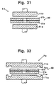
- the apparatus 60 for preparing an optical information recording disc comprises a pair of pressure disc plates 61a, 61b which have an effective pressure diameter smaller than the diameter of the substrate disc 81a, 81b of the information recording disc 80.
- the term of "effective pressure diameter" means a diameter of a round surface to be brought into contact with the surface of the substrate disc. In Fig. 31, the effective pressure diameter is equal to the diameter of the pressure disc plates 61a, 61b.
- the apparatus 70 comprises a pair of pressure disc plates 71a, 71b which also have an effective pressure diameter smaller than the diameter of the substrate disc 81a, 81b of the information recording disc 80.
- the diameter of the pressure disc plate 71a, 71b is larger than the diameter of the substrate disc 81a, 81b
- the surface to be brought into contact with the surface of the substrate disc is the area inside of the groove 72a, 72b, which is smaller than the diameter of the substrate disc 81a, 81b.
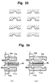
- Fig. 33 illustrates various exemplary sections of the groove which can be formed on the pressure plate.
- the groove can be formed on the pressure plate in the inner area, as is illustrated in Fig. 34.
- the groove 74a(74b) is formed in the inner area only, while the two grooves 71a(71b), 74a (74b) are formed in the vicinity of the peripheral end area and the inner area, respectively, in the embodiment (b).
- the groove in the inner area is effective to obviate undesired contact between the inner edge portion of the substrate disc (corresponding to the periphery of the center hole 86a(86b) of the substrate disc.
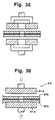
- Fig. 35 illustrates a preferred apparatus which has a pressure disc plate in the doughnut form.
- the pressure disc plate in the form of doughnut form has a diameter smaller than that of the substrate disc, while the diameter of the center hole of the pressure disc plate is larger than that of the center hole of the substrate.
- the apparatus 60 having pressure disc plates 61a, 61b with a relatively small effective diameter is favorably employed particularly when a substrate disc has a fin 87a(87b) at the outer peripheral edge.
- the pressure disc plate having a relatively small effective diameter the fins 87a, 87b do not disturb the formation of strong bonding between the substrate discs.
- the resulting information recording disc has an enough mechanical strength.
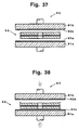
- the apparatus 90 comprises a pair of pressure disc plates 91a, 91b which has a surface layer 92a, 92b having a hardness less than the hardness of the substrate disc of the information recording disc 80.
- the surface layer 92a, 92b preferably has a hardness in the range of 10% to 80%, more preferably 40% to 80%, of the hardness of the substrate disc.
- the hardness is expressed in terms of Rockwell hardness.
- Examples of preferred materials of the surface layers include the following materials.
- the numeral given in the parentheses following the name of material represents a typical Rockwell hardness of the material.
- the Rockwell hardness of polycarbonate is 120.
- the examples of the preferred elastomers favorably employable for the formation of the surface layer having a relatively low hardness include the following:
- the above-mentioned elastomers have a hardness (defined in JIS-K-6301) in the range of 10% to 80%, particularly 30% to 80%.
- the polycarbonate has a hardness (JIS-K-6301) of 100.
- the surface layer having a relatively low hardness generally has a thickness of 0.5 to 10 mm, preferably 1 to 5 mm.
- the pressure disc plate having a surface of a relatively low hardness is favorably employed particularly when a substrate disc has a fin at the outer peripheral edge.
- the fins do not disturb the formation of strong bonding between the substrate discs.
- the resulting information recording disc has an enough mechanical strength.
- a polycarbonate substrate disc having a center hole and a tracking guide groove (diameter: 120 mm, thickness: 0.6 mm, inner diameter: 15 mm, width of groove: 0.4 ⁇ m, depth of groove: 200 nm) was rotated at a rate of 1,000 rpm, and the dye solution was coated on the rotating substrate disc by spin-coating. The coated dye layer was wiped off only in the inner peripheral area around the center hole, to produce an exposed ring area. The coated dye layer was then heated to 70°C for 10 minutes to give the recording layer having a thickness of 120 nm, having the form illustrated in Fig. 4.
- the recording layer was deposited Au by vacuum deposition to form a reflective layer having a thickness of 100 nm.
- the outer peripheral end of the Au-deposited layer was controlled to take a position slightly inside of the outer peripheral end of the recording layer.
- a UV curing resin solution available from Three Bond Co., Ltd., under product number 3070
- a UV curing resin solution available from Three Bond Co., Ltd., under product number 3070
- ultra-violet rays from a high pressure mercury lamp were irradiated onto the coated layer to cure the coated layer.
- the resulting resin layer i.e., protective layer
- a UV curing resin solution (available from Three Bond Co., Ltd., under product number 3070) was coated on the surface of the protective layer by spin coating at a rate of 1,500 rpm.
- a disc plate which was the same as the substrate disc and had an adhesive UV curing resin layer under the condition that the UV curing resin layers faced each other.
- the resulting composite body was placed in a combining apparatus between a pair of pressure disc plates (made of quartz glass) and the pressure disc plates were operated to give a pressure of 0.2 kg/cm 2 to the composite body. Then, ultra-violet rays from a high pressure mercury lamp were irradiated onto the pressure disc plate on the disc plate side to cure the UV curing resin layer.
- the resulting resin layer i.e., adhesive layer
- Example 1 The procedures of Example 1 were repeated except that the outer peripheral portion of the recording layer was not removed, to manufacture an optical information recording disc for comparison.
- Example 2 The procedures of Example 1 were repeated except for replacing the substrate disc with a substrate disc of the same size but having chamfered edge on the outer peripheral side (diameter: 120 mm, thickness: 0.6 mm, inner diameter: 15 mm, width of groove: 0.4 ⁇ m, depth of groove: 200 nm, dimensions of chamfered portion: 0.2 mm for depth direction, 0.5 mm for radial direction) and replacing the disc plate with a disc plate having the same size and the same chamfered edge, to manufacture an optical information recording disc of the invention in the form of Fig 12.
- Example 1 The procedures of Example 1 were repeated except for replacing the substrate disc with a substrate disc of the same size but having rough surface edge on the outer peripheral side (diameter: 120 mm, thickness: 0.6 mm, inner diameter: 15 mm, width of groove: 0.4 ⁇ m, depth of groove: 200 nm, surface roughness of the rough surface: 1 ⁇ m, which had been give by sand blast method) and replacing the disc plate with a disc plate having the same size and the same rough surface on the outer peripheral area, to manufacture an optical information recording disc of the invention.
- optical information recording discs obtained in the above-described examples were evaluated on their mechanical strength and storage stability by the following methods.
- the information recording disc was dropped ten times onto a concrete floor from the position of 1 m high, and the disc was checked whether there was observed separation at the outer edge portion or not under the following criteria:
- the information recording disc was stored for 240 hours under the conditions of 80°C and 85%RH, and the stored disc was observed at the edge portion. The appearance of the edge portion was evaluated in the same criteria as those of Drop impact test. The stored disc was further measured on its C/N on the outer peripheral area of groove in the same manner.
- Example 1 The procedures of Example 1 were repeated except for not providing the protective layer, to manufacture an optical information recording disc of the invention in the form of Fig 22.
- Example 1 The procedures of Example 1 were repeated except that the protective layer was not provided and that the outer peripheral portion of the recording layer was not removed, to manufacture an optical information recording disc for comparison.
- Example 2 The procedures of Example 1 were repeated except for not providing the protective layer, replacing the substrate disc with a substrate disc of the same size but having chamfered edge on the outer peripheral side (diameter: 120 mm, thickness: 0.6 mm, inner diameter: 15 mm, width of groove: 0.4 ⁇ m, depth of groove: 200 nm, dimensions of chamfered portion: 0.2 mm for depth direction, 0.5 mm for radial direction), and replacing the disc plate with a disc plate having the same size and the same chamfered edge, to manufacture an optical information recording disc of the invention in the form of Fig 29.
- Example 1 The procedures of Example 1 were repeated except for not providing the protective layer, replacing the substrate disc with a substrate disc of the same size but having rough surface edge on the outer peripheral side (diameter: 120 mm, thickness: 0.6 mm, inner diameter: 15 mm, width of groove: 0.4 ⁇ m, depth of groove: 200 nm, surface roughness of the rough surface: 1 ⁇ m, which had been give by sand blast method ), and replacing the disc plate with a disc plate having the same size and the same rough surface on the outer peripheral area, to manufacture an optical information recording disc of the invention.
- optical information recording discs obtained in the above-described examples were evaluated on their mechanical strength and storage stability by the methods described for the evaluation of the information recording discs of Examples 1-3 and Comparison Example 1.
Landscapes
- Engineering & Computer Science (AREA)
- Manufacturing & Machinery (AREA)
- Manufacturing Optical Record Carriers (AREA)
- Optical Recording Or Reproduction (AREA)
- Optical Record Carriers And Manufacture Thereof (AREA)
Applications Claiming Priority (18)
| Application Number | Priority Date | Filing Date | Title |
|---|---|---|---|
| JP27309996 | 1996-09-24 | ||
| JP273099/96 | 1996-09-24 | ||
| JP27309996A JP3665687B2 (ja) | 1996-09-24 | 1996-09-24 | 光情報記録媒体 |
| JP275580/96 | 1996-09-25 | ||
| JP27558096 | 1996-09-25 | ||
| JP8275580A JPH10106037A (ja) | 1996-09-25 | 1996-09-25 | 光情報記録媒体 |
| JP302420/96 | 1996-10-28 | ||
| JP30242196 | 1996-10-28 | ||
| JP8302421A JPH10134420A (ja) | 1996-10-28 | 1996-10-28 | 光情報記録媒体 |
| JP8302420A JPH10134419A (ja) | 1996-10-28 | 1996-10-28 | 光情報記録媒体 |
| JP30242096 | 1996-10-28 | ||
| JP302421/96 | 1996-10-28 | ||
| JP358553/96 | 1996-12-26 | ||
| JP35855396A JPH10199055A (ja) | 1996-12-26 | 1996-12-26 | 光情報記録媒体製造用圧着装置及び圧着方法 |
| JP35855396 | 1996-12-26 | ||
| JP39970/97 | 1997-02-07 | ||
| JP3997097 | 1997-02-07 | ||
| JP3997097A JPH10228679A (ja) | 1997-02-07 | 1997-02-07 | 光情報記録媒体製造用圧着装置及び圧着方法 |
Publications (3)
| Publication Number | Publication Date |
|---|---|
| EP0831473A2 true EP0831473A2 (de) | 1998-03-25 |
| EP0831473A3 EP0831473A3 (de) | 2000-01-05 |
| EP0831473B1 EP0831473B1 (de) | 2004-11-24 |
Family
ID=27549967
Family Applications (1)
| Application Number | Title | Priority Date | Filing Date |
|---|---|---|---|
| EP19970116651 Expired - Lifetime EP0831473B1 (de) | 1996-09-24 | 1997-09-24 | Optische Informationsaufzeichnungsplatte |
Country Status (4)
| Country | Link |
|---|---|
| US (2) | US5989669A (de) |
| EP (1) | EP0831473B1 (de) |
| CN (1) | CN1190785C (de) |
| DE (1) | DE69731705T2 (de) |
Cited By (5)
| Publication number | Priority date | Publication date | Assignee | Title |
|---|---|---|---|---|
| WO2003090220A1 (en) * | 2002-04-22 | 2003-10-30 | General Electric Company | Method for making limited play data storage media |
| US6861541B2 (en) | 2002-10-30 | 2005-03-01 | General Electric Company | Method for preparation of an anthraquinone colorant composition |
| US7087282B2 (en) | 2003-07-15 | 2006-08-08 | General Electric Company | Limited play optical storage medium, method for making the same |
| US7202292B2 (en) | 2003-07-15 | 2007-04-10 | General Electric Company | Colored polymeric resin composition with 1,8-diaminoanthraquinone derivative, article made therefrom, and method for making the same |
| EP1363280A4 (de) * | 2001-02-23 | 2007-05-30 | Tdk Corp | Herstellungsverfahren für ein optisches informationsmedium und optisches informationsmedium |
Families Citing this family (26)
| Publication number | Priority date | Publication date | Assignee | Title |
|---|---|---|---|---|
| US6319580B1 (en) * | 1998-06-16 | 2001-11-20 | Hitachi Maxell, Ltd. | Recording disk and producing method therefor |
| US6477011B1 (en) * | 1998-08-24 | 2002-11-05 | International Business Machines Corporation | Magnetic recording device having an improved slider |
| US6941572B2 (en) * | 2001-04-23 | 2005-09-06 | Matsushita Electric Industrial Co., Ltd. | Optical information recording medium and optical information recording/reproduction apparatus |
| KR100425949B1 (ko) * | 2001-08-27 | 2004-04-03 | 주식회사 비올디벨로퍼즈 | 광기록매체 |
| US20030148069A1 (en) * | 2002-02-07 | 2003-08-07 | Krebs Robert R. | Compound formable decorative laminate |
| US20050142369A1 (en) * | 2002-02-07 | 2005-06-30 | Canady Virgil B. | Compound formable decorative laminate door panel |
| US20050255331A1 (en) * | 2004-05-14 | 2005-11-17 | Krebs Robert R | Compound formable decorative laminate |
| US20050153336A1 (en) * | 2002-03-29 | 2005-07-14 | Bennett C. F. | Compositions and their uses directed to nucleic acid binding proteins |
| TWI317516B (en) * | 2002-06-07 | 2009-11-21 | Fujifilm Corp | Photo-data recording media |
| US7514037B2 (en) * | 2002-08-08 | 2009-04-07 | Kobe Steel, Ltd. | AG base alloy thin film and sputtering target for forming AG base alloy thin film |
| JP4417012B2 (ja) * | 2003-01-08 | 2010-02-17 | 三菱化学メディア株式会社 | 光情報記録媒体 |
| US8264929B2 (en) * | 2003-11-25 | 2012-09-11 | Dell Products L.P. | Optical medium recognition system and method with an optical drive having plural lasers |
| TWI325134B (en) * | 2004-04-21 | 2010-05-21 | Kobe Steel Ltd | Semi-reflective film and reflective film for optical information recording medium, optical information recording medium, and sputtering target |
| JP3907666B2 (ja) * | 2004-07-15 | 2007-04-18 | 株式会社神戸製鋼所 | レーザーマーキング用再生専用光情報記録媒体 |
| TW200639851A (en) * | 2005-02-18 | 2006-11-16 | Fuji Photo Film Co Ltd | Optical recording medium and method of manufacturing the same, substrate and method of using the same, and stamper and method of manufacturing the same |
| US7906194B2 (en) * | 2005-03-31 | 2011-03-15 | Cinram International Inc. | Optical disc with textured edge |
| JP2006294195A (ja) | 2005-04-14 | 2006-10-26 | Kobe Steel Ltd | 光情報記録用Ag合金反射膜、光情報記録媒体および光情報記録用Ag合金反射膜の形成用のAg合金スパッタリングターゲット |
| JP4527624B2 (ja) * | 2005-07-22 | 2010-08-18 | 株式会社神戸製鋼所 | Ag合金反射膜を有する光情報媒体 |
| JP4377861B2 (ja) * | 2005-07-22 | 2009-12-02 | 株式会社神戸製鋼所 | 光情報記録媒体用Ag合金反射膜、光情報記録媒体および光情報記録媒体用Ag合金反射膜の形成用のAg合金スパッタリングターゲット |
| JP2007035104A (ja) * | 2005-07-22 | 2007-02-08 | Kobe Steel Ltd | 光情報記録媒体用Ag合金反射膜、光情報記録媒体および光情報記録媒体用Ag合金反射膜の形成用のAg合金スパッタリングターゲット |
| JP2009032300A (ja) * | 2005-10-24 | 2009-02-12 | Panasonic Corp | 光情報記録媒体および光情報記録媒体の製造方法 |
| US20070269670A1 (en) * | 2006-05-17 | 2007-11-22 | Ronald Wilmer | Multilayered structures and their use as optical storage media |
| JP4173910B2 (ja) * | 2006-11-14 | 2008-10-29 | 松下電器産業株式会社 | 多層情報記録媒体及びその製造方法 |
| US8119216B2 (en) * | 2007-12-12 | 2012-02-21 | Taiyo Yuden Co., Ltd. | Optical information recording medium and manufacturing method thereof |
| CN102326200A (zh) * | 2008-12-31 | 2012-01-18 | 布莱阿姆青年大学 | 包含封装数据层的光学数据存储介质 |
| JP5376653B2 (ja) * | 2009-06-09 | 2013-12-25 | 株式会社フジクラ | フレキシブルプリント基板およびその製造方法 |
Family Cites Families (9)
| Publication number | Priority date | Publication date | Assignee | Title |
|---|---|---|---|---|
| US35947A (en) * | 1862-07-22 | Improvement in breech-loading fire-arms | ||
| US4539673A (en) * | 1983-07-26 | 1985-09-03 | Optical Disc Corporation | Optical disc air separation method and device |
| KR100264705B1 (ko) * | 1989-01-11 | 2000-09-01 | 야스카와 히데아키 | 광 디스크 및 이의 제조방법 |
| US5085910A (en) * | 1989-07-12 | 1992-02-04 | Hitachi Maxell, Ltd. | Optical data recording medium and method of manufacturing the same |
| US5213859A (en) * | 1990-12-21 | 1993-05-25 | Tdk Corporation | Optical recording disk |
| JPH04339332A (ja) * | 1991-05-16 | 1992-11-26 | Pioneer Electron Corp | 光記録ディスクおよびその製造方法 |
| JPH04353635A (ja) * | 1991-05-31 | 1992-12-08 | Mitsui Toatsu Chem Inc | 光記録媒体 |
| US5312663A (en) | 1991-12-27 | 1994-05-17 | Eastman Kodak Company | Optical element having durability enhancing layer |
| JPH087337A (ja) * | 1994-06-22 | 1996-01-12 | Pioneer Electron Corp | 光記録媒体 |
-
1997
- 1997-09-24 DE DE1997631705 patent/DE69731705T2/de not_active Expired - Lifetime
- 1997-09-24 CN CNB971214492A patent/CN1190785C/zh not_active Expired - Fee Related
- 1997-09-24 EP EP19970116651 patent/EP0831473B1/de not_active Expired - Lifetime
- 1997-09-24 US US08/937,010 patent/US5989669A/en not_active Expired - Lifetime
-
1999
- 1999-10-26 US US09/427,264 patent/US6238764B1/en not_active Expired - Fee Related
Cited By (5)
| Publication number | Priority date | Publication date | Assignee | Title |
|---|---|---|---|---|
| EP1363280A4 (de) * | 2001-02-23 | 2007-05-30 | Tdk Corp | Herstellungsverfahren für ein optisches informationsmedium und optisches informationsmedium |
| WO2003090220A1 (en) * | 2002-04-22 | 2003-10-30 | General Electric Company | Method for making limited play data storage media |
| US6861541B2 (en) | 2002-10-30 | 2005-03-01 | General Electric Company | Method for preparation of an anthraquinone colorant composition |
| US7087282B2 (en) | 2003-07-15 | 2006-08-08 | General Electric Company | Limited play optical storage medium, method for making the same |
| US7202292B2 (en) | 2003-07-15 | 2007-04-10 | General Electric Company | Colored polymeric resin composition with 1,8-diaminoanthraquinone derivative, article made therefrom, and method for making the same |
Also Published As
| Publication number | Publication date |
|---|---|
| EP0831473B1 (de) | 2004-11-24 |
| DE69731705D1 (de) | 2004-12-30 |
| US6238764B1 (en) | 2001-05-29 |
| CN1190785C (zh) | 2005-02-23 |
| US5989669A (en) | 1999-11-23 |
| CN1178981A (zh) | 1998-04-15 |
| DE69731705T2 (de) | 2005-04-07 |
| EP0831473A3 (de) | 2000-01-05 |
Similar Documents
| Publication | Publication Date | Title |
|---|---|---|
| EP0831473B1 (de) | Optische Informationsaufzeichnungsplatte | |
| US5424102A (en) | Optical recording medium and production thereof | |
| EP1094450B1 (de) | Optisches Aufzeichnungsmedium | |
| JPH043345A (ja) | 光情報記録媒体 | |
| EP1039449B1 (de) | Optisches Informationsaufzeichnungsmedium | |
| US20130216758A1 (en) | Optional disk and method for manufacturing the same | |
| US20050118417A1 (en) | Optical recording medium | |
| JP3039788B2 (ja) | 光ディスク用基板の製造方法および光ディスク | |
| JP3665687B2 (ja) | 光情報記録媒体 | |
| JP3718076B2 (ja) | 光情報記録媒体 | |
| US6984434B2 (en) | Recordable digital video disc | |
| JPH03120635A (ja) | 再生用情報記録媒体およびその製造方法 | |
| JPH10134419A (ja) | 光情報記録媒体 | |
| JP4088880B2 (ja) | 光ディスクの製造方法 | |
| JPH10134420A (ja) | 光情報記録媒体 | |
| JPH10106037A (ja) | 光情報記録媒体 | |
| EP0920920A2 (de) | Vorrichtung zur Schleuderbeschichtung zur Beschichtung von optischen Speicherplatten | |
| JPH0734496Y2 (ja) | 光情報記録媒体 | |
| JP3651709B2 (ja) | 光記録媒体及びその製造方法 | |
| JP2005267670A (ja) | 2層型光記録媒体及びその製造方法 | |
| JP2003228883A (ja) | 情報記録媒体、および情報記録媒体の製造方法 | |
| JPH05198004A (ja) | 光記録媒体及びその製造方法 | |
| JPH1125509A (ja) | 情報記録媒体 | |
| JPH10106034A (ja) | 光情報記録媒体 | |
| JP2002298442A (ja) | 貼り合わせ型光記録媒体およびその製造方法 |
Legal Events
| Date | Code | Title | Description |
|---|---|---|---|
| PUAI | Public reference made under article 153(3) epc to a published international application that has entered the european phase |
Free format text: ORIGINAL CODE: 0009012 |
|
| AK | Designated contracting states |
Kind code of ref document: A2 Designated state(s): DE FR GB |
|
| PUAL | Search report despatched |
Free format text: ORIGINAL CODE: 0009013 |
|
| AK | Designated contracting states |
Kind code of ref document: A3 Designated state(s): AT BE CH DE DK ES FI FR GB GR IE IT LI LU MC NL PT SE |
|
| 17P | Request for examination filed |
Effective date: 20000322 |
|
| AKX | Designation fees paid |
Free format text: DE FR GB |
|
| 17Q | First examination report despatched |
Effective date: 20030102 |
|
| GRAP | Despatch of communication of intention to grant a patent |
Free format text: ORIGINAL CODE: EPIDOSNIGR1 |
|
| GRAS | Grant fee paid |
Free format text: ORIGINAL CODE: EPIDOSNIGR3 |
|
| GRAA | (expected) grant |
Free format text: ORIGINAL CODE: 0009210 |
|
| AK | Designated contracting states |
Kind code of ref document: B1 Designated state(s): DE FR GB |
|
| REG | Reference to a national code |
Ref country code: GB Ref legal event code: FG4D |
|
| REF | Corresponds to: |
Ref document number: 69731705 Country of ref document: DE Date of ref document: 20041230 Kind code of ref document: P |
|
| PLBE | No opposition filed within time limit |
Free format text: ORIGINAL CODE: 0009261 |
|
| STAA | Information on the status of an ep patent application or granted ep patent |
Free format text: STATUS: NO OPPOSITION FILED WITHIN TIME LIMIT |
|
| ET | Fr: translation filed | ||
| 26N | No opposition filed |
Effective date: 20050825 |
|
| REG | Reference to a national code |
Ref country code: GB Ref legal event code: 732E |
|
| REG | Reference to a national code |
Ref country code: FR Ref legal event code: TP Ref country code: FR Ref legal event code: CD |
|
| PGFP | Annual fee paid to national office [announced via postgrant information from national office to epo] |
Ref country code: FR Payment date: 20110922 Year of fee payment: 15 Ref country code: DE Payment date: 20110831 Year of fee payment: 15 Ref country code: GB Payment date: 20110921 Year of fee payment: 15 |
|
| GBPC | Gb: european patent ceased through non-payment of renewal fee |
Effective date: 20120924 |
|
| REG | Reference to a national code |
Ref country code: FR Ref legal event code: ST Effective date: 20130531 |
|
| PG25 | Lapsed in a contracting state [announced via postgrant information from national office to epo] |
Ref country code: DE Free format text: LAPSE BECAUSE OF NON-PAYMENT OF DUE FEES Effective date: 20130403 Ref country code: GB Free format text: LAPSE BECAUSE OF NON-PAYMENT OF DUE FEES Effective date: 20120924 |
|
| PG25 | Lapsed in a contracting state [announced via postgrant information from national office to epo] |
Ref country code: FR Free format text: LAPSE BECAUSE OF NON-PAYMENT OF DUE FEES Effective date: 20121001 |
|
| REG | Reference to a national code |
Ref country code: DE Ref legal event code: R119 Ref document number: 69731705 Country of ref document: DE Effective date: 20130403 |