EP0831236A2 - Motorpumpe mit gekühltem Frequenzumformer - Google Patents
Motorpumpe mit gekühltem Frequenzumformer Download PDFInfo
- Publication number
- EP0831236A2 EP0831236A2 EP97116448A EP97116448A EP0831236A2 EP 0831236 A2 EP0831236 A2 EP 0831236A2 EP 97116448 A EP97116448 A EP 97116448A EP 97116448 A EP97116448 A EP 97116448A EP 0831236 A2 EP0831236 A2 EP 0831236A2
- Authority
- EP
- European Patent Office
- Prior art keywords
- motor
- pump
- plate
- pump according
- frequency converter
- Prior art date
- Legal status (The legal status is an assumption and is not a legal conclusion. Google has not performed a legal analysis and makes no representation as to the accuracy of the status listed.)
- Granted
Links
- 238000001816 cooling Methods 0.000 claims description 14
- 239000002826 coolant Substances 0.000 abstract 1
- 239000007788 liquid Substances 0.000 description 6
- 238000004804 winding Methods 0.000 description 2
- 238000010276 construction Methods 0.000 description 1
- 238000005192 partition Methods 0.000 description 1
Images


Classifications
-
- F—MECHANICAL ENGINEERING; LIGHTING; HEATING; WEAPONS; BLASTING
- F04—POSITIVE - DISPLACEMENT MACHINES FOR LIQUIDS; PUMPS FOR LIQUIDS OR ELASTIC FLUIDS
- F04D—NON-POSITIVE-DISPLACEMENT PUMPS
- F04D13/00—Pumping installations or systems
- F04D13/02—Units comprising pumps and their driving means
- F04D13/06—Units comprising pumps and their driving means the pump being electrically driven
- F04D13/0686—Mechanical details of the pump control unit
-
- F—MECHANICAL ENGINEERING; LIGHTING; HEATING; WEAPONS; BLASTING
- F04—POSITIVE - DISPLACEMENT MACHINES FOR LIQUIDS; PUMPS FOR LIQUIDS OR ELASTIC FLUIDS
- F04B—POSITIVE-DISPLACEMENT MACHINES FOR LIQUIDS; PUMPS
- F04B53/00—Component parts, details or accessories not provided for in, or of interest apart from, groups F04B1/00 - F04B23/00 or F04B39/00 - F04B47/00
- F04B53/08—Cooling; Heating; Preventing freezing
-
- F—MECHANICAL ENGINEERING; LIGHTING; HEATING; WEAPONS; BLASTING
- F04—POSITIVE - DISPLACEMENT MACHINES FOR LIQUIDS; PUMPS FOR LIQUIDS OR ELASTIC FLUIDS
- F04D—NON-POSITIVE-DISPLACEMENT PUMPS
- F04D1/00—Radial-flow pumps, e.g. centrifugal pumps; Helico-centrifugal pumps
- F04D1/06—Multi-stage pumps
-
- F—MECHANICAL ENGINEERING; LIGHTING; HEATING; WEAPONS; BLASTING
- F04—POSITIVE - DISPLACEMENT MACHINES FOR LIQUIDS; PUMPS FOR LIQUIDS OR ELASTIC FLUIDS
- F04D—NON-POSITIVE-DISPLACEMENT PUMPS
- F04D29/00—Details, component parts, or accessories
- F04D29/58—Cooling; Heating; Diminishing heat transfer
- F04D29/5813—Cooling the control unit
-
- F—MECHANICAL ENGINEERING; LIGHTING; HEATING; WEAPONS; BLASTING
- F04—POSITIVE - DISPLACEMENT MACHINES FOR LIQUIDS; PUMPS FOR LIQUIDS OR ELASTIC FLUIDS
- F04D—NON-POSITIVE-DISPLACEMENT PUMPS
- F04D29/00—Details, component parts, or accessories
- F04D29/58—Cooling; Heating; Diminishing heat transfer
- F04D29/586—Cooling; Heating; Diminishing heat transfer specially adapted for liquid pumps
- F04D29/588—Cooling; Heating; Diminishing heat transfer specially adapted for liquid pumps cooling or heating the machine
-
- F—MECHANICAL ENGINEERING; LIGHTING; HEATING; WEAPONS; BLASTING
- F04—POSITIVE - DISPLACEMENT MACHINES FOR LIQUIDS; PUMPS FOR LIQUIDS OR ELASTIC FLUIDS
- F04B—POSITIVE-DISPLACEMENT MACHINES FOR LIQUIDS; PUMPS
- F04B2203/00—Motor parameters
- F04B2203/02—Motor parameters of rotating electric motors
- F04B2203/0204—Frequency of the electric current
Definitions
- the invention relates to a motor pump with a cooled Frequency converter and an electric motor that a wet or Has dry running.
- the object of the invention is to provide a motor pump of the beginning to improve the type mentioned so that at simple Design and assembly optimal cooling of the Frequency converter is reached.
- the Frequency converter has a plate as a heat sink, on the at least one generating heat Electronic component is attached, the plate in particular perpendicular to the axis of rotation of the engine and from a branched part of the pumped medium can be cooled.
- Such a frequency converter can be on the front of the Motors simply attached as well as easily afterwards be replaced. This is a very good cooling the heat generated on the plate electronic components achieved.
- the Frequency converter can be installed anywhere.
- the plate has a Space limited by part of the medium is flowed through.
- the delivery medium for Plate through the inside of a can or Can of the engine flows. Furthermore, that should Pumped medium from the plate back to the pump suction side flow through a conduit that is in or on the outside of the motor and pump housing. This is it not required, as in the prior art known, a small part of the medium through the Interior of the motor shaft is returned to the pump, so that the pump shaft of simple construction and thus can be without an internal cavity.
- At least one adjustable throttle is arranged in the cooling circuit (Secondary circuit) of the pumped medium. This allows the for the electronics required cooling to each required size can be set.
- the pump Centrifugal or piston pump.
- the pump can also have several pump stages, each with an impeller.
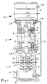
- the medium flows from an inlet 7 ( Figure 2) into one Pump suction chamber 8 and from there via the impellers 3 in a pump pressure chamber 9 and from there via a Outer jacket 10 to outlet 4, with inlet 7 and outlet 4th are arranged coaxially and transversely to the pump axis.
- the motor 5 has a coaxial can 11 in which the rotor 12 runs and that of the stator 13 Windings 14 is surrounded.
- the motor shaft 15 is in Bearings 16, 17 held and on the shaft 18 of the pump attached.
- the outer diameter D1 of the housing 21 is larger than that Outside diameter D2 of the motor and the outside diameter D3 of the pump.
- the frequency converter 20 is a plate near the motor 5 22 arranged perpendicular to the motor and pump axis 23, so that the axis 23 is perpendicular to the plate 22.
- the plate 22 is a heat sink for this Components.
- the plate 22 has at least one channel 24 which is flowed through by a part of the medium to the Cool plate 22.
- This channel 24 is located inside and / or to the side of the plate 22.
- the channel 24 part of a secondary cooling circuit, wherein the channel is connected to a line 25 which coaxial from the plate 24 to the center, the pump opposite end of the can 11 is guided.
- the end of the channel 24 is connected to a return line 26 connected outside the motor pumps along the Motor housing 6 and the pump housing 2 to the suction chamber 8 is returned.
- the liquid of the secondary cooling circuit is from the pressure chamber 9 through an opening 27 in the Partition 28 branches off between the pump and motor, wherein through the opening 27, the medium into the interior of the Can 11 is guided to cool the engine.
- the Pumped liquid flows through the containment can until to its end and from there through line 25 into the Channel 24 and then back through line 26 to Suction chamber 8.
- the channel 24 is over the plate 22 not by the shortest route, but by the Center of the plate 22 to the outer edge and there over a large edge area to the outlet 29 at which the line 26th connected.
- the channel 24 can also deviate from Figure 3 longer on the plate 22 in particular in Windings.
- the pump only one pump stage own or be a piston pump. Especially It is advantageous that the pump in both horizontal can also be operated in a vertical position. Further the connection point 30 on the frequency converter 20 cannot be arranged only laterally, but also on the front.
- the Electric motor no can or can have and thus be a dry runner.
- the space between plate 22 and the end of the can 11 from the liquid filled so that the liquid there the Plate 22 cools and channel 24 does not necessarily is required.
- secondary cooling circuit through the plate 22 and the Line 26 flows, an adjustable throttle arranged, so that the cooling circuit and thus the cooling of the plate 22nd is precisely controllable.
Landscapes
- Engineering & Computer Science (AREA)
- Mechanical Engineering (AREA)
- General Engineering & Computer Science (AREA)
- Physics & Mathematics (AREA)
- Thermal Sciences (AREA)
- Structures Of Non-Positive Displacement Pumps (AREA)
- Motor Or Generator Cooling System (AREA)
Abstract
Description
- Figur 1
- einen axialen Schnitt durch eine Motorkreiselpumpe,
- Figur 2
- eine Außenansicht der Motorkreiselpumpe und
- Figur 3
- einen Schnitt nach III-III in Figur 1.
Claims (12)
- Motorpumpe mit einem gekühlten Frequenzumformer (20) und einem Elektromotor (5), der einen Naß- oder Trockenläufer aufweist, dadurch gekennzeichnet, daß der Frequenzumformer als Wärmesenke eine Platte (22) aufweist, auf der mindestens ein Wärme erzeugendes Elektronikbauteil befestigt ist, wobei die Platte insbesondere senkrecht zur Motorendrehachse (23) liegt und von einem abgezweigten Teil des Fördermediums kühlbar ist.
- Motorpumpe nach Anspruch 1, dadurch gekennzeichnet, daß der Frequenzumformer (20) an der der Pumpe (1) abgewandten Stirnseite des Elektromotors insbesondere koaxial befestigt ist.
- Motorpumpe nach Anspruch 1 oder 2, dadurch gekennzeichnet, daß in und/oder an der Platte (22) ein Kanal (24) verläuft, der zur Kühlung der Platte vom Fördermedium durchflossen ist.
- Motorpumpe nach Anspruch 1 oder 2, dadurch gekennzeichnet, daß die Platte (22) einen Raum begrenzt, der von einem Teil des Fördermediums durchflossen ist.
- Motorpumpe nach einem der vorherigen Ansprüche, dadurch gekennzeichnet, daß das Fördermedium zur Platte (22) durch das Innere eines Spaltrohres oder Spalttopfes (11) des Motors (5) fließt.
- Motorpumpe nach einem der vorherigen Ansprüche, dadurch gekennzeichnet, daß das Fördermedium von der Platte (22) zurück zur Pumpensaugseite (8) durch eine Leitung (26) fließt, die in oder an der Außenseite des Motoren- und Pumpengehäuses liegt.
- Motorpumpe nach einem der vorherigen Ansprüche, dadurch gekennzeichnet, daß im Kühlkreislauf des Fördermediums mindestens eine regelbare Drossel angeordnet ist.
- Motorpumpe nach einem der vorherigen Ansprüche, dadurch gekennzeichnet, daß die Platte (22) mit dem Motorgehäuse (6) verbunden ist.
- Motorpumpe nach einem der vorherigen Ansprüche, dadurch gekennzeichnet, daß die Pumpe (1) eine Kreisel- oder Kolbenpumpe ist.
- Motorpumpe nach einem der vorherigen Ansprüche, dadurch gekennzeichnet, daß die Pumpe (1) mehrere Pumpstufen mit jeweils einem Laufrad (3) aufweist.
- Motorpumpe nach einem der vorherigen Ansprüche, dadurch gekennzeichnet, daß der Sekundärkreislauf (Bypaß) durch die von der Pumpe erzeugte Druckdifferenz "angetrieben" wird.
- Motorpumpe nach einem der vorherigen Ansprüche, dadurch gekennzeichnet, daß der Frequenzumformer an beliebiger Stelle (auch von der Pumpe entfernt) angebracht ist.
Applications Claiming Priority (2)
| Application Number | Priority Date | Filing Date | Title |
|---|---|---|---|
| DE19639098A DE19639098A1 (de) | 1996-09-24 | 1996-09-24 | Motorpumpe mit gekühltem Frequenzumformer |
| DE19639098 | 1996-09-24 |
Publications (4)
| Publication Number | Publication Date |
|---|---|
| EP0831236A2 true EP0831236A2 (de) | 1998-03-25 |
| EP0831236A3 EP0831236A3 (de) | 1999-04-28 |
| EP0831236B1 EP0831236B1 (de) | 2003-06-18 |
| EP0831236B2 EP0831236B2 (de) | 2007-08-15 |
Family
ID=7806672
Family Applications (1)
| Application Number | Title | Priority Date | Filing Date |
|---|---|---|---|
| EP97116448A Expired - Lifetime EP0831236B2 (de) | 1996-09-24 | 1997-09-22 | Motorpumpe mit gekühltem Frequenzumformer |
Country Status (2)
| Country | Link |
|---|---|
| EP (1) | EP0831236B2 (de) |
| DE (2) | DE19639098A1 (de) |
Cited By (11)
| Publication number | Priority date | Publication date | Assignee | Title |
|---|---|---|---|---|
| WO2000047464A1 (de) * | 1999-02-12 | 2000-08-17 | Siemens Aktiengesellschaft | Elektrischer schiffsantrieb |
| EP1132623A3 (de) * | 2000-03-06 | 2003-01-02 | Grundfos A/S | Motorbaueinheit für ein Tauchpumpenaggregat |
| WO2003064861A1 (en) * | 2002-01-25 | 2003-08-07 | Sundyne Corporation | Liquid cooled electric driven rotordynamic system |
| DE10214307A1 (de) * | 2002-03-28 | 2003-10-23 | Nash Elmo Ind Gmbh | Verdichtereinheit |
| EP1361368A3 (de) * | 2002-05-09 | 2004-07-28 | Dana Automotive Limited | Pumpenmotor mit Flüssigkeitskühlungssystem |
| WO2007071352A1 (de) * | 2005-12-20 | 2007-06-28 | Ksb Aktiengesellschaft | Drehzahlregelgerät in fluidgekühlter ausführung |
| ITTO20090317A1 (it) * | 2009-04-22 | 2010-10-23 | Ansaldo Ricerche S P A | Sistema di raffreddamento per motore elettrico ad alta densita' volumetrica di potenza, in particolare motore elettrico a flusso assiale |
| CN103649543A (zh) * | 2011-08-24 | 2014-03-19 | 株式会社日立产机系统 | 供水装置驱动用电力转换装置、供液装置驱动用电力转换装置 |
| EP3156663A1 (de) * | 2015-10-15 | 2017-04-19 | Grundfos Holding A/S | Kreiselpumpenaggregat |
| DE102016003169A1 (de) | 2016-03-16 | 2017-09-21 | Wilo Se | Kühleinrichtung für eine Pumpe mit Nassläufermotor |
| US10704565B2 (en) | 2014-06-24 | 2020-07-07 | Sterling Industry Consult Gmbh | Side-channel pump |
Families Citing this family (9)
| Publication number | Priority date | Publication date | Assignee | Title |
|---|---|---|---|---|
| JP4138111B2 (ja) * | 1998-06-18 | 2008-08-20 | アスモ株式会社 | 流体ポンプ装置 |
| DE10065796B4 (de) * | 2000-11-03 | 2020-12-24 | Wilo Se | Axial aufsteckbare Elektronik |
| DE102007036240A1 (de) * | 2007-08-02 | 2009-02-05 | Continental Automotive Gmbh | Flüssigkeitspumpe |
| DE102010005413B4 (de) | 2009-02-12 | 2023-03-30 | Hanon Systems Efp Deutschland Gmbh | Elektromotorisch angetriebene Pumpenanordnung |
| WO2013139628A1 (de) | 2012-03-19 | 2013-09-26 | Ixetic Bad Homburg Gmbh | Pumpenanordnung |
| DE102016105309A1 (de) * | 2016-03-22 | 2017-09-28 | Klaus Union Gmbh & Co. Kg | Magnetkupplungspumpe |
| JP2021032163A (ja) * | 2019-08-26 | 2021-03-01 | 株式会社荏原製作所 | ポンプ装置 |
| CN112234738B (zh) * | 2020-09-30 | 2021-08-27 | 台州谱罗顿机电有限公司 | 一种泵用变频电机 |
| DE102022131277A1 (de) | 2022-11-25 | 2024-05-29 | Schwäbische Hüttenwerke Automotive GmbH | Pumpe-Motor-Einheit mit integrierter Kühlung einer Elektronikkomponente |
Family Cites Families (15)
| Publication number | Priority date | Publication date | Assignee | Title |
|---|---|---|---|---|
| DE2715366B2 (de) * | 1977-04-06 | 1979-11-22 | Georg Dipl.-Ing. 8000 Muenchen Hienz | Elektrische Maschine mit einem Läufer, einem mit einer Mehrphasenwicklung versehenen Ständer und einer mit der Maschine baulich vereinten Kommutierungseinrichtung |
| DE3642726A1 (de) * | 1986-12-13 | 1988-06-23 | Grundfos Int | Drehzahlgeregeltes pumpenaggregat |
| DE3642729C3 (de) * | 1986-12-13 | 1997-05-07 | Grundfos Int | Pumpenaggregat zur Förderung von Flüssigkeiten oder Gasen |
| DE3642727A1 (de) * | 1986-12-13 | 1988-06-23 | Grundfos Int | Unterwasser-motorpumpe |
| DE3820005C1 (de) * | 1988-06-11 | 1989-10-05 | Grundfos International A/S, Bjerringbro, Dk | |
| US5038853A (en) * | 1989-01-17 | 1991-08-13 | Callaway Sr James K | Heat exchange assembly |
| DE4038663C2 (de) * | 1989-12-04 | 1996-02-29 | Mitsubishi Electric Corp | Wechselstrom-Lichtmaschine für Fahrzeuge |
| DE4106130A1 (de) * | 1991-02-27 | 1992-09-03 | Licentia Gmbh | Durch einen buerstenlosen gleichstrommotor angetriebenes geblaese mit einem spiralfoermigen gehaeuse |
| DE4231784A1 (de) * | 1991-06-22 | 1994-03-24 | Teves Gmbh Alfred | Elektromotorisch angetriebene Hydraulikpumpe |
| DE4121430C1 (de) * | 1991-06-28 | 1992-11-05 | Grundfos International A/S, Bjerringbro, Dk | |
| US5220809A (en) * | 1991-10-11 | 1993-06-22 | Nartron Corporation | Apparatus for cooling an air conditioning system electrical controller |
| DE4222394C1 (de) * | 1992-07-08 | 1993-12-09 | Grundfos A S Bjerringbro | Motorpumpe |
| JPH06280707A (ja) * | 1993-03-24 | 1994-10-04 | Aisan Ind Co Ltd | 電動式燃料ポンプ |
| DE59403962D1 (de) * | 1993-12-23 | 1997-10-09 | Abb Daimler Benz Transp | Kühlsystem für einen Motor |
| JP2829234B2 (ja) * | 1993-12-28 | 1998-11-25 | 三菱電機株式会社 | 車両用交流発電機 |
-
1996
- 1996-09-24 DE DE19639098A patent/DE19639098A1/de not_active Ceased
-
1997
- 1997-09-22 EP EP97116448A patent/EP0831236B2/de not_active Expired - Lifetime
- 1997-09-22 DE DE59710298T patent/DE59710298D1/de not_active Expired - Lifetime
Non-Patent Citations (1)
| Title |
|---|
| None |
Cited By (20)
| Publication number | Priority date | Publication date | Assignee | Title |
|---|---|---|---|---|
| WO2000047464A1 (de) * | 1999-02-12 | 2000-08-17 | Siemens Aktiengesellschaft | Elektrischer schiffsantrieb |
| EP1132623A3 (de) * | 2000-03-06 | 2003-01-02 | Grundfos A/S | Motorbaueinheit für ein Tauchpumpenaggregat |
| WO2003064861A1 (en) * | 2002-01-25 | 2003-08-07 | Sundyne Corporation | Liquid cooled electric driven rotordynamic system |
| US6685447B2 (en) | 2002-01-25 | 2004-02-03 | Hamilton Sundstrand | Liquid cooled integrated rotordynamic motor/generator station with sealed power electronic controls |
| CN100394039C (zh) * | 2002-01-25 | 2008-06-11 | 森德奈公司 | 通过液体冷却的电驱动转子动力系统 |
| DE10214307A1 (de) * | 2002-03-28 | 2003-10-23 | Nash Elmo Ind Gmbh | Verdichtereinheit |
| EP1361368A3 (de) * | 2002-05-09 | 2004-07-28 | Dana Automotive Limited | Pumpenmotor mit Flüssigkeitskühlungssystem |
| US6986648B2 (en) | 2002-05-09 | 2006-01-17 | Dana Automotive Limited | Electric pump |
| WO2007071352A1 (de) * | 2005-12-20 | 2007-06-28 | Ksb Aktiengesellschaft | Drehzahlregelgerät in fluidgekühlter ausführung |
| WO2010122404A1 (en) * | 2009-04-22 | 2010-10-28 | Ansaldo Energia S.P.A. | A cooling system for a high density power motor, in particular an axial-flux motor |
| ITTO20090317A1 (it) * | 2009-04-22 | 2010-10-23 | Ansaldo Ricerche S P A | Sistema di raffreddamento per motore elettrico ad alta densita' volumetrica di potenza, in particolare motore elettrico a flusso assiale |
| CN103649543A (zh) * | 2011-08-24 | 2014-03-19 | 株式会社日立产机系统 | 供水装置驱动用电力转换装置、供液装置驱动用电力转换装置 |
| US10704565B2 (en) | 2014-06-24 | 2020-07-07 | Sterling Industry Consult Gmbh | Side-channel pump |
| EP3161320B1 (de) * | 2014-06-24 | 2021-02-24 | Sterling Industry Consult GmbH | Seitenkanalpumpe |
| EP3156663A1 (de) * | 2015-10-15 | 2017-04-19 | Grundfos Holding A/S | Kreiselpumpenaggregat |
| CN107013469A (zh) * | 2015-10-15 | 2017-08-04 | 格兰富控股联合股份公司 | 离心泵机组 |
| US10400792B2 (en) | 2015-10-15 | 2019-09-03 | Grundfos Holding A/S | Centrifugal pump assembly comprising at least one impeller producing flow through and an annular space divided by at least two guide vanes into part-annular-spaces |
| CN107013469B (zh) * | 2015-10-15 | 2020-03-17 | 格兰富控股联合股份公司 | 离心泵机组 |
| DE102016003169A1 (de) | 2016-03-16 | 2017-09-21 | Wilo Se | Kühleinrichtung für eine Pumpe mit Nassläufermotor |
| DE102016003169B4 (de) * | 2016-03-16 | 2020-08-20 | Wilo Se | Kühleinrichtung für eine Pumpe mit Nassläufermotor |
Also Published As
| Publication number | Publication date |
|---|---|
| DE19639098A1 (de) | 1998-03-26 |
| EP0831236B1 (de) | 2003-06-18 |
| DE59710298D1 (de) | 2003-07-24 |
| EP0831236A3 (de) | 1999-04-28 |
| EP0831236B2 (de) | 2007-08-15 |
Similar Documents
| Publication | Publication Date | Title |
|---|---|---|
| EP0831236A2 (de) | Motorpumpe mit gekühltem Frequenzumformer | |
| EP0346730B1 (de) | Tauchpumpenaggregat | |
| EP1987579B1 (de) | Motorkreiselpumpe | |
| EP0987441B1 (de) | Rohrpumpe | |
| EP0906652B1 (de) | Elektromotor | |
| DE102014113412B3 (de) | Strömungsgekühlte Kühlmittelpumpe mit Nassläufer | |
| WO2021176309A1 (de) | Rotoranordnung mit flüssigkeitsgekühltem rotor | |
| EP2566015A1 (de) | Elektromotor | |
| DE3800336A1 (de) | Dichtungsfreie pumpe | |
| AT502566A1 (de) | Kühlmittelpumpe | |
| EP0629780A1 (de) | Tauchmotorpumpe | |
| EP4198309B1 (de) | Schraubenspindelpumpe | |
| DE102013018840B3 (de) | Elektromotorische Wasserpumpe | |
| EP4198261B1 (de) | Schraubenspindelpumpe | |
| EP1045149B1 (de) | Kühlmittelpumpe | |
| EP1538340A2 (de) | Kompakter Diagonallüfter | |
| WO2013037449A2 (de) | Elektromotorisches pumpenaggregat | |
| EP1447567B1 (de) | Vakuumpumpanordnung | |
| DE102004047637B4 (de) | Elektrisch betriebene Pumpe mit Außenrotor | |
| DE112021008181T5 (de) | Elektrische Kraftfahrzeug-Seitenkanal-Fluidpumpe | |
| DE102016009248A1 (de) | Elektrische Maschine und Maschine-Getriebe-Anordnung mit einer solchen elektrischen Maschine | |
| DE102004047635B4 (de) | Elektrisch betriebene Pumpe mit Innenrotor | |
| DE2044295A1 (de) | Stopfbuchsloses Pumpenaggregat | |
| DE19842169A1 (de) | Rohrpumpe | |
| EP3474423A1 (de) | Antriebseinrichtung für eine pumpe |
Legal Events
| Date | Code | Title | Description |
|---|---|---|---|
| PUAI | Public reference made under article 153(3) epc to a published international application that has entered the european phase |
Free format text: ORIGINAL CODE: 0009012 |
|
| AK | Designated contracting states |
Kind code of ref document: A2 Designated state(s): DE FR GB IT NL |
|
| AX | Request for extension of the european patent |
Free format text: AL;LT;LV;RO;SI |
|
| PUAL | Search report despatched |
Free format text: ORIGINAL CODE: 0009013 |
|
| AK | Designated contracting states |
Kind code of ref document: A3 Designated state(s): AT BE CH DE DK ES FI FR GB GR IE IT LI LU MC NL PT SE |
|
| AX | Request for extension of the european patent |
Free format text: AL;LT;LV;RO;SI |
|
| 17P | Request for examination filed |
Effective date: 19990325 |
|
| AKX | Designation fees paid |
Free format text: DE FR GB IT NL |
|
| 17Q | First examination report despatched |
Effective date: 20020517 |
|
| GRAH | Despatch of communication of intention to grant a patent |
Free format text: ORIGINAL CODE: EPIDOS IGRA |
|
| GRAH | Despatch of communication of intention to grant a patent |
Free format text: ORIGINAL CODE: EPIDOS IGRA |
|
| RAP1 | Party data changed (applicant data changed or rights of an application transferred) |
Owner name: WILO AG |
|
| GRAA | (expected) grant |
Free format text: ORIGINAL CODE: 0009210 |
|
| AK | Designated contracting states |
Designated state(s): DE FR GB IT NL |
|
| REG | Reference to a national code |
Ref country code: GB Ref legal event code: FG4D Free format text: NOT ENGLISH |
|
| REF | Corresponds to: |
Ref document number: 59710298 Country of ref document: DE Date of ref document: 20030724 Kind code of ref document: P |
|
| GBT | Gb: translation of ep patent filed (gb section 77(6)(a)/1977) |
Effective date: 20031009 |
|
| ET | Fr: translation filed | ||
| PLBI | Opposition filed |
Free format text: ORIGINAL CODE: 0009260 |
|
| PLBQ | Unpublished change to opponent data |
Free format text: ORIGINAL CODE: EPIDOS OPPO |
|
| PLAX | Notice of opposition and request to file observation + time limit sent |
Free format text: ORIGINAL CODE: EPIDOSNOBS2 |
|
| 26 | Opposition filed |
Opponent name: GRUNDFOS A/S Effective date: 20040309 |
|
| NLR1 | Nl: opposition has been filed with the epo |
Opponent name: GRUNDFOS A/S |
|
| PLBB | Reply of patent proprietor to notice(s) of opposition received |
Free format text: ORIGINAL CODE: EPIDOSNOBS3 |
|
| PUAH | Patent maintained in amended form |
Free format text: ORIGINAL CODE: 0009272 |
|
| STAA | Information on the status of an ep patent application or granted ep patent |
Free format text: STATUS: PATENT MAINTAINED AS AMENDED |
|
| 27A | Patent maintained in amended form |
Effective date: 20070815 |
|
| AK | Designated contracting states |
Kind code of ref document: B2 Designated state(s): DE FR GB IT NL |
|
| NLR2 | Nl: decision of opposition |
Effective date: 20070815 |
|
| GBTA | Gb: translation of amended ep patent filed (gb section 77(6)(b)/1977) | ||
| NLR3 | Nl: receipt of modified translations in the netherlands language after an opposition procedure | ||
| ET3 | Fr: translation filed ** decision concerning opposition | ||
| PGFP | Annual fee paid to national office [announced via postgrant information from national office to epo] |
Ref country code: NL Payment date: 20140910 Year of fee payment: 18 |
|
| PGFP | Annual fee paid to national office [announced via postgrant information from national office to epo] |
Ref country code: GB Payment date: 20140917 Year of fee payment: 18 |
|
| REG | Reference to a national code |
Ref country code: FR Ref legal event code: PLFP Year of fee payment: 19 |
|
| PGFP | Annual fee paid to national office [announced via postgrant information from national office to epo] |
Ref country code: DE Payment date: 20150916 Year of fee payment: 19 |
|
| PGFP | Annual fee paid to national office [announced via postgrant information from national office to epo] |
Ref country code: FR Payment date: 20150825 Year of fee payment: 19 |
|
| PGFP | Annual fee paid to national office [announced via postgrant information from national office to epo] |
Ref country code: IT Payment date: 20150925 Year of fee payment: 19 |
|
| GBPC | Gb: european patent ceased through non-payment of renewal fee |
Effective date: 20150922 |
|
| REG | Reference to a national code |
Ref country code: NL Ref legal event code: MM Effective date: 20151001 |
|
| PG25 | Lapsed in a contracting state [announced via postgrant information from national office to epo] |
Ref country code: GB Free format text: LAPSE BECAUSE OF NON-PAYMENT OF DUE FEES Effective date: 20150922 |
|
| PG25 | Lapsed in a contracting state [announced via postgrant information from national office to epo] |
Ref country code: NL Free format text: LAPSE BECAUSE OF NON-PAYMENT OF DUE FEES Effective date: 20151001 |
|
| REG | Reference to a national code |
Ref country code: DE Ref legal event code: R119 Ref document number: 59710298 Country of ref document: DE |
|
| REG | Reference to a national code |
Ref country code: FR Ref legal event code: ST Effective date: 20170531 |
|
| PG25 | Lapsed in a contracting state [announced via postgrant information from national office to epo] |
Ref country code: FR Free format text: LAPSE BECAUSE OF NON-PAYMENT OF DUE FEES Effective date: 20160930 Ref country code: DE Free format text: LAPSE BECAUSE OF NON-PAYMENT OF DUE FEES Effective date: 20170401 |
|
| PG25 | Lapsed in a contracting state [announced via postgrant information from national office to epo] |
Ref country code: IT Free format text: LAPSE BECAUSE OF NON-PAYMENT OF DUE FEES Effective date: 20160922 |