EP0825460B1 - Lenticular lens sheet, display front plate and transmission type projection screen - Google Patents
Lenticular lens sheet, display front plate and transmission type projection screen Download PDFInfo
- Publication number
- EP0825460B1 EP0825460B1 EP97114087A EP97114087A EP0825460B1 EP 0825460 B1 EP0825460 B1 EP 0825460B1 EP 97114087 A EP97114087 A EP 97114087A EP 97114087 A EP97114087 A EP 97114087A EP 0825460 B1 EP0825460 B1 EP 0825460B1
- Authority
- EP
- European Patent Office
- Prior art keywords
- layer
- lenticular lens
- lens sheet
- colored
- light
- Prior art date
- Legal status (The legal status is an assumption and is not a legal conclusion. Google has not performed a legal analysis and makes no representation as to the accuracy of the status listed.)
- Expired - Lifetime
Links
Images


Classifications
-
- G—PHYSICS
- G03—PHOTOGRAPHY; CINEMATOGRAPHY; ANALOGOUS TECHNIQUES USING WAVES OTHER THAN OPTICAL WAVES; ELECTROGRAPHY; HOLOGRAPHY
- G03B—APPARATUS OR ARRANGEMENTS FOR TAKING PHOTOGRAPHS OR FOR PROJECTING OR VIEWING THEM; APPARATUS OR ARRANGEMENTS EMPLOYING ANALOGOUS TECHNIQUES USING WAVES OTHER THAN OPTICAL WAVES; ACCESSORIES THEREFOR
- G03B21/00—Projectors or projection-type viewers; Accessories therefor
- G03B21/54—Accessories
- G03B21/56—Projection screens
-
- G—PHYSICS
- G02—OPTICS
- G02B—OPTICAL ELEMENTS, SYSTEMS OR APPARATUS
- G02B3/00—Simple or compound lenses
- G02B3/0006—Arrays
- G02B3/0012—Arrays characterised by the manufacturing method
- G02B3/0031—Replication or moulding, e.g. hot embossing, UV-casting, injection moulding
-
- G—PHYSICS
- G03—PHOTOGRAPHY; CINEMATOGRAPHY; ANALOGOUS TECHNIQUES USING WAVES OTHER THAN OPTICAL WAVES; ELECTROGRAPHY; HOLOGRAPHY
- G03B—APPARATUS OR ARRANGEMENTS FOR TAKING PHOTOGRAPHS OR FOR PROJECTING OR VIEWING THEM; APPARATUS OR ARRANGEMENTS EMPLOYING ANALOGOUS TECHNIQUES USING WAVES OTHER THAN OPTICAL WAVES; ACCESSORIES THEREFOR
- G03B21/00—Projectors or projection-type viewers; Accessories therefor
- G03B21/54—Accessories
- G03B21/56—Projection screens
- G03B21/60—Projection screens characterised by the nature of the surface
- G03B21/62—Translucent screens
- G03B21/625—Lenticular translucent screens
-
- G—PHYSICS
- G02—OPTICS
- G02B—OPTICAL ELEMENTS, SYSTEMS OR APPARATUS
- G02B3/00—Simple or compound lenses
- G02B3/0006—Arrays
- G02B3/0037—Arrays characterized by the distribution or form of lenses
- G02B3/005—Arrays characterized by the distribution or form of lenses arranged along a single direction only, e.g. lenticular sheets
-
- G—PHYSICS
- G02—OPTICS
- G02B—OPTICAL ELEMENTS, SYSTEMS OR APPARATUS
- G02B3/00—Simple or compound lenses
- G02B3/0006—Arrays
- G02B3/0037—Arrays characterized by the distribution or form of lenses
- G02B3/0056—Arrays characterized by the distribution or form of lenses arranged along two different directions in a plane, e.g. honeycomb arrangement of lenses
-
- G—PHYSICS
- G02—OPTICS
- G02F—OPTICAL DEVICES OR ARRANGEMENTS FOR THE CONTROL OF LIGHT BY MODIFICATION OF THE OPTICAL PROPERTIES OF THE MEDIA OF THE ELEMENTS INVOLVED THEREIN; NON-LINEAR OPTICS; FREQUENCY-CHANGING OF LIGHT; OPTICAL LOGIC ELEMENTS; OPTICAL ANALOGUE/DIGITAL CONVERTERS
- G02F1/00—Devices or arrangements for the control of the intensity, colour, phase, polarisation or direction of light arriving from an independent light source, e.g. switching, gating or modulating; Non-linear optics
- G02F1/01—Devices or arrangements for the control of the intensity, colour, phase, polarisation or direction of light arriving from an independent light source, e.g. switching, gating or modulating; Non-linear optics for the control of the intensity, phase, polarisation or colour
- G02F1/13—Devices or arrangements for the control of the intensity, colour, phase, polarisation or direction of light arriving from an independent light source, e.g. switching, gating or modulating; Non-linear optics for the control of the intensity, phase, polarisation or colour based on liquid crystals, e.g. single liquid crystal display cells
- G02F1/133—Constructional arrangements; Operation of liquid crystal cells; Circuit arrangements
- G02F1/1333—Constructional arrangements; Manufacturing methods
- G02F1/1335—Structural association of cells with optical devices, e.g. polarisers or reflectors
- G02F1/133526—Lenses, e.g. microlenses or Fresnel lenses
Definitions
- the present invention relates to a lenticular lens sheet, a display front plate and a transmission type projection screen, all of which are suitable for projecting and observing an image supplied from an image source having a cell structure, such as a liquid crystal device (LCD), a digital micro-mirror device (DMD) or the like.
- a cell structure such as a liquid crystal device (LCD), a digital micro-mirror device (DMD) or the like.
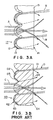
- Fig. 4 shows an example of the conventional transmission type projection screen.
- this transmission type projection screen comprises a lenticular lens sheet 40.
- the lenticular lens sheet 40 is provided, on a light incident face side 41 thereof, with a converging lens section 42, such as a lenticular lens.
- the lenticular lens sheet 40 On a light emitting face 44 in the vicinity of a focus of the lens section 42, the lenticular lens sheet 40 includes a plurality of non-light emitting sections 47 covered with light absorbing layer 48 which will be referred to black stripes (BS), hereinafter.
- BS black stripes
- a conventional art projection television has been developed with the above-mentioned LCD or DMD. Also in this projection television (TV), the above BS lenticular lens sheet has been employed for purposes of an improvement of diffusion performance and a prevention of the external light from reflection.
- a pitch of the lenticular lens is preferably decreased so as to be 1/3.5 (equal to ten thirty fifth) or less of a pitch of lattice pattern projected.
- the projection TV having the LCD or DMD often produces a glaring picture which is called "scintillation".
- sintillation a glaring picture which is called "scintillation"
- to decrease the pitch of the lenticular lens would be effective in order to weaken the above-mentioned scintillation.
- the transmission type projection screen having the BS lenticular lens sheet as shown in Fig. 4 operates to diffuse the light in a wide range of an angle of 40 degrees or more.
- a distance between the incident lens and the light emitting face has to be established to be one point three times as large as a pitch of the incident lens.
- the transmission type projection screen as the projection TV using the LCD or the DMD utilizes a lenticular lens sheet, which is provided only on a light emitting face side with colored lenticular lenses (light emitting side lenticular lens sheet), a lenticular lens sheet which is provided only on a light incident face side with colored lenticular lenses (light incident side lenticular lens sheet) or the like.
- some are shaped to have partially circular or partially elliptical cross sections, and others are shaped so as to utilize total reflection.
- the later lenses have a common problem of impossibility of an exact die transferal by the extruding process due to their singular configurations, so that they have no choice but to be produced by the casting process having a poor productivity.
- Fig. 6 shows a relationship between an inclination angle at a light incident position of the light incident-side lenticular lens and the emission angle of the light.
- a letter ⁇ designates a foot angle at the foot portion of the incident lens
- a letter ⁇ an emission angle of the light entering into the foot portion of the lens
- a letter h a height of the incident lens
- l a distance between an incident point (i.e. the foot portion of the lens) and a converging point, respectively.
- Table 4 shows the emission angle and respective positions of the converging points relative to the lens angle at the foot portion of the lens.
- a letter n denotes a refractive index and p a pitch of the lens.
- the distance (h + l) in case of 60 degrees of the lens angle at the foot portion of the lens ⁇ is set to 1.41, while the distance (h + l) in case of 70 degrees of the lens angle ⁇ is set to 1.25.
- the distance between the incident lens portion and the light emitting face must be established to be about 1.3 times as large as the lens pitch. This means that a reduction of a pitch of the lens makes a thickness of the lens thinner, thereby causing the rigidity of lens to be weakened and the forming of lens to be complicated.
- EP 0 371 432 A2 discloses a transmission type screen having a screen body constituted by at least one plastic sheet formed of a multiplicity of transparent plastic strands arranged in that shape of a sheet, each of the strands being welded together at outer surfaces thereof.
- Each of the transparent strands may have a main portion and another portion different from the main portion in terms of optical effects.
- a lenticular lens sheet having the features disclosed in claim 1, a display front plate having the features disclosed in claim 14 and a transmission type projection screen having the features disclosed in claim 17.
- Preferred embodiments are defined in the dependent subclaims.
- a lenticular lens sheet, a display front plate and a transmission type projection screen which are capable of preventing the reflection of outside light for the improvement of contrast of image without decreasing the intensity of image light excessively and by which the fine-pitching of the image can be realized.
- the object of the present invention described above can be accomplished by a lenticular lens sheet as defined in claim 1.
- the colored layer has a configuration along a shape of the lens portion.
- the colored layer has a thickness from 0.05 to 1.0 times as large as a pitch of the lenticular lens configuration.
- a thickness of the colored layer is established so as to meet an inequality represented by: t 1 > t 2 wherein
- At least the colored layer contains additive diffusion agents.
- the lenticular lens sheet of the invention further comprises a diffusion layer which is formed between the colored layer and the substrate layer and into which diffusion agents are mixed and it is preferable that the colored layer does not contain the diffusion agents and the substrate layer is either non-colored or colored paler than the colored layer.
- the lenticular lens configuration includes a portion a tangential line of which exhibits an angle more than a critical angle with respect to a surface of the lenticular lens sheet.
- the substrate layer has a light emitting face consisting of a flat surface or a mat surface.
- a thickness of the lenticular lens sheet is more than 1.5 mm.
- the substrate layer is provided, on a light emitting face thereof, with at least one of an anti-reflection layer, a low reflecting layer, a polarization filtering layer, an anti-static layer, an anti-glare treatment layer and a hard coated treatment layer.
- the light emitting face consists of a mat surface.
- the substrate layer is provided, on a light emitting face thereof, with at least one of an anti-reflection layer, a low reflecting layer, a polarization filtering layer, an antistatic layer, an anti-glare treatment layer and a hard coated treatment layer.
- the present transmission type projection screen further comprises a display front plate as defined in claim 14 and arranged on a viewer's side of the lenticular lens sheet, wherein the substrate layer has a light emitting face consisting of a flat surface or a mat surface.
- the substrate layer is provided, on a light emitting face thereof, with at least one of an anti-reflection layer, a low reflecting layer, a polarization filtering layer, an anti-static layer, an anti-glare treatment layer and a hard coated treatment layer.
- the transmission type projection screen has a transmissivity of total light beams from 40 to 70 per cent.
- Figs. 1A and 1B show a lenticular lens sheet and a transmission type projection screen in accordance with an embodiment of the present invention.
- Fig. 2 is an explanatory diagram of the path of outside light reflected by the lenticular lens sheet.
- the transmission type projection screen 1 comprises a lenticular lens sheet 10 and a Fresnel lens sheet 20 and constitutes a rear projection television system together with a light source 2 of a single-lens type of LCD projector.
- the lenticular lens sheet 10 is provided, on a light incident face 11 thereof, with a lens portion 12 in the form of a convex lenticular lens.
- the lens portion 12 has an achromatic or chromatic colored layer 13 formed in the vicinity of the incident face 11.
- the lenticular lens sheet 10 further includes a substrate layer 15 extending from the colored layer 13 up to the light emitting face 14.
- This colored layer 13 has a function to enhance a contrast of the image in spite of the lenticular lens sheet (10) only having the lenticular lenses on one side (the incident face) thereof.
- Fig. 3B is an explanatory diagram of the function of the conventional art lenticular lens sheet 60 of "colored-body" type
- Fig. 3A is an explanatory diagram of the function of the colored layer 13 of the present lenticular lens sheet 10.
- the conventional lenticular lens sheet 60 of Fig. 3B which has one incident face on one side, is a sheet of the "colored-body" type including a darkened or colored substrate layer 65.
- external light D1 entering from an observer's side is totally reflected by a lens portion 62 provided on an incident face 61, so that external light D4 emits to the viewer's side again.
- the light D1 repeats its reflections along a "lenticular lens" profile of the lens portion 62 (D1 ⁇ D2 ⁇ D3 ⁇ D4).
- an optical path length of the external light B running in the colored layer 13 becomes to be 5 to 10 times as long as the optical path length of the image light A in the same layer 13.
- the former length is at the most 2 to 3 times as long as the later length.
- the lenticular lens sheet 10 of the invention is capable of restricting the reflection of the outside light B without reducing the intensity of the image light A so much, it is possible to provide a screen exhibiting fine contrast.
- the lenticular lens sheet 10 of the embodiment absorbs the total reflecting external light B by the lens portion 12 of the light incident face 11 effectively. Accordingly, the lens portion 12 must be provided with a part which is inclined so that its lens angle at the foot portion of the lens ⁇ (Fig. 5) relative to the screen face is more than at least the critical angle (approx. 45 degrees). While, if all the lens portion of the lenticular lens sheet is inclined with the angle ⁇ less than the critical angle, such a lens sheet would not hold a dominant position to the colored-body type of lenticular lens sheet 60 of Fig. 3B.
- Fig. 5 is an explanatory diagram for exhibiting a fact that the incident angle ⁇ ' of the external light, which has entered into the lenticular lens perpendicularly, in case of projecting from the light incident lens portion or totally reflecting therefrom is equal to the lens angle ⁇ of the emitting or incident point relative to a screen face.
- the incident lens portion contains a part of which lens angle ⁇ is more than the critical angle sin -1 (1/n). (n : refractive index of lenticular lens sheet)
- the lenticular lens configuration of the lens portion 12 normally has a portion formed at an angle more than 60 degrees so that the diffusion angle becomes to be more than 40 degrees.
- the coloring (or darkening) for the achromatic or chromatic colored layer 12 may be carried out by mixing or dispersing dyes and fine pigments into the mold resin of the lenticular lens sheet 10.
- Achromatic-color such as black, gray etc., or chromatic color which absorbs or permeates a light in specific color for controlling the balance of three primary colors (red, green, blue) in spectral characteristics of the light source is applicable to the color for the colored layer.
- the coloring density of the colored layer 13 is established to be higher than that of a portion (i.e. the substrate layer 15) on the light emitting face's side of the layer 13, while the coloring density of the substrate layer 15 is maintained to be either zero or a lowered value.
- Fig. 7 shows a relationship between the transmissivity of the transmission type projection screen of the embodiment and the contrast.
- the coloring density is in a range of 40 to 70%. That is, if the coloring density is reduced so that the transmissivity becomes higher than 70 %, the intensity of the external light, which returns the observer's side after total-reflecting on the lens portion 12, will be increased thereby to influence the contrast badly in spite of the improved transmissivity. Conversely, if the coloring density is increased in a manner that the transmissivity becomes to be less than 40 %, the reflection of the external light on the light emitting face 14 will come into prominence together with the deteriorated transmissivity of the image light, so that the contrast will get worse, too.
- a variety of the present light incident side lenticular lens sheets having various coloring densities for the colored layers were firstly manufactured. Subsequently, the transmissivity and reflectivity of these samples were measured by using a spectrophotometer (UV 2100 made by Shimazu Seisakusho Co. Ltd.). The obtained transmissivity, the reflectivity and the calculated ratios therebetween (i.e. values of transmissivity/reflectivity) were plotted in the figure, respectively.
- a vertical axis on the left hand denotes a level of the reflectivity
- another vertical axis on the right hand denotes a level of the ratio of transmissivity to reflectivity.
- the lenticular lens sheet of the invention does not absorb the external light reflected on the light emitting face on the observer's side, even when increasing the coloring density thereby to reduce the transmissivity, the ratio of the transmissivity to the reflectivity gradually increases to reach its peak at 50 % in transmissivity. This is the reason it would be better to color the colored layer so that the transmissivity is included in the range of 40 to 70 %.
- a thickness t 1 of the colored layer 13 is 0.05 to 1.0 times as large as the pitch of the lenticular lens 12. Again, it is also desirable that the thickness t 1 of the colored layer 13 is less than a half of the sheet thickness t 0 . These preferable conditions are derived from a purpose of forming the colored layer 13 in a position where the reflected external light is apt to pass.
- Fig. 8 is an explanatory diagram of an optimum value of the thickness of the colored layer of the lenticular lens sheet in accordance with the embodiment.
- the lenticular lens sheet 10 of the embodiment makes use of the external light's running along the lens portion 12, it is desirable that the colored layer 13 has a profile along the lens portion 12.
- the thickness t 1 of the colored layer 13 will be about one-tenth of a pitch of the lenticular lens configuration.
- the thickness of the colored layer 13 is less than either the pitch of the lenticular lens configuration or at least a half of the sheet thickness.
- Fig. 9 shows the thickness of the colored layer of the lenticular lens sheet of the invention.
- the colored layer 13 is formed in a manner that the thickness t 1 at the top of the lens portion 12 exceeds the thickness t 2 at the foot of the portion 12. (t 1 > t 2 )
- the colored layer 13 is formed with an uniform thickness, a light path ( in the colored layer 13) of the image light incoming through a foot 12b of the lens portion 12 would be larger than that of the image light incoming through a top 12a, the more the image light would be absorbed in the colored layer 13. As a result, the intensity of light projecting within a range of 30 to 40 degrees would be decreased accordingly.
- Fig. 10 is a characteristic diagram of light diffusion, showing a comparison between a case of making a thickness of the foot of the colored layer thin and another case to make the thickness of the colored layer uniform.
- the thickness of the colored layer 13 is established corresponding to a path length of the incident light, it will be possible to realize the light diffusive characteristics in accordance with the design of lens advantageously.
- the lenticular lens sheet 10 can contain light diffusion agents added to at least the colored layer 13.
- the light diffusion agents are added to 100 weight parts of resinous material forming the lenticular lens sheet 10 by 8 weight parts thereby to apply a preferable vertical diffusion on the light projected from the light source 2.
- the light diffusion agents may be applied all over the lenticular lens sheet 10. However, if the light diffusion agents are on the viewer's side of the colored layer 13, the external light will be diffused there to return toward the viewer before a part of the external light reaches the colored layer 13. From this point of view, it is preferable to make the diffusion agents in the substrate layer 15 thin. In other words, providing that a weight concentration of the light diffusion agents mixed into the colored layer 13 is represented by C 1 while a weight concentration of the light diffusion agents mixed into the substrate layer 15 is represented by C 0 , it is desirable to establish a relationship expressed by the following inequality: 0 ⁇ C 0 ⁇ C 1
- the light emitting face 14 is shaped to be flat. In such a case, it would be better not to mix the diffusion agents into the substrate layer 15 in order to facilitate the formation of lamination.
- the diffusion layers 16, 16C may be formed intermediately without mixing the diffusion agents into the colored layer 13, while the low-density colored layers 15B may be arranged on the viewer's side in order to absorb the light component reflected by the diffusion agents.
- the lenticular lens sheet 10 has the light emitting face 14 consisting of a flat face or a mat face. In case of the flat face, it is possible to enhance the clearness of image. Further, since the colored layer 13 is formed in the vicinity of the light incident face 11, the desirable picture can be provided because of no reflection on the light incident face 11 in comparison with the arrangement where a transparent flat panel is disposed on the whole face of the screen.
- the light emitting face 14 is formed to be a flat face, it is possible to dispose the anti-reflection layer, the low-reflection layer, the polarization filtering layer or the like. Then, it is possible to realize the contrast similar to that of the conventional lenticular lens with a light-absorption layer.
- the projecting face 14 may be provided with the hard-coated layer, the anti-glare layer, the antistatic layer etc.
- the lenticular lens sheet of the embodiment can be provided with a variety of functional layers. Therefore, when adopting a plate thickness more than 1.5 mm for ensuring the rigidity, it is possible to abolish the front plate which has been used in the screen having the conventional BS lenticular lens sheet.
- the lenticular lens sheet 10 of the embodiment is not provided, on the light emitting face 14, with an optical-axis correcting lens, it is desirable to use the light source 2 in combination with a single-lens or single-tube type of projector which projects the image light by a single lens.
- a LCD projector which firstly divides light of a lamp into three primary color components by a dichroic mirror, secondly allows them to transmit through the LCD while giving the image information and finally composes these light components for projection, may be used for the light source 2.
- the lenticular lens sheet of the embodiment may be produced by a first step of juxtaposing a roll die for forming the light incident face, which has a profile contrary to the lenticular lens sheet to be manufactured, and another roll die for forming the light emitting face, which has a flat or mat surface, a second step of extruding-colored resinous material on the light incident-face side of a space between both roll dies while extruding transparent or colored resinous material, which is thinner than the colored layer and which may contain the light diffusion agents, and a third step of molding them for the sheet.
- the lenticular lens sheet may be produced by extruding the resinous material between the above dies for molding, while simultaneously introducing a colored film so as to follow the roll die for forming the incident face and subsequently laminating the film on the molded resin.
- a lens layer may be formed on a film substrate by using colored ultraviolet hardened resin.
- Figs. 11A to 11C show other embodiments of the lenticular lens sheet of the invention.
- the shown lenticular lens sheet 10A is provided with the colored layer 13 of which configuration does not follow a profile of the lens. In this way, even if a boundary surface between the colored layer 13 and the substrate layer 15 is flat, it is possible to provide the fine lenticular lens sheet in comparison with the colored-body type of lenticular lens sheet, as estimated from a comparison between Fig. 3A and Fig. 3B. Note, in order to allow the colored layer 13 to play an effect close to the lens portion 12, it is preferable that a thickness of the colored layer 13 is less than either a pitch of the lenticular lens or at least one a half of the sheet thickness.
- the lenticular lens sheet 10B of Fig. 11B comprises the colored layer 13 formed along the lens portion 12, a substrate layer 15B colored lightly without any diffusion agents, and an intermediate layer (diffusion layer) 16 with the diffusion agents between the colored layer 13 and the substrate layer 15B.
- the lenticular lens sheet 10C of Fig. 11C comprises the colored layer 13 formed along the lens portion 12, the substrate layer 15B colored lightly without the diffusion agents and disposed on the side of the light emitting face 14, another substrate layer 15C non-colored with no diffusion agents and an intermediate layer (diffusion layer) 16C with the diffusion agents between the colored layer 13 and the substrate layer 15C.
- these lenticular lens sheets 10B, 10C it is possible to absorb the reflected light effectively due to the diffusion agents and the light colored layer.
- Fig. 12 shows the transmission type projection screen in accordance with another embodiment of the present invention.
- the lenticular lens sheet 10 of the embodiment is associated with a Fresnel lens sheet 20 (or a film Fresnel lens sheet) having a Fresnel lens formed on the light emitting side (viewer side), thereby constituting a transmission type projection screen 1A.
- a display front plate 30 is arranged on the viewer's side of the lenticular lens sheet 10.
- the display front plate 30 is provided, on a face of the light incident side of a substrate layer 35, with a colored lenticular lens 32 for vertical diffusion.
- a colored lenticular lens 32 for vertical diffusion.
- the display front plate 30 may be provided, on a light emitting face 34 of the substrate layer 35, with a variety of functional layers, such as an anti-reflection layer, a low reflective layer, a polarization filtering layer, an antistatic layer, an anti-glare layer, a hard coated layer and so on.
- functional layers such as an anti-reflection layer, a low reflective layer, a polarization filtering layer, an antistatic layer, an anti-glare layer, a hard coated layer and so on.
- the lenticular lens sheet 10 was made of impact resistance acrylic resin (a refractive index: 1.51), having the lens portion 12 (a pitch P of 0.2 mm; a transverse diameter a of 0.12 mm; a longitudinal diameter b of 0.15 mm), a sheet thickness t 0 of 1.0 mm and a thickness t 1 of the colored layer 13 of 0.06 mm.
- the single-faced lenticular lens sheet has a configuration identical to that of the lenticular lens sheet 10 of Embodiment 1 and exhibits a screen gain substantially equal to that of Embodiment 1.
- the lenticular lens sheets of Embodiment 1 and Comparative example 1 were assembled in the rear projection TV using a LCD light source for comparative observation: the lenticular lens sheets of Embodiment 1 on the right-hand side of the TV; the lenticular lens sheets of Comparative example 1 on the left-hand side of the TV.
- the screen of Embodiment 1 exhibits a fine contrast.
- a spectrophotometer UV 2100 made by Shimazu Seisakusho Co. Ltd.
- Embodiment 1 is twice or more as large as that of Comparative example 1, while the ratio of Embodiment 2 is similar to that of BS lenticular lens sheet, as shown with Table 1 below.
- transmissivity [%] reflectivity[%] transmissivity/reflectivity Embodiment 1 63.0 11.7 5.4 Embo. 2(AR) 63.3 8.4 7.5
- the lenticular lens sheet 10 was made of the impact resistance acrylic resin, having the lens portion 12 (a pitch P of 0.4 mm; a transverse diameter a of 0.12 mm; a longitudinal diameter b of 0.28 mm), a sheet thickness t 0 of 1.0 mm and a thickness t 1 of the colored layer 13 of 0.06 mm (the ideal thickness of the colored layer: 0.056 mm). Then, the transmissivity and reflectivity of this lenticular lens sheet were measured by the spectrophotometer. The result exhibited the transmissivity of 65 %, the reflectivity of 7.2 % and the ratio of transmissivity to reflectivity of 9.0.
- the lenticular lens sheet having the identical configuration but the thickness t 1 of the colored layer of 0.10 mm was prepared and the transmissivity and reflectivity were also measured by the spectrophotometer.
- the result exhibited the transmissivity of 62 %, the reflectivity of 8.0 % and the ratio of transmissivity to reflectivity of 7.8.
- the lenticular lens sheet 10 was made of the impact resistance acrylic resin (a refractive index: 1.51), having the lens portion 12 (a pitch P of 0.14 mm; a transverse diameter a of 0.07 mm; a longitudinal diameter b of 0.09 mm), a sheet thickness t 0 of 0.9 mm and a thickness t 1 of the colored layer 13 of 0.04 mm.
- the lenticular lens sheets (different thickness) of claim 1 were produced by a double-layered extruding method (co-extruding method) of methacrylic material. Next, each of the resulting lenticular lens sheets was abutted against a Fresnel lens sheet of 2 mm in thickness and respective four sides of both sheets were fixed with each other by means of tapes for setting-up.
- the lenticular lens sheet having a thickness more than 1.5 mm makes it difficult for a viewer to confirm the distortion in reflected image, providing a fine outward appearance. Further, under a comparison with the front plates of the identical thickness, it is found that both sheets of the identical thickness exhibit the same estimation results.
- the present invention it is possible to prevent the external light from reflecting without decreasing the intensity of image light so much, so that the contrast of image on the screen can be enhanced. Furthermore, it is possible to progress the fine pitching of image.
Landscapes
- Physics & Mathematics (AREA)
- General Physics & Mathematics (AREA)
- Engineering & Computer Science (AREA)
- Manufacturing & Machinery (AREA)
- Optics & Photonics (AREA)
- Overhead Projectors And Projection Screens (AREA)
- Optical Elements Other Than Lenses (AREA)
Applications Claiming Priority (6)
| Application Number | Priority Date | Filing Date | Title |
|---|---|---|---|
| JP216250/96 | 1996-08-16 | ||
| JP21625096 | 1996-08-16 | ||
| JP21625096 | 1996-08-16 | ||
| JP9170568A JP2939207B2 (ja) | 1996-08-16 | 1997-06-26 | レンチキュラーレンズシート、ディスプレイ用前面板及び透過型スクリーン |
| JP170568/97 | 1997-06-26 | ||
| JP17056897 | 1997-06-26 |
Publications (3)
| Publication Number | Publication Date |
|---|---|
| EP0825460A2 EP0825460A2 (en) | 1998-02-25 |
| EP0825460A3 EP0825460A3 (en) | 1998-08-12 |
| EP0825460B1 true EP0825460B1 (en) | 2002-11-06 |
Family
ID=26493524
Family Applications (1)
| Application Number | Title | Priority Date | Filing Date |
|---|---|---|---|
| EP97114087A Expired - Lifetime EP0825460B1 (en) | 1996-08-16 | 1997-08-14 | Lenticular lens sheet, display front plate and transmission type projection screen |
Country Status (8)
| Country | Link |
|---|---|
| EP (1) | EP0825460B1 (ko) |
| JP (1) | JP2939207B2 (ko) |
| KR (1) | KR100258057B1 (ko) |
| CN (1) | CN1100271C (ko) |
| DE (1) | DE69716836T2 (ko) |
| DK (1) | DK0825460T3 (ko) |
| SG (1) | SG73467A1 (ko) |
| TW (1) | TW372282B (ko) |
Families Citing this family (15)
| Publication number | Priority date | Publication date | Assignee | Title |
|---|---|---|---|---|
| JPH11125704A (ja) * | 1997-10-22 | 1999-05-11 | Dainippon Printing Co Ltd | レンチキュラーレンズシート及びその製造方法 |
| US6421181B1 (en) * | 1998-08-03 | 2002-07-16 | Dai Nippon Printing Co., Ltd. | Lenticular lens sheet and rear projection screen |
| JP4131891B2 (ja) * | 1999-09-03 | 2008-08-13 | ローム株式会社 | レンズアレイ、およびレンズアレイの製造方法 |
| CN1294317A (zh) | 1999-11-01 | 2001-05-09 | 孙柏林 | 正投屏幕 |
| JP3770006B2 (ja) | 1999-11-01 | 2006-04-26 | 松下電器産業株式会社 | 背面投写型画像表示装置 |
| JP2004145251A (ja) * | 2002-08-30 | 2004-05-20 | Seiko Epson Corp | 透過型スクリーン及びリア型プロジェクタ |
| KR100553887B1 (ko) * | 2003-06-24 | 2006-02-24 | 삼성전자주식회사 | 수직 및 수평으로 광시야각을 갖는 영상표시용 스크린 및이를 구비하는 프로젝션 텔레비전 |
| JP4386249B2 (ja) | 2003-07-01 | 2009-12-16 | 三菱電機株式会社 | 背面投写スクリーン用拡散構造板及び背面投写スクリーン |
| KR100744839B1 (ko) * | 2004-10-05 | 2007-08-01 | 엘지마이크론 주식회사 | 디스플레이용 스크린의 마이크로렌즈배열시트 |
| JP4650131B2 (ja) * | 2005-07-07 | 2011-03-16 | セイコーエプソン株式会社 | レンズ基板およびリア型プロジェクタ |
| JP5170273B2 (ja) * | 2011-03-22 | 2013-03-27 | 大日本印刷株式会社 | 面光源装置と透過型表示装置 |
| KR20140097125A (ko) * | 2011-11-29 | 2014-08-06 | 미쯔비시 레이온 가부시끼가이샤 | 광학 필름, 면발광체 및 광학 필름의 제조 방법 |
| JP6028829B1 (ja) * | 2015-04-09 | 2016-11-24 | 大日本印刷株式会社 | 反射型スクリーン、映像表示システム |
| CN111552130A (zh) * | 2020-06-17 | 2020-08-18 | 苏州绘格光电科技有限公司 | 调光膜及其制备方法 |
| CN115113416B (zh) * | 2022-07-22 | 2023-08-25 | 吉林省钜鸿智能技术有限公司 | 一种户外裸眼3d显示屏 |
Family Cites Families (8)
| Publication number | Priority date | Publication date | Assignee | Title |
|---|---|---|---|---|
| JPH0233231Y2 (ko) * | 1979-11-08 | 1990-09-07 | ||
| EP0371432B1 (en) * | 1988-11-28 | 1995-07-05 | Mitsubishi Rayon Co., Ltd. | Transmission type screen and method of manufacturing the same |
| JPH032852A (ja) * | 1989-05-31 | 1991-01-09 | Pioneer Electron Corp | レンチキュラー型蛍光体スクリーン |
| JPH03230101A (ja) * | 1990-02-05 | 1991-10-14 | Matsushita Electron Corp | カラー固体撮像装置およびその製造方法 |
| DE4005933A1 (de) * | 1990-02-26 | 1991-08-29 | Bke Bildtechnisches Konstrukti | Rueckprojektions-scheibe |
| US5400114A (en) * | 1991-09-05 | 1995-03-21 | Hitachi, Ltd. | Rear-projection screen and a rear projection image display employing the rear-projection screen |
| JPH0572634A (ja) * | 1991-09-12 | 1993-03-26 | Seiko Epson Corp | 背面投射スクリーン |
| DE29601195U1 (de) * | 1996-01-26 | 1996-04-11 | P & I Gmbh | Rückprojektionsmaterial |
-
1997
- 1997-06-26 JP JP9170568A patent/JP2939207B2/ja not_active Expired - Fee Related
- 1997-08-13 SG SG1997002932A patent/SG73467A1/en unknown
- 1997-08-13 TW TW086111616A patent/TW372282B/zh not_active IP Right Cessation
- 1997-08-14 KR KR1019970038980A patent/KR100258057B1/ko not_active IP Right Cessation
- 1997-08-14 DK DK97114087T patent/DK0825460T3/da active
- 1997-08-14 EP EP97114087A patent/EP0825460B1/en not_active Expired - Lifetime
- 1997-08-14 DE DE69716836T patent/DE69716836T2/de not_active Expired - Fee Related
- 1997-08-16 CN CN97120513A patent/CN1100271C/zh not_active Expired - Lifetime
Also Published As
| Publication number | Publication date |
|---|---|
| DE69716836T2 (de) | 2003-08-28 |
| JP2939207B2 (ja) | 1999-08-25 |
| JPH10111537A (ja) | 1998-04-28 |
| DK0825460T3 (da) | 2003-03-10 |
| TW372282B (en) | 1999-10-21 |
| CN1181509A (zh) | 1998-05-13 |
| SG73467A1 (en) | 2000-06-20 |
| DE69716836D1 (de) | 2002-12-12 |
| EP0825460A3 (en) | 1998-08-12 |
| KR19980018702A (ko) | 1998-06-05 |
| CN1100271C (zh) | 2003-01-29 |
| EP0825460A2 (en) | 1998-02-25 |
| KR100258057B1 (ko) | 2000-06-01 |
Similar Documents
| Publication | Publication Date | Title |
|---|---|---|
| US5880887A (en) | Lenticular lens sheet, display front plate and transmission type projection screen | |
| EP0825460B1 (en) | Lenticular lens sheet, display front plate and transmission type projection screen | |
| US6785048B2 (en) | Rear-projection screen and rear-projection image display | |
| KR0140051B1 (ko) | 투과형스크린 및그 제조방법 | |
| JP3070586B2 (ja) | 透過型スクリーン、レンチキュラーシート及びそれを用いた背面投写型画像ディスプレイ装置 | |
| US7190517B2 (en) | Light diffusing substrate, transmission screen, and display device | |
| US6185038B1 (en) | Rear projection screen with light diffusion sheet and projector using same | |
| US6762883B2 (en) | Lenticular lens sheet and rear projection screen | |
| EP0911654B1 (en) | Lenticular lens sheet and process for producing the same | |
| JPH07248537A (ja) | 透過型スクリーンとその製造方法 | |
| JPS6332527A (ja) | 透過型投影スクリ−ン用レンズシ−ト | |
| US6961176B2 (en) | Fresnel lens sheet, rear projection screen and rear projection display | |
| JPH06160982A (ja) | 透過型スクリーン | |
| JP3508908B2 (ja) | 透過型スクリーン及びレンチキュラーレンズシート | |
| JP2000112036A (ja) | レンチキュラ―レンズシ―ト及び透過型スクリ―ン | |
| JP2003287819A (ja) | 背面投射型スクリーンおよび背面投射型ディスプレイ | |
| KR100213601B1 (ko) | 투과형스크린 및 그 제조방법 | |
| JP3335588B2 (ja) | 透過型スクリーン | |
| JPH05289176A (ja) | 透過型スクリーン | |
| JPH04270334A (ja) | 透過型投影スクリーン | |
| JPH04355442A (ja) | 透過形スクリーン | |
| JPH10148888A (ja) | 透過型スクリーン | |
| JP2001004808A (ja) | レンチキュラーレンズシート及び透過型スクリーン |
Legal Events
| Date | Code | Title | Description |
|---|---|---|---|
| PUAI | Public reference made under article 153(3) epc to a published international application that has entered the european phase |
Free format text: ORIGINAL CODE: 0009012 |
|
| AK | Designated contracting states |
Kind code of ref document: A2 Designated state(s): BE DE DK FR NL |
|
| PUAL | Search report despatched |
Free format text: ORIGINAL CODE: 0009013 |
|
| AK | Designated contracting states |
Kind code of ref document: A3 Designated state(s): AT BE CH DE DK ES FI FR GB GR IE IT LI LU MC NL PT SE |
|
| 17P | Request for examination filed |
Effective date: 19990114 |
|
| AKX | Designation fees paid |
Free format text: BE DE DK FR NL |
|
| RBV | Designated contracting states (corrected) |
Designated state(s): BE DE DK FR NL |
|
| 17Q | First examination report despatched |
Effective date: 20001213 |
|
| GRAG | Despatch of communication of intention to grant |
Free format text: ORIGINAL CODE: EPIDOS AGRA |
|
| GRAG | Despatch of communication of intention to grant |
Free format text: ORIGINAL CODE: EPIDOS AGRA |
|
| GRAH | Despatch of communication of intention to grant a patent |
Free format text: ORIGINAL CODE: EPIDOS IGRA |
|
| GRAH | Despatch of communication of intention to grant a patent |
Free format text: ORIGINAL CODE: EPIDOS IGRA |
|
| GRAA | (expected) grant |
Free format text: ORIGINAL CODE: 0009210 |
|
| AK | Designated contracting states |
Kind code of ref document: B1 Designated state(s): BE DE DK FR NL |
|
| REF | Corresponds to: |
Ref document number: 69716836 Country of ref document: DE Date of ref document: 20021212 |
|
| REG | Reference to a national code |
Ref country code: DK Ref legal event code: T3 |
|
| ET | Fr: translation filed | ||
| PLBE | No opposition filed within time limit |
Free format text: ORIGINAL CODE: 0009261 |
|
| STAA | Information on the status of an ep patent application or granted ep patent |
Free format text: STATUS: NO OPPOSITION FILED WITHIN TIME LIMIT |
|
| 26N | No opposition filed |
Effective date: 20030807 |
|
| PGFP | Annual fee paid to national office [announced via postgrant information from national office to epo] |
Ref country code: BE Payment date: 20050627 Year of fee payment: 9 |
|
| PG25 | Lapsed in a contracting state [announced via postgrant information from national office to epo] |
Ref country code: BE Free format text: LAPSE BECAUSE OF NON-PAYMENT OF DUE FEES Effective date: 20060831 |
|
| BERE | Be: lapsed |
Owner name: *DAI NIPPON PRINTING CO. LTD Effective date: 20060831 |
|
| PGFP | Annual fee paid to national office [announced via postgrant information from national office to epo] |
Ref country code: NL Payment date: 20080729 Year of fee payment: 12 Ref country code: DE Payment date: 20080908 Year of fee payment: 12 |
|
| PGFP | Annual fee paid to national office [announced via postgrant information from national office to epo] |
Ref country code: FR Payment date: 20080723 Year of fee payment: 12 |
|
| REG | Reference to a national code |
Ref country code: NL Ref legal event code: V1 Effective date: 20100301 |
|
| REG | Reference to a national code |
Ref country code: FR Ref legal event code: ST Effective date: 20100430 |
|
| PG25 | Lapsed in a contracting state [announced via postgrant information from national office to epo] |
Ref country code: NL Free format text: LAPSE BECAUSE OF NON-PAYMENT OF DUE FEES Effective date: 20100301 Ref country code: FR Free format text: LAPSE BECAUSE OF NON-PAYMENT OF DUE FEES Effective date: 20090831 Ref country code: DE Free format text: LAPSE BECAUSE OF NON-PAYMENT OF DUE FEES Effective date: 20100302 |
|
| PGFP | Annual fee paid to national office [announced via postgrant information from national office to epo] |
Ref country code: DK Payment date: 20160819 Year of fee payment: 20 |
|
| REG | Reference to a national code |
Ref country code: DK Ref legal event code: EUP Effective date: 20170814 |