EP0825102A2 - Drehmoment-Begrenzungseinrichtung für Motoren in elektrisch angetriebenen Fahrzeugen - Google Patents
Drehmoment-Begrenzungseinrichtung für Motoren in elektrisch angetriebenen Fahrzeugen Download PDFInfo
- Publication number
- EP0825102A2 EP0825102A2 EP97306340A EP97306340A EP0825102A2 EP 0825102 A2 EP0825102 A2 EP 0825102A2 EP 97306340 A EP97306340 A EP 97306340A EP 97306340 A EP97306340 A EP 97306340A EP 0825102 A2 EP0825102 A2 EP 0825102A2
- Authority
- EP
- European Patent Office
- Prior art keywords
- motor
- torque
- driving power
- electric driving
- limiting device
- Prior art date
- Legal status (The legal status is an assumption and is not a legal conclusion. Google has not performed a legal analysis and makes no representation as to the accuracy of the status listed.)
- Withdrawn
Links
- 230000000875 corresponding effect Effects 0.000 description 6
- 230000001276 controlling effect Effects 0.000 description 5
- 230000005540 biological transmission Effects 0.000 description 4
- 238000010276 construction Methods 0.000 description 4
- 238000001514 detection method Methods 0.000 description 2
- 238000010586 diagram Methods 0.000 description 2
- 238000003079 width control Methods 0.000 description 2
- 230000002596 correlated effect Effects 0.000 description 1
- 230000000694 effects Effects 0.000 description 1
- 238000000034 method Methods 0.000 description 1
- 230000001105 regulatory effect Effects 0.000 description 1
- 239000000758 substrate Substances 0.000 description 1
Images


Classifications
-
- B—PERFORMING OPERATIONS; TRANSPORTING
- B62—LAND VEHICLES FOR TRAVELLING OTHERWISE THAN ON RAILS
- B62M—RIDER PROPULSION OF WHEELED VEHICLES OR SLEDGES; POWERED PROPULSION OF SLEDGES OR SINGLE-TRACK CYCLES; TRANSMISSIONS SPECIALLY ADAPTED FOR SUCH VEHICLES
- B62M6/00—Rider propulsion of wheeled vehicles with additional source of power, e.g. combustion engine or electric motor
- B62M6/40—Rider propelled cycles with auxiliary electric motor
- B62M6/45—Control or actuating devices therefor
-
- H—ELECTRICITY
- H02—GENERATION; CONVERSION OR DISTRIBUTION OF ELECTRIC POWER
- H02P—CONTROL OR REGULATION OF ELECTRIC MOTORS, ELECTRIC GENERATORS OR DYNAMO-ELECTRIC CONVERTERS; CONTROLLING TRANSFORMERS, REACTORS OR CHOKE COILS
- H02P7/00—Arrangements for regulating or controlling the speed or torque of electric DC motors
- H02P7/06—Arrangements for regulating or controlling the speed or torque of electric DC motors for regulating or controlling an individual DC dynamo-electric motor by varying field or armature current
-
- B—PERFORMING OPERATIONS; TRANSPORTING
- B60—VEHICLES IN GENERAL
- B60L—PROPULSION OF ELECTRICALLY-PROPELLED VEHICLES; SUPPLYING ELECTRIC POWER FOR AUXILIARY EQUIPMENT OF ELECTRICALLY-PROPELLED VEHICLES; ELECTRODYNAMIC BRAKE SYSTEMS FOR VEHICLES IN GENERAL; MAGNETIC SUSPENSION OR LEVITATION FOR VEHICLES; MONITORING OPERATING VARIABLES OF ELECTRICALLY-PROPELLED VEHICLES; ELECTRIC SAFETY DEVICES FOR ELECTRICALLY-PROPELLED VEHICLES
- B60L50/00—Electric propulsion with power supplied within the vehicle
- B60L50/50—Electric propulsion with power supplied within the vehicle using propulsion power supplied by batteries or fuel cells
- B60L50/53—Electric propulsion with power supplied within the vehicle using propulsion power supplied by batteries or fuel cells in combination with an external power supply, e.g. from overhead contact lines
-
- B—PERFORMING OPERATIONS; TRANSPORTING
- B62—LAND VEHICLES FOR TRAVELLING OTHERWISE THAN ON RAILS
- B62M—RIDER PROPULSION OF WHEELED VEHICLES OR SLEDGES; POWERED PROPULSION OF SLEDGES OR SINGLE-TRACK CYCLES; TRANSMISSIONS SPECIALLY ADAPTED FOR SUCH VEHICLES
- B62M6/00—Rider propulsion of wheeled vehicles with additional source of power, e.g. combustion engine or electric motor
- B62M6/40—Rider propelled cycles with auxiliary electric motor
- B62M6/45—Control or actuating devices therefor
- B62M6/50—Control or actuating devices therefor characterised by detectors or sensors, or arrangement thereof
-
- B—PERFORMING OPERATIONS; TRANSPORTING
- B62—LAND VEHICLES FOR TRAVELLING OTHERWISE THAN ON RAILS
- B62M—RIDER PROPULSION OF WHEELED VEHICLES OR SLEDGES; POWERED PROPULSION OF SLEDGES OR SINGLE-TRACK CYCLES; TRANSMISSIONS SPECIALLY ADAPTED FOR SUCH VEHICLES
- B62M6/00—Rider propulsion of wheeled vehicles with additional source of power, e.g. combustion engine or electric motor
- B62M6/40—Rider propelled cycles with auxiliary electric motor
- B62M6/60—Rider propelled cycles with auxiliary electric motor power-driven at axle parts
-
- B—PERFORMING OPERATIONS; TRANSPORTING
- B60—VEHICLES IN GENERAL
- B60L—PROPULSION OF ELECTRICALLY-PROPELLED VEHICLES; SUPPLYING ELECTRIC POWER FOR AUXILIARY EQUIPMENT OF ELECTRICALLY-PROPELLED VEHICLES; ELECTRODYNAMIC BRAKE SYSTEMS FOR VEHICLES IN GENERAL; MAGNETIC SUSPENSION OR LEVITATION FOR VEHICLES; MONITORING OPERATING VARIABLES OF ELECTRICALLY-PROPELLED VEHICLES; ELECTRIC SAFETY DEVICES FOR ELECTRICALLY-PROPELLED VEHICLES
- B60L2200/00—Type of vehicles
- B60L2200/12—Bikes
-
- Y—GENERAL TAGGING OF NEW TECHNOLOGICAL DEVELOPMENTS; GENERAL TAGGING OF CROSS-SECTIONAL TECHNOLOGIES SPANNING OVER SEVERAL SECTIONS OF THE IPC; TECHNICAL SUBJECTS COVERED BY FORMER USPC CROSS-REFERENCE ART COLLECTIONS [XRACs] AND DIGESTS
- Y02—TECHNOLOGIES OR APPLICATIONS FOR MITIGATION OR ADAPTATION AGAINST CLIMATE CHANGE
- Y02T—CLIMATE CHANGE MITIGATION TECHNOLOGIES RELATED TO TRANSPORTATION
- Y02T10/00—Road transport of goods or passengers
- Y02T10/60—Other road transportation technologies with climate change mitigation effect
- Y02T10/64—Electric machine technologies in electromobility
-
- Y—GENERAL TAGGING OF NEW TECHNOLOGICAL DEVELOPMENTS; GENERAL TAGGING OF CROSS-SECTIONAL TECHNOLOGIES SPANNING OVER SEVERAL SECTIONS OF THE IPC; TECHNICAL SUBJECTS COVERED BY FORMER USPC CROSS-REFERENCE ART COLLECTIONS [XRACs] AND DIGESTS
- Y02—TECHNOLOGIES OR APPLICATIONS FOR MITIGATION OR ADAPTATION AGAINST CLIMATE CHANGE
- Y02T—CLIMATE CHANGE MITIGATION TECHNOLOGIES RELATED TO TRANSPORTATION
- Y02T10/00—Road transport of goods or passengers
- Y02T10/60—Other road transportation technologies with climate change mitigation effect
- Y02T10/70—Energy storage systems for electromobility, e.g. batteries
-
- Y—GENERAL TAGGING OF NEW TECHNOLOGICAL DEVELOPMENTS; GENERAL TAGGING OF CROSS-SECTIONAL TECHNOLOGIES SPANNING OVER SEVERAL SECTIONS OF THE IPC; TECHNICAL SUBJECTS COVERED BY FORMER USPC CROSS-REFERENCE ART COLLECTIONS [XRACs] AND DIGESTS
- Y02—TECHNOLOGIES OR APPLICATIONS FOR MITIGATION OR ADAPTATION AGAINST CLIMATE CHANGE
- Y02T—CLIMATE CHANGE MITIGATION TECHNOLOGIES RELATED TO TRANSPORTATION
- Y02T10/00—Road transport of goods or passengers
- Y02T10/60—Other road transportation technologies with climate change mitigation effect
- Y02T10/72—Electric energy management in electromobility
Definitions
- the present invention relates to a torque limiting device for motors in electrically driven vehicles and an electrically driven vehicle incorporating the torque limiting device. More particularly, the present invention relates to a torque limiting device which is suitable for limiting the torque so that the motor as a driving power source may not rotate at a speed exceeding a predetermined value in electrically driven vehicles such as an electrically driven bicycle, an electrically driven wheelchair, and an electric automobile, and which is especially suitable for use in an electric bicycle often referred to as an "electrically assisted bicycle" in which the human driving power is assisted by a motor driving power.
- Such an electric bicycle is disclosed, for example, in Japanese Unexamined Patent Publication (Kokai) No. Hei 6(1994)-107266.
- a vehicle speed signal detected by a vehicle speed detection means such as a speed sensor provided in a wheel and a pedalling signal which is a human driving power detected by a pedalling power detection means are inputted into a controller whereby the assist ratio, namely the ratio of the motor driving power to the human driving power, are varied in accordance with the vehicle speed on the basis of predetermined table data.
- the assist ratio which is a ratio of the motor driving power relative to the human driving power is maintained within a safety range by setting the assist ratio to be 1 when the bicycle speed is 15 km/h or less, allowing the ratio to linearly decrease from 1 to 0 when the bicycle speed is more than 15 km/h and less than 24 km/h, and setting the ratio to be 0 when the bicycle speed is 24 km/h or more to stop the driving by the motor driving power.
- the above relation is illustrated by a graph in Fig. 5.
- the electrically assisted bicycle includes a torque sensor for detecting the torque of the human driving power, a speed sensor for detecting the running speed, and a microcomputer for performing calculations to determine the motor driving power, whereby the torque of the human driving power obtained by the torque sensor and the running speed obtained by the speed sensor are inputted to change the assist ratio on the basis of the table data stored in the microcomputer.
- the torque based on the motor driving power is set to be 100 kg ⁇ cm when the running speed is 10 km/h, whereas an output of 44 kg ⁇ cm based on the motor driving power is calculated in the microcomputer and outputted when the running speed is 20 km/h because the assist ratio must be reduced to about 0.44.
- the real output may possibly exceed a predetermined value to give an excessive assist ratio or may possibly be too much smaller than the predetermined range to provide a sufficient assist because the speed determined by the speed sensor is different from the real running speed although the microcomputer performs calculations correctly.
- the speed sensor since the speed sensor must be provided in a driving wheel or the like which is a body of revolution, a wiring is needed, making the structure complex, or the wiring itself poses an obstacle.
- the purpose of the present invention is to obtain a torque limiting device for limiting within a designated range an output torque of the motor for driving an electrically driven vehicle without using a speed sensor. More particularly, the purpose of the present invention is to provide a torque limiting device for limiting the output torque of the assisting motor of an electric bicycle within a safety range.
- the present invention provides a torque limiting device for a motor in an electrically driven vehicle, comprising: a control device for controlling an electric driving power supplied to the motor; a detecting section for detecting a driven state of the motor and outputting an output signal thereof; and an upper electric driving power limit setting device in which a plurality of restricting values corresponding to the output signal from the detecting section are previously set, wherein the upper electric driving power limit setting device gives a command to the control device to restrict an upper limit of the driving power on the basis of one of the plurality of restricting values when the output signal is outputted, thereby limiting a torque of the motor.
- a target driving torque signal of the motor is first determined and then an electric driving power for driving the motor, for example a duty, is prepared on the basis of the target driving torque signal.
- an output current of the battery, an output current of the motor, a motor torque signal, or the like is employed as a motor output signal indicating the driven state of the motor.
- This motor output signal is inputted into an upper electric driving power limit setting device to determine an upper limit of the duty which is a driving power.
- the driving is controlled with a comparatively small driving signal, namely a comparatively small duty, so that the motor output signal is equal to the above-mentioned target driving torque signal when the rotation speed of the motor is small.
- the duty which is an electric driving power must be increased in order to equate the motor output signal with the target driving torque signal.
- an upper duty limit is determined by the upper electric driving power limit setting device and the upper limit of the duty prepared in the control device in accordance with the output of the upper electric driving power limit setting device is restricted.
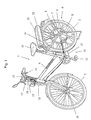
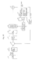
- Fig. 1 is an overall perspective view illustrating an electric bicycle.
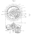
- Fig. 2 is a front view and a side view illustrating a construction of a disk-like casing.
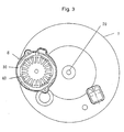
- Fig. 3 is a view illustrating a configuration in which a motor is disposed on the disk-like casing.
- Fig. 4 is a conceptual view showing an electrically assisted bicycle in running.
- Fig. 5 is a graph showing a relationship between the assist ratio and the vehicle speed according to the regulations.
- Fig. 6 is a graph showing a relationship between the assist ratio and the human power torque.
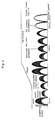
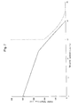
- Fig. 7 is a graph showing motor torque characteristics relative to the vehicle speed which satisfy the regulations.
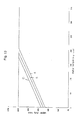
- Fig. 8 is a graph showing motor torque characteristics relative to the vehicle speed before the torque is limited and controlled.
- Fig. 9 is a graph showing an upper duty limit of the pulse width control relative to the motor torque.
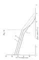
- Fig. 10 is a graph showing motor torque characteristics relative to the vehicle speed after the torque is limited and controlled.
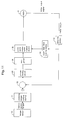
- Fig. 11 is diagram illustrating an embodiment of the torque limiting device for electrically driven vehicles according to the present invention.
- Fig. 12 is a graph showing motor torque characteristics relative to three different vehicle speeds before the torque is limited and controlled.
- Fig. 13 is a graph showing an upper duty limit of the pulse width control relative to the motor torque.
- Fig. 14 is a graph showing motor torque characteristics relative to three different vehicle speeds after the torque is limited and controlled.
- Fig. 15 is a diagram illustrating another embodiment of the torque limiting device for electrically driven vehicles according to the present invention.
- the torque limiting device further comprises a motor torque setting device in which torques of the motor to be limited by the upper electric driving power limit setting device are previously set, whereby the control device is operated on the basis of the output from the motor torque setting device.
- the control device may be, for example, a pulse width modulation control device.
- the electric driving power supplied to the motor is controlled by performing a pulse width modulation control. This makes it possible to limit the output torque of the motor for driving the electrically driven vehicle within a designated range without using a speed sensor.
- the motor output signal indicating the driven state of the motor may be determined by an output current from the battery. This makes it possible to limit the output torque of the motor for driving the electrically driven vehicle within a designated range without using a speed sensor, since the motor output is approximately proportional to the magnitude of the output current from the battery.
- the motor output signal may be determined by an output current from the motor. This makes it possible to limit the output torque of the motor for driving the electrically driven vehicle within a designated range without using a speed sensor, since the motor output is proportional to the magnitude of the output current from the motor.
- the motor output signal may be determined by the torque of the motor to be limited. This makes it possible to limit the output torque of the motor for driving the electrically driven vehicle within a designated range without using a speed sensor.
- the upper electric driving power limit setting device is an upper duty limit setting device, whereby the electric driving power controlled by the control device is restricted on the basis of upper duty ratio limits which are the restricting values.
- the motor is controlled by changing the duty to the motor. This makes it possible to limit the output torque of the motor for driving the electrically driven vehicle within a designated range without using a speed sensor.
- the upper electric driving power limit setting device determines the upper electric driving power limit on the basis of the motor output signal and the power supply voltage designation signal or on the basis of the motor output signal and the motor characteristics designation signal.
- the upper electric driving power limit setting device determines the upper electric driving power limit in accordance with the size of the driving wheel.
- the motor for the electrically driven vehicle may be a motor for an electrically assisted bicycle in which the human driving power is assisted by the motor driving power.
- the output torque of the motor for driving the electrically assisted bicycle can be limited within a designated range even in the case in which a plurality of motors having different characteristics are alternately used or in which a plurality of power supplies having different voltages (for example, batteries) are alternately used for one motor or in which the same torque limiting device of the present invention is mounted onto a plurality of bicycles having driving wheels of different sizes for one motor. Therefore, there will be a large freedom in the adjustment of the characteristics of the motor, the selection of the power supply (batteries), and the selection of the size of the wheels in an electrically assisted bicycle.
- the upper electrical driving power limit setting device preferably determines the upper limit of the electric driving power so that the assist ratio which is a ratio of the motor driving power to the human driving power lies within a restricted range.
- the torque limiting device according to the present invention may be incorporated into an electrically driven vehicle.
- the electrically driven vehicle may be an electrically assisted bicycle in which a human driving power is assisted with a motor driving power.
- Fig. 1 is an overall perspective view of an electric bicycle of direct rear-wheel driving type, in which the reference numeral 1 represents a main body of the electric bicycle.
- a later-mentioned motor 8 is provided in the main body 1 of the electric bicycle so that the driving power of the motor 8 is changed in accordance with the torque generated by the human driving power to assist the human driving power with the driving power of the motor 8 for running the bicycle.
- a front wheel 2, a rear wheel 3, handle bars 13 and a saddle 21 are mounted to a frame 4 of the main body 1 of the electric bicycle.
- the front wheel 2 is steered by the handlebars 13.
- the rear wheel 3 is a driving wheel and a disk-like casing 5 is provided at the rotating shaft of the rear wheel 3.
- the disk-like casing 5 comprises a rotary casing 6 capable of being rotated and a fixed casing 7 fixed onto the main body 1 of the electric bicycle.
- the rotary casing 6 rotates integrally with the rear wheel 3.
- a motor 8 for electric assistance is housed in the disk-like casing 5.
- the motor 8 is driven for rotating the rotary casing 6 together with the later-mentioned human power driving section 10 when an electric driving power is needed.
- the disk-like casing 5 is a part of an electric power driving section 9.
- the human power driving section 10 includes a pedal 11 and a chain 12.
- the pedal 11 When the user presses the pedal 11, the rear wheel 3 is rotated via the chain 12.
- the chain 12 is a member for transmitting the human driving power in this Example, the transmission member is not limited thereto and a belt, a rotating shaft, or the like may be used as well instead of the chain 12.
- Brake levers 14, 15 are mounted to the right and left sides of the handlebars 13 for steering the front wheel 2. Braking devices 18, 19 are provided in the front wheel 2 and the rear wheel 3, respectively. The brake levers 14, 15 and the braking devices 18, 19 are connected by the wires 16, 17.
- a brake switch 20 is provided in the middle of the wires 16, 17 for stopping the supply of electric power to the motor 8 when the brake levers 14, 15 are operated.
- a battery section 22 serving as a power source to the motor 8 is mounted to the frame 4 of the rear wheel 3.
- the battery section 22 includes a battery case 23 and twenty rechargeable batteries of unit-one type stored in the battery case 23.
- the battery case 23 slides on the frame 4 to be attached thereto or detached therefrom.
- the power source voltage is approximately 24 volts.
- the battery case 23 may be disposed at a position other than the frame 4.
- FIG. 2 is a front view illustrating a construction of the disk-like casing 5 shown in Fig. 1, in which the reference numeral 7 represents a fixed casing fixed onto the main body 1 of the electric bicycle.
- the fixed casing 7 houses a control section (not shown), a motor 8, a speed reduction mechanism 26, and a transmission belt 27.
- the control section includes a control substrate, a radiator plate, and the like.
- the speed reduction mechanism 26 includes a pulley pair 25 of a first pulley group 25a and a second pulley group 25b and a last pulley 28 (third pulley) for transmitting an output of the output shaft 24 of the motor 8.
- the transmission belt 27 serves to connect each of the pulleys and the last pulley 28 of the speed reduction mechanism 26.
- the last pulley 28 is fixed onto the rotary casing 6.
- the rotation of the motor 8 is transmitted from the output shaft 24 of the motor 8 to the last pulley 28 via the transmission belt 27, whereby the speed of the rotation is reduced and the rotary casing 6 is rotated together with the last pulley 28.
- the disk-like casing 5 is provided with a torque sensor 41 for detecting a human power torque applied to the pedal 11.
- a human power torque signal from the torque sensor 41 is inputted into the control board.
- the motor 8 is controlled to be driven in accordance with the human power torque signal, for example, by the same driving power.
- a one-way clutch (not shown) is introduced into the smaller pulley of the second pulley group 25b connected to the last pulley 28, whereby the driving power of the motor 8 is cut off when the rotation of the pedal 11 exceeds the rotation of the motor 8.
- Fig. 3 is a front view of a configuration in which the motor 8 is disposed in the disk-like casing 5.
- the reference numeral 30 and 40 represent a stator and a magnet, respectively.
- the torque curve will trespass (i.e. come to the other side of) the boundary line (the broken line) of the condition in the above formula (5) if an assisting motor is used with a relationship between the motor torque and the bicycle speed as shown by the real line of Fig. 8.
- the driving of the assisting motor is controlled by controlling the electric current utilizing the pulse width modulation control (PWM control) in the present invention.
- PWM control pulse width modulation control
- the relationship between the upper duty limit of the pulse width modulation control and the motor torque is set as shown in Fig. 9, it is possible to obtain a relationship between the motor torque and the bicycle speed as shown in Fig. 10.
- the torque curve will lie in the region on the left side of the boundary line (the broken line) of the condition in the formula (5).
- the reference numeral 8 represents a motor for assistance
- 31 represents a motor torque setting device (namely, an assist torque setting device) for setting the driving torque of the motor 8 in accordance with the human power torque detected by the torque sensor 41
- 32 represents a comparator for inputting the motor torque signal by feedback as a signal showing the rotation state of the motor 8 and for comparing the motor torque signal with the value set by the assist torque setting device 31
- 33 represents a proportioning circuit
- 34 represents an integrator
- 35 represents a controlling device (namely, a pulse width modulation (PWM) controlling device) for converting, into a pulse signal, the torque signal prepared for driving the motor 8
- 36 represents an upper driving power limit setting device (namely, an upper duty limit setting device) for setting an upper limit of the driving signal outputted to the motor 8 from the pulse width modulation control device.
- PWM pulse width modulation
- the assist torque setting device 31 there is inputted an assist ratio of the aimed motor torque signal relative to the human power torque detected by the torque sensor of Fig. 6.
- an assist torque instruction signal is outputted in accordance therewith.
- the comparator 32 compares the inputted assist torque instruction signal with the actual fed-back driving torque signal of the motor 8 which is driven.
- the deviation obtained by the above comparison is proportioned and integrated through the proportioning circuit 33 and the integrator 34 and is inputted into the pulse width modulation (PWM) control circuit 35 of the next step to be controlled with a predetermined duty.
- PWM pulse width modulation
- a feed-back control is carried out in which an assist torque instruction signal is generated so that the motor output signal will be 100 Kg ⁇ cm as determined by the assisting torque setting device 31, whereby the assisting torque will be approximated to the desired torque to be outputted as a duty in the pulse width modulation control device 35.
- This Example shows a case in which the switching element is turned on or off to drive the motor 8 by means of PWM control.
- a resistance control method may be employed in which a power transistor is used instead of the switching element and the motor 8 is controlled by varying the voltage applied to the base of the power transistor.
- the motor may be driven without feeding back the motor output.
- the upper duty limit setting device 36 incorporates therein a table showing the relationship between the upper duty limit of the pulse width modulation control and the motor torque shown in Fig. 9.
- the duty of the pulse width modulation control device 35 is limited with a duty corresponding to the motor torque signal by the upper duty limit setting device 36 when the duty is made by the pulse width modulation control device 35 on the basis of a signal from the assisting torque setting device 31.
- the duty is controlled by means of pulse width modulation on the basis of the signal from the assisting torque setting device 31 corresponding to the human power torque until the duty reaches its upper limit.
- the motor torque signal attains the upper limit of the duty as shown in Fig. 9
- the upper limit is inputted into the pulse width modulation control device 35 as the maximum duty, whereby the duty outputted to the motor 8 is restricted.
- a target driving torque signal of the motor 8 is determined by the assisting torque setting device 31 and a duty for driving the motor 8 is made on the basis of the target driving torque signal.
- a motor torque signal is used as the motor output signal indicating the driven state of the motor 8.
- This motor output signal is inputted into the upper duty limit setting device 36 for determination of the upper limit of the duty which is a driving signal. Therefore, when the rotation speed of the motor 8 is small, a comparatively small duty is employed so that the motor output signal will be equal to the target driving torque signal determined by the assisting torque setting device 31.
- the duty when the rotation speed of the motor 8 is large, the duty must be increased in order to allow the motor output signal to be equal to the target driving torque signal determined by the assisting torque setting device 31.
- an upper limit of the duty is determined by the upper duty limit setting device 36, whereby the upper limit of the duty for the pulse width modulation made in the pulse width modulation control device 35 in accordance with the output of the upper duty limit setting device 36 is restricted. Accordingly, the duty for driving the motor 8, which increases in accordance with the increase in the rotation speed of the motor 8 is suppressed. This limits the output torque of the assisting motor 8 of the electrically driven vehicle within a predetermined range without using a speed sensor.
- the motor torque signal is inputted into the upper duty limit setting device 36 for determination of the relationship of the upper duty limit of the pulse width modulation control in this Example
- the signal to be employed is not specifically limited thereto.
- the signal may instead be a motor output signal such as a motor current which is in proportion to the motor torque.
- the signal may be a battery current signal which is correlated to the motor torque or motor output.
- the motor torque of the assisting motor 8 is suppressed so that the motor torque relative to the bicycle speed will have a relation shown in Fig. 10, satisfying the condition of the formula (5) that the torque curve lies in a region on the left side of the boundary line shown by the dotted line. Therefore, the motor output is appropriately controlled on the basis of the motor torque signal without detecting the rotation speed of the motor.
- the above Example shows a case where a motor having specific motor characteristics and a power supply having a specific voltage are used.
- the relationship between the bicycle speed and the motor torque trespasses, at a portion thereof, the boundary line of the condition of the formula (5) shown by the dotted line if three kinds of motors having different motor characteristics are alternately used or three kinds of power supplies having different voltages (for example, batteries) are alternately used for one kind of motor or the same torque limiting device is mounted to three kinds of bicycles having wheels of different sizes, as shown by the real lines (A), (B), and (C) in Fig. 12.
- the driving of the assisting motor is controlled by means of the current control by pulse width modulation control in the present invention.
- a relationship between the motor torque and the bicycle speed as shown in Fig. 14 is obtained if the relationship between the upper duty limit of the pulse width modulation control and the motor torque is set as shown by (A), (B), and (C) of Fig. 13.
- the motor torque at a bicycle speed of about 15 km/h or over is suppressed and the torque curve will lie in a region on the left side of the boundary line of the condition of the formula (5) shown by the dotted line.
- the upper duty limit setting device 36 stores a plurality of tables showing the relationships between the motor torque and the upper duty limit of the pulse width modulation control as illustrated in Fig. 13.
- the duty of the pulse width modulation control device 35 is controlled by a duty corresponding to the motor torque signal.
- the reference numeral 37 represents a motor characteristics designation means, 38 a power supply voltage designation means, and 39 a selection means for the above two designation means.
- the selection means 39 is connected to the motor characteristics designation means 37 in the case where a plurality of motors having different characteristics are to be alternately used.
- the selection means 39 is connected to the power supply voltage designation means 38. This allows selection of a desired table corresponding to the predetermined power supply voltage from the plurality of tables which are stored in the upper duty limit setting device 36 and which show the relationships (A), (B), and (C) between the upper duty limit of the pulse width modulation control and the motor torque.
- the driving of the motor can be controlled with a desired table if the size of the bicycle wheel to be used is set in a table before incorporating the control circuit.
- the sizes of the bicycle wheels correspond to (A), (B), and (C) in the order from the largest size.
- the motor torque of the assisting motor 8 is suppressed so that the motor torque relative to the bicycle speed will have a relation shown in Fig. 14, satisfying the condition of the formula (5) that the torque curve lies in a region on the left side of the boundary line shown by the dotted line. Therefore, the motor output is appropriately controlled to satisfy the condition on the basis of the motor torque signal without detecting the rotation speed of the motor.
- the torque limiting device of the present invention can also be applied to a plurality of bicycles having different gear ratios determined by the front sprocket and the rear sprocket of the bicycle. Further, the torque limiting device can be applied to a bicycle in which a plurality of gear ratios are alternately used for driving the driving wheel.
- the present invention has been described with reference to an example in which the torque of the assisting motor of an electric bicycle is limited, the present invention is not particularly limited to the torque limiting device for electric bicycles but can be applied as a speed limiter for stopping the rotation of the motor when the speed of an electric vehicle or the like exceeds a predetermined value.
- the human power torque shown in the above Examples of Figs. 11 and 15 can be replaced with an ordinary command torque, whereby the assist torque setting device will be unnecessary.
- the other operations are the same as in the above Examples.
- the output torque of the motor for driving an electrically driven vehicle can be limited within a designated range without using a speed sensor in the case where specific motor characteristics and a specific power supply voltage are employed. Further, the output torque of the motor for driving an electrically driven vehicle can be limited within a designated safety range even in the case in which a plurality of motors having different characteristics are alternately used or in which a plurality of power supplies having different voltages (for example, batteries) are alternately used for one motor or in which the same torque limiting device of the present invention is mounted onto a plurality of bicycles having wheels of different sizes.
- the output torque of the motor for driving an electrically assisted bicycle can be limited within a designated range without using a speed sensor, it is possible to prevent excessive and dangerous assistance in which the real output is too large and insufficient assistance in which the real output is too small when the speed determined by the speed sensor is different from the real speed as in the case where a conventional speed sensor is used.
- torque means the magnitude or strength of rotation driving power.
Landscapes
- Engineering & Computer Science (AREA)
- Chemical & Material Sciences (AREA)
- Combustion & Propulsion (AREA)
- Transportation (AREA)
- Mechanical Engineering (AREA)
- Power Engineering (AREA)
- Life Sciences & Earth Sciences (AREA)
- Sustainable Development (AREA)
- Sustainable Energy (AREA)
- Electric Propulsion And Braking For Vehicles (AREA)
Applications Claiming Priority (2)
| Application Number | Priority Date | Filing Date | Title |
|---|---|---|---|
| JP23719196A JP3315872B2 (ja) | 1996-08-20 | 1996-08-20 | 電動車用モータのトルク制限装置 |
| JP237191/96 | 1996-08-20 |
Publications (2)
| Publication Number | Publication Date |
|---|---|
| EP0825102A2 true EP0825102A2 (de) | 1998-02-25 |
| EP0825102A3 EP0825102A3 (de) | 1998-09-09 |
Family
ID=17011726
Family Applications (1)
| Application Number | Title | Priority Date | Filing Date |
|---|---|---|---|
| EP97306340A Withdrawn EP0825102A3 (de) | 1996-08-20 | 1997-08-20 | Drehmoment-Begrenzungseinrichtung für Motoren in elektrisch angetriebenen Fahrzeugen |
Country Status (8)
| Country | Link |
|---|---|
| US (1) | US5971090A (de) |
| EP (1) | EP0825102A3 (de) |
| JP (1) | JP3315872B2 (de) |
| KR (1) | KR100275896B1 (de) |
| CN (1) | CN1117007C (de) |
| CA (1) | CA2213688C (de) |
| ID (1) | ID17429A (de) |
| TW (1) | TW412494B (de) |
Cited By (3)
| Publication number | Priority date | Publication date | Assignee | Title |
|---|---|---|---|---|
| EP2377713A1 (de) * | 2010-04-19 | 2011-10-19 | Sanyo Electric Co., Ltd. | Fahrrad mit elektrischem Hilfsmotor |
| EP2476575A1 (de) * | 2011-01-14 | 2012-07-18 | Pro-Movec A/S | Antriebssteuerung eines elektrisch motorisierten Motorrads |
| EP2664535A1 (de) * | 2012-05-18 | 2013-11-20 | Microspace Corporation | Vorrichtung für Motorsteuerung |
Families Citing this family (42)
| Publication number | Priority date | Publication date | Assignee | Title |
|---|---|---|---|---|
| JP3839199B2 (ja) * | 1999-10-06 | 2006-11-01 | 本田技研工業株式会社 | ハイブリッド車両の制御装置 |
| US6588528B2 (en) * | 2001-08-01 | 2003-07-08 | Electric Transportation Company | Electric vehicle drive system |
| AT500328B1 (de) * | 2002-02-07 | 2010-03-15 | Elin Ebg Traction Gmbh | Fahrzeug mit einem elektrischen antrieb und verfahren zum betrieb eines solchen fahrzeuges |
| FR2879526B1 (fr) * | 2004-12-20 | 2008-05-30 | Renault Sas | Procede d'aide au demarrage d'un vehicule automobile et dispositif associe |
| US9050903B2 (en) * | 2007-02-28 | 2015-06-09 | GM Global Technology Operations LLC | Torque control arbitration in powertrain systems |
| JP4895877B2 (ja) * | 2007-03-16 | 2012-03-14 | 三洋電機株式会社 | 電動車輌 |
| CN101355335B (zh) * | 2007-07-24 | 2010-12-01 | 南京大陆鸽高科技股份有限公司 | 一种直流电动机数字动态力矩闭环控制系统 |
| US7598683B1 (en) | 2007-07-31 | 2009-10-06 | Lsi Industries, Inc. | Control of light intensity using pulses of a fixed duration and frequency |
| US8604709B2 (en) | 2007-07-31 | 2013-12-10 | Lsi Industries, Inc. | Methods and systems for controlling electrical power to DC loads |
| US8903577B2 (en) | 2009-10-30 | 2014-12-02 | Lsi Industries, Inc. | Traction system for electrically powered vehicles |
| JP4841676B2 (ja) | 2010-03-17 | 2011-12-21 | パナソニック株式会社 | 電動アシスト自転車用モータ制御方法および電動アシスト自転車用モータ制御装置 |
| CN102219042A (zh) * | 2010-04-19 | 2011-10-19 | 三洋电机株式会社 | 电动辅助自行车 |
| DE102010028658A1 (de) * | 2010-05-06 | 2011-11-10 | Robert Bosch Gmbh | Verfahren und Vorrichtung zur automatischen Steuerung des Gangs eines Elektrofahrrad-Getriebes |
| EP2657118B1 (de) * | 2010-12-22 | 2021-03-03 | Microspace Corporation | Motorantriebssteuervorrichtung |
| US9162730B2 (en) | 2010-12-22 | 2015-10-20 | Microspace Corporation | Motor driving control apparatus |
| DE102011077181A1 (de) * | 2011-06-08 | 2012-12-13 | Robert Bosch Gmbh | Verfahren und Vorrichtung zur Verschleißerkennung an einem Elektrofahrrad |
| US20140137527A1 (en) * | 2011-07-12 | 2014-05-22 | Yanmar Co., Ltd. | Mobile Electric Work Machine |
| JP5575938B1 (ja) * | 2013-02-07 | 2014-08-20 | 株式会社シマノ | 自転車用制御装置 |
| US20150088347A1 (en) * | 2013-09-26 | 2015-03-26 | Tseng-Fu Yeh | Driving mode switching device for electric gear box |
| US8925668B1 (en) * | 2014-01-24 | 2015-01-06 | Marvin Mofield | Bicycle with power assisting function |
| US9637197B2 (en) * | 2015-07-01 | 2017-05-02 | GM Global Technology Operations LLC | Dynamic inertia compensation and pedal effort transformation for electric bike |
| JP6894195B2 (ja) * | 2016-06-14 | 2021-06-30 | 株式会社シマノ | 自転車用表示装置 |
| JP6735158B2 (ja) * | 2016-06-14 | 2020-08-05 | 株式会社シマノ | 自転車用制御装置 |
| EP3646836B1 (de) * | 2017-06-26 | 2021-10-06 | Yamaha Hatsudoki Kabushiki Kaisha | Rollstuhl mit elektrischem hilfsantrieb, elektrische hilfsantriebseinheit für rollstuhl, steuervorrichtung für rollstuhl mit elektrischem hilfsantrieb, steuerverfahren für rollstuhl mit elektrischem hilfsantrieb und programm |
| JP6831314B2 (ja) * | 2017-09-29 | 2021-02-17 | 株式会社シマノ | 自転車用制御装置 |
| JP7343266B2 (ja) * | 2017-10-27 | 2023-09-12 | 株式会社シマノ | 人力駆動車両用制御装置 |
| JP6927902B2 (ja) * | 2018-02-09 | 2021-09-01 | 株式会社シマノ | 人力駆動車両用制御装置 |
| JP6993272B2 (ja) | 2018-03-22 | 2022-01-13 | 株式会社シマノ | 人力駆動車両用制御装置 |
| JP6867325B2 (ja) * | 2018-03-22 | 2021-04-28 | 株式会社シマノ | 人力駆動車両用制御装置 |
| JP6959170B2 (ja) | 2018-03-22 | 2021-11-02 | 株式会社シマノ | 人力駆動車両用制御装置 |
| JP7048388B2 (ja) | 2018-03-29 | 2022-04-05 | 株式会社シマノ | 人力駆動車用制御装置 |
| JP7244240B2 (ja) * | 2018-09-26 | 2023-03-22 | 株式会社シマノ | 人力駆動車用制御装置 |
| JP6916140B2 (ja) | 2018-03-29 | 2021-08-11 | 株式会社シマノ | 人力駆動車用制御装置 |
| US11584476B2 (en) * | 2018-08-14 | 2023-02-21 | Msns, Llc | Electric bicycle motor system |
| JP7021031B2 (ja) * | 2018-08-23 | 2022-02-16 | 株式会社シマノ | 人力駆動車用制御装置 |
| JP7293417B2 (ja) * | 2018-08-23 | 2023-06-19 | 株式会社シマノ | 人力駆動車用制御装置 |
| JP7078500B2 (ja) | 2018-09-10 | 2022-05-31 | 株式会社シマノ | 人力駆動車用制御装置 |
| JP7277120B2 (ja) | 2018-12-03 | 2023-05-18 | 株式会社シマノ | 人力駆動車用の制御装置 |
| DE102020200198A1 (de) * | 2019-02-01 | 2020-08-06 | Robert Bosch Gesellschaft mit beschränkter Haftung | Betriebsverfahren und Steuereinheit für einen Antrieb eines Fahrzeugs und Fahrzeug |
| JP7514605B2 (ja) | 2019-05-17 | 2024-07-11 | 株式会社シマノ | 人力駆動車用の制御装置 |
| JP7344507B2 (ja) * | 2019-09-13 | 2023-09-14 | 株式会社モルテン | 車いすの駆動補助機構 |
| US20210114686A1 (en) * | 2019-10-21 | 2021-04-22 | GM Global Technology Operations LLC | System and method for controlling an electric bicycle |
Citations (1)
| Publication number | Priority date | Publication date | Assignee | Title |
|---|---|---|---|---|
| JPH06107266A (ja) | 1992-09-30 | 1994-04-19 | Yamaha Motor Co Ltd | 電動モータ付き自転車 |
Family Cites Families (12)
| Publication number | Priority date | Publication date | Assignee | Title |
|---|---|---|---|---|
| US5237263A (en) * | 1991-06-17 | 1993-08-17 | Gannon Henry M | Electric and pedal driven bicycle with solar charging |
| ES2112347T3 (es) * | 1992-03-19 | 1998-04-01 | Sanyo Electric Co | Bicicleta accionada por un motor y pedales. |
| US5370200A (en) * | 1992-05-11 | 1994-12-06 | Yamaha Hatsudoki Kabushiki Kaisha | Bicycle with electric motor |
| IT1270446B (it) * | 1993-02-11 | 1997-05-05 | Fiat Auto Spa | Procedimento e dispositivo per l'utilizzazione ottimizzata delle batterie di trazione di un veicolo elettrico. |
| TW467091U (en) * | 1994-03-29 | 2001-12-01 | Sanyo Electric Co | Electric bicycle |
| JP3276782B2 (ja) * | 1994-08-18 | 2002-04-22 | 本田技研工業株式会社 | 電動補助自転車 |
| JP3138795B2 (ja) * | 1994-09-12 | 2001-02-26 | 本田技研工業株式会社 | 自転車用アシストモータの制御方法 |
| CN2213111Y (zh) * | 1994-11-30 | 1995-11-22 | 张道德 | 一种电动轻便车 |
| TW308754B (de) * | 1994-12-28 | 1997-06-21 | Yamaha Motor Co Ltd | |
| TW404383U (en) * | 1995-02-28 | 2000-09-01 | Sanyo Electric Co | Electric bicycle |
| US5758736A (en) * | 1995-03-29 | 1998-06-02 | Suzuki Kabushiki Kaisha | Power assist apparatus of power assisted bicycle |
| JP3691132B2 (ja) * | 1995-10-31 | 2005-08-31 | 三洋電機株式会社 | アシスト式乗り物 |
-
1996
- 1996-08-20 JP JP23719196A patent/JP3315872B2/ja not_active Expired - Fee Related
-
1997
- 1997-07-31 TW TW086110964A patent/TW412494B/zh not_active IP Right Cessation
- 1997-08-14 KR KR1019970038987A patent/KR100275896B1/ko not_active Expired - Fee Related
- 1997-08-18 ID IDP972883A patent/ID17429A/id unknown
- 1997-08-19 US US08/918,591 patent/US5971090A/en not_active Expired - Fee Related
- 1997-08-19 CA CA002213688A patent/CA2213688C/en not_active Expired - Fee Related
- 1997-08-20 EP EP97306340A patent/EP0825102A3/de not_active Withdrawn
- 1997-08-20 CN CN97117412A patent/CN1117007C/zh not_active Expired - Fee Related
Patent Citations (1)
| Publication number | Priority date | Publication date | Assignee | Title |
|---|---|---|---|---|
| JPH06107266A (ja) | 1992-09-30 | 1994-04-19 | Yamaha Motor Co Ltd | 電動モータ付き自転車 |
Cited By (5)
| Publication number | Priority date | Publication date | Assignee | Title |
|---|---|---|---|---|
| EP2377713A1 (de) * | 2010-04-19 | 2011-10-19 | Sanyo Electric Co., Ltd. | Fahrrad mit elektrischem Hilfsmotor |
| EP2476575A1 (de) * | 2011-01-14 | 2012-07-18 | Pro-Movec A/S | Antriebssteuerung eines elektrisch motorisierten Motorrads |
| WO2012095528A3 (en) * | 2011-01-14 | 2012-12-27 | Pro-Movec A/S | Drive control of an electrically motorised bicycle |
| EP2664535A1 (de) * | 2012-05-18 | 2013-11-20 | Microspace Corporation | Vorrichtung für Motorsteuerung |
| US9114850B2 (en) | 2012-05-18 | 2015-08-25 | Microspace Corporation | Motor drive control device |
Also Published As
| Publication number | Publication date |
|---|---|
| JP3315872B2 (ja) | 2002-08-19 |
| EP0825102A3 (de) | 1998-09-09 |
| CA2213688A1 (en) | 1998-02-20 |
| ID17429A (id) | 1997-12-24 |
| KR19980018707A (ko) | 1998-06-05 |
| KR100275896B1 (ko) | 2000-12-15 |
| CN1174792A (zh) | 1998-03-04 |
| TW412494B (en) | 2000-11-21 |
| US5971090A (en) | 1999-10-26 |
| JPH1059260A (ja) | 1998-03-03 |
| CN1117007C (zh) | 2003-08-06 |
| CA2213688C (en) | 2001-03-27 |
Similar Documents
| Publication | Publication Date | Title |
|---|---|---|
| US5971090A (en) | Torque limiting device for motors in electically driven vehicles and electrically driven vehicle incorporation the torque limiting device | |
| US12330733B2 (en) | Human-powered vehicle control device | |
| US20050252706A1 (en) | An All-Terrain Electronically Powered Vehicle And Temperature Sensing Motor Controller For Use Therein | |
| JP3086475B2 (ja) | 電動モータ付き人力駆動装置 | |
| US5819867A (en) | Electrically powered bicycle | |
| JP2005102463A (ja) | 四輪駆動装置及びその駆動方法 | |
| ATE202525T1 (de) | Elektrischer fahrrad-hilfsantrieb | |
| JP2010264977A (ja) | 電動アシスト自転車 | |
| JPH1059262A (ja) | 電気自転車用モータの出力制御方式 | |
| KR100917586B1 (ko) | 하이브리드 자전거 | |
| JPH1081290A (ja) | トルク補助式電動自転車 | |
| JPS649063A (en) | Electrical power steering device | |
| JP2000142544A (ja) | 電動走行車両 | |
| JP4623864B2 (ja) | 電動アシスト自転車 | |
| JP3530252B2 (ja) | 電動自転車 | |
| JP3780141B2 (ja) | 電動パワーステアリング制御装置 | |
| JP2000103383A (ja) | 補助動力付き車両 | |
| JPS6338031A (ja) | 自動車の補助駆動装置 | |
| JP2000168387A (ja) | 電動駆動力アシスト車両 | |
| JP3499948B2 (ja) | 電動自転車 | |
| JPH0848279A (ja) | 動力自転車 | |
| US20240359771A1 (en) | Method for the Open-Loop Control of a Drive Device | |
| JPH11105778A (ja) | 自転車用補助駆動モータの制御装置 | |
| KR100250873B1 (ko) | 타여자 직류 전동기 제어기 및 그 제어방법(separatedly exited controller and the control method) | |
| JP3814680B2 (ja) | 電動式パワーステアリングシステム |
Legal Events
| Date | Code | Title | Description |
|---|---|---|---|
| PUAI | Public reference made under article 153(3) epc to a published international application that has entered the european phase |
Free format text: ORIGINAL CODE: 0009012 |
|
| AK | Designated contracting states |
Kind code of ref document: A2 Designated state(s): AT BE CH DE ES FR GB IT LI NL SE |
|
| AX | Request for extension of the european patent |
Free format text: AL;LT;LV;RO;SI |
|
| PUAL | Search report despatched |
Free format text: ORIGINAL CODE: 0009013 |
|
| AK | Designated contracting states |
Kind code of ref document: A3 Designated state(s): AT BE CH DE DK ES FI FR GB GR IE IT LI LU MC NL PT SE |
|
| AX | Request for extension of the european patent |
Free format text: AL;LT;LV;RO;SI |
|
| 17P | Request for examination filed |
Effective date: 19981023 |
|
| AKX | Designation fees paid |
Free format text: AT BE CH DE ES FR GB IT LI NL SE |
|
| RBV | Designated contracting states (corrected) |
Designated state(s): AT BE CH DE ES FR GB IT LI NL SE |
|
| 17Q | First examination report despatched |
Effective date: 20020806 |
|
| GRAP | Despatch of communication of intention to grant a patent |
Free format text: ORIGINAL CODE: EPIDOSNIGR1 |
|
| STAA | Information on the status of an ep patent application or granted ep patent |
Free format text: STATUS: THE APPLICATION IS DEEMED TO BE WITHDRAWN |
|
| 18D | Application deemed to be withdrawn |
Effective date: 20051028 |