EP0819086B1 - Procede et dispositif pour la fabrication d'une boite munie d'une membrane de fermeture en feuille, ainsi que boite semi-finie munie d'une membrane de fermeture en feuille - Google Patents
Procede et dispositif pour la fabrication d'une boite munie d'une membrane de fermeture en feuille, ainsi que boite semi-finie munie d'une membrane de fermeture en feuille Download PDFInfo
- Publication number
- EP0819086B1 EP0819086B1 EP96910945A EP96910945A EP0819086B1 EP 0819086 B1 EP0819086 B1 EP 0819086B1 EP 96910945 A EP96910945 A EP 96910945A EP 96910945 A EP96910945 A EP 96910945A EP 0819086 B1 EP0819086 B1 EP 0819086B1
- Authority
- EP
- European Patent Office
- Prior art keywords
- foil
- stamp
- edge region
- raised
- membrane
- Prior art date
- Legal status (The legal status is an assumption and is not a legal conclusion. Google has not performed a legal analysis and makes no representation as to the accuracy of the status listed.)
- Expired - Lifetime
Links
- 239000012528 membrane Substances 0.000 title claims abstract description 46
- 239000011888 foil Substances 0.000 title claims abstract description 40
- ATJFFYVFTNAWJD-UHFFFAOYSA-N Tin Chemical compound [Sn] ATJFFYVFTNAWJD-UHFFFAOYSA-N 0.000 title claims abstract description 9
- 238000000034 method Methods 0.000 title claims description 22
- 230000008569 process Effects 0.000 title claims description 13
- 238000004519 manufacturing process Methods 0.000 title claims description 5
- 239000004033 plastic Substances 0.000 claims abstract description 4
- 229910052751 metal Inorganic materials 0.000 claims description 9
- 239000002184 metal Substances 0.000 claims description 9
- 238000003892 spreading Methods 0.000 claims description 9
- 230000007480 spreading Effects 0.000 claims description 9
- 239000004831 Hot glue Substances 0.000 claims description 5
- 239000000853 adhesive Substances 0.000 claims description 5
- 230000001070 adhesive effect Effects 0.000 claims description 5
- 238000010438 heat treatment Methods 0.000 claims description 4
- 230000009471 action Effects 0.000 claims description 3
- 239000000123 paper Substances 0.000 claims description 3
- 238000006073 displacement reaction Methods 0.000 claims 4
- 239000002985 plastic film Substances 0.000 claims 1
- 229920006255 plastic film Polymers 0.000 claims 1
- 238000007789 sealing Methods 0.000 abstract description 8
- 239000010408 film Substances 0.000 description 41
- 229910052782 aluminium Inorganic materials 0.000 description 5
- XAGFODPZIPBFFR-UHFFFAOYSA-N aluminium Chemical compound [Al] XAGFODPZIPBFFR-UHFFFAOYSA-N 0.000 description 5
- 239000010409 thin film Substances 0.000 description 4
- 238000011109 contamination Methods 0.000 description 3
- 230000037303 wrinkles Effects 0.000 description 3
- 238000004026 adhesive bonding Methods 0.000 description 2
- 238000013459 approach Methods 0.000 description 2
- 230000008901 benefit Effects 0.000 description 2
- 239000011248 coating agent Substances 0.000 description 2
- 238000000576 coating method Methods 0.000 description 2
- 230000006378 damage Effects 0.000 description 2
- 239000013067 intermediate product Substances 0.000 description 2
- 239000004922 lacquer Substances 0.000 description 2
- 239000000463 material Substances 0.000 description 2
- 238000012549 training Methods 0.000 description 2
- 208000027418 Wounds and injury Diseases 0.000 description 1
- 239000011324 bead Substances 0.000 description 1
- 230000015572 biosynthetic process Effects 0.000 description 1
- 229910010293 ceramic material Inorganic materials 0.000 description 1
- 230000006835 compression Effects 0.000 description 1
- 238000007906 compression Methods 0.000 description 1
- 238000002788 crimping Methods 0.000 description 1
- 238000005520 cutting process Methods 0.000 description 1
- 230000000881 depressing effect Effects 0.000 description 1
- 238000013461 design Methods 0.000 description 1
- 238000011161 development Methods 0.000 description 1
- 230000018109 developmental process Effects 0.000 description 1
- 230000000694 effects Effects 0.000 description 1
- 238000005338 heat storage Methods 0.000 description 1
- 208000014674 injury Diseases 0.000 description 1
- 238000009434 installation Methods 0.000 description 1
- 238000005304 joining Methods 0.000 description 1
- 239000007788 liquid Substances 0.000 description 1
- 230000001404 mediated effect Effects 0.000 description 1
- 238000012986 modification Methods 0.000 description 1
- 230000004048 modification Effects 0.000 description 1
- 238000003825 pressing Methods 0.000 description 1
- 239000000047 product Substances 0.000 description 1
- 238000004080 punching Methods 0.000 description 1
- 238000000926 separation method Methods 0.000 description 1
- 239000005028 tinplate Substances 0.000 description 1
- 238000003466 welding Methods 0.000 description 1
Images
Classifications
-
- B—PERFORMING OPERATIONS; TRANSPORTING
- B65—CONVEYING; PACKING; STORING; HANDLING THIN OR FILAMENTARY MATERIAL
- B65B—MACHINES, APPARATUS OR DEVICES FOR, OR METHODS OF, PACKAGING ARTICLES OR MATERIALS; UNPACKING
- B65B7/00—Closing containers or receptacles after filling
- B65B7/16—Closing semi-rigid or rigid containers or receptacles not deformed by, or not taking-up shape of, contents, e.g. boxes or cartons
- B65B7/28—Closing semi-rigid or rigid containers or receptacles not deformed by, or not taking-up shape of, contents, e.g. boxes or cartons by applying separate preformed closures, e.g. lids, covers
- B65B7/2842—Securing closures on containers
- B65B7/2878—Securing closures on containers by heat-sealing
-
- B—PERFORMING OPERATIONS; TRANSPORTING
- B65—CONVEYING; PACKING; STORING; HANDLING THIN OR FILAMENTARY MATERIAL
- B65D—CONTAINERS FOR STORAGE OR TRANSPORT OF ARTICLES OR MATERIALS, e.g. BAGS, BARRELS, BOTTLES, BOXES, CANS, CARTONS, CRATES, DRUMS, JARS, TANKS, HOPPERS, FORWARDING CONTAINERS; ACCESSORIES, CLOSURES, OR FITTINGS THEREFOR; PACKAGING ELEMENTS; PACKAGES
- B65D51/00—Closures not otherwise provided for
- B65D51/18—Arrangements of closures with protective outer cap-like covers or of two or more co-operating closures
- B65D51/20—Caps, lids, or covers co-operating with an inner closure arranged to be opened by piercing, cutting, or tearing
-
- B—PERFORMING OPERATIONS; TRANSPORTING
- B21—MECHANICAL METAL-WORKING WITHOUT ESSENTIALLY REMOVING MATERIAL; PUNCHING METAL
- B21D—WORKING OR PROCESSING OF SHEET METAL OR METAL TUBES, RODS OR PROFILES WITHOUT ESSENTIALLY REMOVING MATERIAL; PUNCHING METAL
- B21D51/00—Making hollow objects
- B21D51/16—Making hollow objects characterised by the use of the objects
- B21D51/26—Making hollow objects characterised by the use of the objects cans or tins; Closing same in a permanent manner
-
- B—PERFORMING OPERATIONS; TRANSPORTING
- B65—CONVEYING; PACKING; STORING; HANDLING THIN OR FILAMENTARY MATERIAL
- B65D—CONTAINERS FOR STORAGE OR TRANSPORT OF ARTICLES OR MATERIALS, e.g. BAGS, BARRELS, BOTTLES, BOXES, CANS, CARTONS, CRATES, DRUMS, JARS, TANKS, HOPPERS, FORWARDING CONTAINERS; ACCESSORIES, CLOSURES, OR FITTINGS THEREFOR; PACKAGING ELEMENTS; PACKAGES
- B65D2251/00—Details relating to container closures
- B65D2251/0003—Two or more closures
- B65D2251/0006—Upper closure
- B65D2251/0018—Upper closure of the 43-type
-
- B—PERFORMING OPERATIONS; TRANSPORTING
- B65—CONVEYING; PACKING; STORING; HANDLING THIN OR FILAMENTARY MATERIAL
- B65D—CONTAINERS FOR STORAGE OR TRANSPORT OF ARTICLES OR MATERIALS, e.g. BAGS, BARRELS, BOTTLES, BOXES, CANS, CARTONS, CRATES, DRUMS, JARS, TANKS, HOPPERS, FORWARDING CONTAINERS; ACCESSORIES, CLOSURES, OR FITTINGS THEREFOR; PACKAGING ELEMENTS; PACKAGES
- B65D2251/00—Details relating to container closures
- B65D2251/0003—Two or more closures
- B65D2251/0068—Lower closure
- B65D2251/0093—Membrane
-
- B—PERFORMING OPERATIONS; TRANSPORTING
- B65—CONVEYING; PACKING; STORING; HANDLING THIN OR FILAMENTARY MATERIAL
- B65D—CONTAINERS FOR STORAGE OR TRANSPORT OF ARTICLES OR MATERIALS, e.g. BAGS, BARRELS, BOTTLES, BOXES, CANS, CARTONS, CRATES, DRUMS, JARS, TANKS, HOPPERS, FORWARDING CONTAINERS; ACCESSORIES, CLOSURES, OR FITTINGS THEREFOR; PACKAGING ELEMENTS; PACKAGES
- B65D2577/00—Packages formed by enclosing articles or materials in preformed containers, e.g. boxes, cartons, sacks, bags
- B65D2577/10—Container closures formed after filling
- B65D2577/20—Container closures formed after filling by applying separate lids or covers
- B65D2577/2041—Pull tabs
- B65D2577/2058—Pull tabs attached to the closure
Definitions
- the invention relates to a method and an apparatus for Production of a can according to the preamble of claim 1 or Claims 7 and 8, and a semi-finished tin made of sheet metal with a Membrane film closure.
- Tin cans have so far been essentially either joint crimping of the can cut edge with a metal lid sealed (e.g. according to WO 83/02577 or US-A-3,952,677), or with provided with a sheet metal ring provided with foil (according to AT-A-368.919), or the inside of the can wall (1) had to - at least in the area of the raised foil edge area (5) - be conical (e.g. according to DE-U-94 14 440), which is a more complicated can production and high Tolerances required so that when the stamp was retracted, it was always the same The position of the membrane plate in relation to the edge of the can could be achieved.
- the cut edge of the can is not overlapping plates raised edge for cans made of plastic (e.g. DE-A1-33 05 144 or CH-A-629 984), but this was always the case relatively stable lid parts for the bottom of pressure-resistant cans or those from relatively soft walls (e.g. according to US-A-4,599,123), which for Sealing process required an external pressure recording device.
- plastic e.g. DE-A1-33 05 144 or CH-A-629 984
- WO-A-84/04507 has already described a device in which the sealing of a can is carried out by means of a membrane film a mechanically stretched rubber ring to the The inner wall of the can is pressed and with a hot glue is connected.
- this requires a very complicated training of the Rubber ring and that from the outside to the can wall Welding tool.
- the object of the invention is now a process for the production a tin can, especially one made of tinplate or Aluminum sheet, with a simple and above all cheap closure too create. This is achieved for the first time by the in the characterizing part of claim 1 mentioned feature. Preferred developments of the invention Procedures are described in the characterizing part of claims 2 and 3.
- the closure is there - as is known in another context become - from only one membrane film, possibly from (especially with thin aluminum foil laminated) paper and / or plastic, but preferably a metal foil, especially aluminum, all in following for the sake of simplicity also referred to as membrane film, and if necessary, in a manner known per se, with the aid of Tear tabs to expose the can opening.
- the edge of the membrane plate which is pulled up, extends over the - preferably flanged - can edge does not make it easier Tear open and therefore leaves the edge of the can its robust outside or Footprint.
- the membrane film is preferably at most 0.2 mm, in particular at most 0.1 mm thick, e.g. from a 50 ⁇ aluminum foil with 20 ⁇ Heat seal coating on the inside and 10-20 ⁇ anti-friction coating on the outside and is therefore for the closure of the later Removal opening suitable.
- the lid can also be used if necessary be produced according to the invention. Use is also preferred of embossed foils, because they are easier on cans with changing Let tolerance nestle and also result in better stability.
- the membrane film - at least in the area intended for connection to the inner wall of the box - with is coated with a heat seal lacquer.
- Inner wall of the can in the area mentioned - such as that of (e.g. combination cans coated with aluminum foil - with a primer or a heat sealable layer; otherwise the density requires Connection often the use of special - especially multi-component - Adhesives or heat seal lacquers. In any case, it can also be bare or lacquered tin cans are sealed.
- the method according to the invention is particularly suitable the device according to claim 7 or 8. Special embodiments described in the characterizing part of claims 9 and 10.
- a tin can has become known from CH-PS 659.633, the end face of which is closed with a raised membrane.
- a heat-conducting lid that remains in the can until it is opened by the last consumer (FIG. 9), whereupon the membrane is also removed and the can no longer meets the requirements.
- the semi-finished can according to claim 11 is now only closed at one end with a membrane film and there free of a heat-conducting lid (as is customary in the industry, and is therefore suitable for filling on the opposite side, i.e. an intermediate product, while the comparable one Intermediate product according to CH-PS 659.633 has such a heat-conducting lid, which makes the can more expensive and more difficult).
- the film used according to the invention is relatively thin and preferably a film with good thermal conductivity to use a hot joining process, such as one Apply hot glue to the outside.
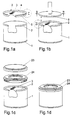
- a can 1 made of sheet metal with a Membrane film 2 are closed.
- the membrane film 2 can with a tear tab 3 connected in any way, for example by gluing be.
- the tab 3 can do this can be used, the introduced into the box 1 and connected to it at the edge Tear off membrane film 2 as a whole.
- This is cheaper because in the conventional design either a predetermined breaking point, e.g. by Punching, or a separation of the membrane film edge overlapping the can cutting edge created by the membrane foil plate spanning the can opening had to become.
- the membrane plate part spanning the can opening provides a certain stiffening mediated.
- the membrane film closing the can base preferably has 2 for stiffening (and also for achieving a slight radial Elasticity during deep drawing and / or sealing) preferably at least one circular bead.
- the membrane film 2 reinforced in this way can now form-fitting (so that the film shape does not when inserted into the can opening is changed), e.g. by means of a suction gripper known per se and be placed on the top of the can 1 in a first step.
- the raised edge is at least slightly conically divergent, i.e. it results in a vertical V, if only very small, but it does measurable angle ß, the size of less than 5 °, in particular less than 2 °.
- the diameter at the bottom of the membrane plate i.e. in the area of the cover surface 4 only a few tenths of a mm smaller than the opening diameter of the membrane plate , the height measured along the vertical V being only about 5 mm must be.
- the upper, larger diameter of the membrane film 2 becomes natural expediently chosen so that they are frictionally engaged when placed on by the suction pad is held at the top of the can 1.
- Another measure to secure the membrane sheet 2 on the top of the can 1 can in consist of a cross-section hook-shaped collar 6, which with the upper Edge of can 1 interacts.
- the upper, mostly sharp-edged edge of the can Incidentally, 1 is preferably flanged to the outside (7 in Fig. 1a, 3) to a Prevent damage to the thin film or injury to the user.
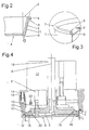
- the stamp 8 is in accordance with FIG Fig.4 section shown. It consists of several parts, namely the actual stamp surface 9, which protrudes upwards from the pin 10 (only one is shown, preferably there are three) with the approach 11 of a stamp head 12 is connected. There is a centering ring 13 around the stamp surface 9 placed along guide pins 14 and against the effect at least a compression spring 15 is displaceable. Usually the ring takes 13 the left in Fig.4, lowered position, in which it is not, for example supported on the top of the stamp surface 9, if necessary but is also held by other means.
- the centering ring 13 takes up the edge of the can and has a recess 13 'for this purpose.
- the process can now proceed that the can 1 is on a lifting table and is lifted up, whereby the centering ring 13 against the action of the spring 15 in the one shown on the right top layer shifts.
- the stamp surface 9 emerges from the inside of the Ring 13 and thus presses the membrane film 2 in that shown in Fig.1b and 3 Location.
- the ring 13 could also be stationary and hold the can centered, while the stamp surface 9 is moved down.
- the approach 11 as a piston rod of a fluidic unit, preferably of a pneumatic piston-cylinder unit. It it goes without saying, however, that constructive considerations leave a lot of leeway is granted, since it is only on the relative movement of the parts shown and the Can arrives.
- the centering of the can or relative to it could also Membrane film 2 done in a variety of ways.
- the stamp 8 has a spreading device which in the embodiment of Figure 4 is formed by a wedge arrangement. Along a row of wedge segments 16 is guided at the top of the stamp surface 9, that they are radially outward with respect to the central axis A of the punch 8 can be moved.
- the back of the stamp surface could be used for guidance 9, for example, have grooves or slots (not shown). It however, the flat back of the stamp surface may also be sufficient for guidance.
- wedge segments 16 on themselves to press the hoisted Film edge area 5 of the membrane film 2 is used on the inner circumference of the can 1 , it is advantageous if they are made of elastic piston rings 17 or circlips can be spanned. This creates a more even one Circumferential surface when pressing these rings 17 against the film edge area 5 of the membrane film 2 and also results in a double function Restoring force that acts on the segments 16.
- a conical wedge 18 In order to press the wedge segments 16 radially outwards, there is a conical wedge 18 provided, preferably by means of an actuating rod 19 of a drive pneumatic type, downwards and between the wedge segments with their Wedge surfaces 20 can be moved.
- the reason for preferring one pneumatic drive is that there is a risk of contamination is hardly given by oil or leakage liquid and a maximum pressure is particularly easy can be set that does not expand the can. If the conical wedge 18 is moved down against the stamp surface 9, it spreads the Wedge segments 16 apart and thus presses the elastic rings 17 against the film edge area 5 outwards, where the can rim is stuck in the recess 13 '. To this The position of the membrane film 2 according to FIG. 1b is achieved.
- the membrane film 2 must also be secured and in general also be sealed. This can be done in a conventional manner Gluing, preferably done by means of heat sealing, because of the thin membrane film 2 yes the heat lets through relatively well.
- Gluing preferably done by means of heat sealing, because of the thin membrane film 2 yes the heat lets through relatively well.
- the outside the edge of the film may be coated with a hot glue 21 (FIG. 2).
- a heating device is then assigned to the spreading device 16-18. This could formed by heating coils accommodated in the wedge segments 16 be, but the space is very narrow at this point, and still movable Connections are to be provided. So although this possibility is not excluded may be a (e.g. annular) radiant heat source 22, e.g.
- wedge segments 16 and the rings 17 are provided which heat these parts, to heat the hot glue 21 (Fig.2) and with the inner wall of the Merge can 1.
- the wedge segments 16 can for example consist of one Ceramic material with good heat storage properties can be formed, which also improves wear properties.
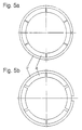
- 5a shows the wedge segments 16 and a snap ring 17 in the closed, 5b (through the wedge pieces 18 of the not shown here, perpendicular to the plane of the drawing moving stamp 8) in the spread position for the purpose of heat sealing the membrane film 2 to the inner wall of the can.
- the wedge arrangement shown is only one possible, under certain circumstances preferred embodiment with regard to the life of the device is and that numerous modifications within the scope of the invention are conceivable.
- the tapered wedge 18 could be simply relative be formed to the stamp surface 9 movable pressure plate, wherein between a rubber bellows is provided on the top of the stamp surface 9 and this pressure plate may be.
- a horizontal drive, radially outwards, would also be suitable for the individual segments 16 conceivable, but structurally complex.
- the upper edge of the can may be heated represent the simpler solution from the outside for the purpose of heat sealing.
- a cover 23 or 24 (Fig.1c) can be applied will.
- a particular advantage of the present invention is that the Foils can be manufactured separately and if necessary kept in stock, where - with the same diameter of the cans 1 - cans with different Volume with the prefabricated and due to their training with the foil edge area 5 but sufficiently stable foils 2 can be loaded.
- This Film edge area 5 can also be easily coated with the adhesive 21, which is difficult to attach to the inner circumference of the can due to the risk of contamination would.
- the invention is of course not based on the use of an adhesive, as already explained.
- the output of the device according to the invention can be - e.g. on a rotary table arranged - multiple tools in a conventional manner be increased.
Landscapes
- Engineering & Computer Science (AREA)
- Mechanical Engineering (AREA)
- Closures For Containers (AREA)
- Laminated Bodies (AREA)
- Rigid Containers With Two Or More Constituent Elements (AREA)
- Closing Of Containers (AREA)
- Making Paper Articles (AREA)
- Wrappers (AREA)
- Electroplating Methods And Accessories (AREA)
- Separation Using Semi-Permeable Membranes (AREA)
- Lining Or Joining Of Plastics Or The Like (AREA)
Claims (12)
- Procédé de fabrication d'une boite en tôle métallique, avec une feuille formant membrane (2) prévue sur au moins une face frontale, en papier, en matière synthétique ou en métal, introduite dans la boite, avec une zone de bordure de feuille (5) relevée, et obturant au moins une face frontale, de manière que la face extérieure de la zone de bordure de feuille (5) relevée dans la direction de l'axe de boite (A) soit reliée avec effet d'étanchéité à la face intérieure, de réalisation sensiblement cylindrique - au moins dans la région de la zone de bordure de feuille (5) relevée - de la paroi de boite (1), de préférence par collage ou par scellage à chaud, caractérisé en ce que la feuille formant membrane (2) est pressée au moyen d'un poinçon (8) ayant une périphérie (17) susceptible d'être écartée contre la paroi intérieure de la boite (1), l'écartement s'effectuant sans que lui soit opposé une force, au moyen d'un dispositif d'absorption de pression, et la liaison, avec effet d'étanchéité, de la zone de bordure de feuille (5) relevée à la paroi intérieure de la boite (1) - sensiblement sur la totalité de son étendue verticale - étant établie subséquemment, avec effet de la chaleur.
- Procédé selon la revendication 1, caractérisé en ce l'écartement de la périphérie de poinçon s'effectue par une transformation du mouvement axial d'un poinçon (8) en un mouvement radial d'éléments de pressage, en particulier de segments cunéiformes (16) et/ou d'anneaux de bandage ou d'anneaux à piston (17).
- Procédé selon la revendication 1, caractérisé en ce que l'écartement de la périphérie du poinçon s'effectue au moyen d'un soufflée en caoutchouc actionné pneumatiquement.
- Procédé selon l'une des revendications précédentes, caractérisé en ce que la feuille (2) utilisée comporte sur sa face extérieure radiale une zone de bordure de feuille (5) relevée - de préférence allant en divergeant de façon conique d'une valeur de 0,2 à 0,3 mm vers le haut - présentant de préférence sur sa face extérieure un revêtement adhésif (21), en particulier avec un adhésif à chaud.
- Procédé selon l'une des revendications précédentes, caractérisé en ce que la feuille (2) utilisée présente l'extrémité libre de la zone de bordure de feuille (5) une collerette (6) à section transversale à peu près en forme de crochet, tournée radialement vers l'extérieur.
- Procédé selon l'une des revendications précédentes, caractérisé en ce que la feuille (2) est dotée d'un relief issu d'un matriçage respectivement d'une impression.
- Dispositif de mise en oeuvre du procédé selon l'une des revendications précédentes, avec un poinçon (8) monté déplaçable, ayant une périphérie susceptible d'être écartée transversalement par rapport à la direction de déplacement, un dispositif de coulissement (19) destiné au poinçon ainsi qu'un dispositif d'ouverture par écartement (16-18) pour générer les déplacements correspondants étant prévus, caractérisé en ce que le poinçon (8) est monté déplaçable à l'intérieur d'un dispositif de centrage (13) destiné à la feuille formant membrane (2) et à la boite (1) et sont prévus un dispositif de chauffage (22) destiné à la périphérie du poinçon (8) ou bien pour le bord supérieur de la boite, depuis l'extérieur.
- Dispositif de mise en oeuvre du procédé selon l'une des revendications 1 à 6, avec un poinçon (8) monté déplaçable, ayant une périphérie susceptible d'être ouverte par écartement, transversalement par rapport à la direction de déplacement, un dispositif de coulissement (19) destiné au poinçon ainsi qu'un dispositif d'ouverture par écartement (16-18) destiné à générer les déplacements correspondants étant prévus, caractérisé en ce qu'un dispositif de centrage (13) destiné à la feuille formant membrane (2) et à la boite (1), ainsi qu'un dispositif de chauffage (22) destiné à la périphérie du poinçon (8), sont prévus.
- Dispositif selon la revendication 7 ou 8, caractérisé en ce que 1e dispositif d'ouverture par écartement (16-18) comprend une combinaison constituée, d'une part, d'au moins deux, de préférence trois à quatre anneaux de piston respectivement de bandage (17) susceptibles d'être expansés radialement, ayant des ouvertures décalées les unes par rapport aux autres et, d'autre part, d'au moins trois, de préférence quatre à huit, en particulier six éléments cunéiformes (18-20) disposés en forme d'anneaux de cercle.
- Dispositif selon l'une des revendications 7 à 9, caractérisé en ce que le dispositif d'ouverture par écartement est constitué d'un soufflet en caoutchouc disposé le long de la périphérie du poinçon, susceptible d'être actionné de façon fluidique ou pneumatique.
- Boite semi-fini ayant une enveloppe en tôle métallique, ouverte sur une face frontale pour permettre le remplissage, fermée sur l'autre face frontale cependant au moyen d'une feuille formant membrane (2) réalisée en papier, en une feuille de matière synthétique ou de métal, de manière que la face extérieure de la zone de bordure de feuille (5) relevée dans la direction de l'axe de boite (A) soit reliée avec effet d'étanchéité à la face intérieure de la paroi de boite (1), de préférence par collage ou scellage à chaud, sans que l'arête de paroi de boite soit saisie par le dessus, caractérisée en ce que la face intérieure de la paroi de boite (1) - au moins dans la région de la zone de bordure de feuille (5) relevée - est de réalisation cylindrique et la zone de bordure de feuille (5) est libre d'un couvercle conducteur de la chaleur.
- Boite salon la revendication 11, caractérisée en ce que l'arête de paroi de boite (7) est repliée vers l'extérieur et/ou la zone de bordure de feuille (5) appuie, sensiblement sans plis et sans former de rides, sur la paroi intérieure de la boite (1).
Applications Claiming Priority (3)
| Application Number | Priority Date | Filing Date | Title |
|---|---|---|---|
| EP95104906 | 1995-04-02 | ||
| DE95104906 | 1995-04-02 | ||
| PCT/EP1996/001410 WO1996031406A1 (fr) | 1995-04-02 | 1996-03-30 | Boite munie d'une membrane de fermeture en feuille, ainsi que procede, dispositif et feuille pour la fabrication de cette boite |
Publications (2)
| Publication Number | Publication Date |
|---|---|
| EP0819086A1 EP0819086A1 (fr) | 1998-01-21 |
| EP0819086B1 true EP0819086B1 (fr) | 1998-12-23 |
Family
ID=8219151
Family Applications (1)
| Application Number | Title | Priority Date | Filing Date |
|---|---|---|---|
| EP96910945A Expired - Lifetime EP0819086B1 (fr) | 1995-04-02 | 1996-03-30 | Procede et dispositif pour la fabrication d'une boite munie d'une membrane de fermeture en feuille, ainsi que boite semi-finie munie d'une membrane de fermeture en feuille |
Country Status (15)
| Country | Link |
|---|---|
| EP (1) | EP0819086B1 (fr) |
| JP (1) | JP3689115B2 (fr) |
| KR (2) | KR20050038655A (fr) |
| CN (1) | CN1063401C (fr) |
| AT (1) | ATE174859T1 (fr) |
| AU (1) | AU694023B2 (fr) |
| BR (1) | BR9604869A (fr) |
| CA (1) | CA2217311C (fr) |
| DE (1) | DE59601055D1 (fr) |
| DK (1) | DK0819086T3 (fr) |
| ES (1) | ES2127634T3 (fr) |
| GR (1) | GR3029457T3 (fr) |
| NZ (1) | NZ305862A (fr) |
| WO (1) | WO1996031406A1 (fr) |
| ZA (1) | ZA962628B (fr) |
Cited By (1)
| Publication number | Priority date | Publication date | Assignee | Title |
|---|---|---|---|---|
| DE202008005479U1 (de) | 2008-04-18 | 2008-08-21 | Gebrüder Leonhardt GmbH & Co. KG Blema Kircheis | Behälter mit Verschlusselement sowie Vorrichtung zu dessen Herstellung |
Families Citing this family (12)
| Publication number | Priority date | Publication date | Assignee | Title |
|---|---|---|---|---|
| EP0878409B1 (fr) * | 1997-05-14 | 2001-09-05 | Werner Grabher | Boíte munie d'une membrane de fermeture en feuille et d'un capuchon à enclenchement |
| FI120485B (fi) | 1998-05-29 | 2009-11-13 | Lamican Oy | Pakkauksenmuodostuslaite |
| FI981219A (fi) | 1998-05-29 | 1999-11-30 | Upm Kymmene Corp | Menetelmä ja pakkauskone täytetyn pakkauksen muodostamiseksi, aihiomateriaaliraina ja täytetty pakkaus |
| HUE036388T2 (hu) | 2005-03-01 | 2018-07-30 | Crown Packaging Technology Inc | Eljárás és berendezés fémdoboz gyártására |
| EP1762503A1 (fr) * | 2005-09-07 | 2007-03-14 | Alcan Technology & Management Ltd. | Récipient semi-rigide stérilisable avec opercule et étiquette |
| US7703625B2 (en) | 2006-11-15 | 2010-04-27 | Sonoco Development, Inc. | Container lid formed as a laminate having a built-in opening feature, container incorporating same, and method for making same |
| DE102010008838A1 (de) * | 2010-02-22 | 2011-08-25 | RHODIUS Schleifwerkzeuge GmbH & Co. KG, 56659 | Verpackung für kunstharzgebundene Schleifscheiben |
| RU2014128024A (ru) * | 2012-01-20 | 2016-03-20 | Ардагх Мп Груп Незерландс Б.В. | Узел крышки с переходным устройством, крышкой и герметизирующей пленкой для емкости |
| ES2899214T3 (es) * | 2015-07-24 | 2022-03-10 | Trivium Packaging Group Netherlands B V | Procedimiento y herramienta para el cierre hermético de un envase, así como envase cerrado de forma hermética |
| CN106424426B (zh) * | 2016-12-07 | 2018-01-23 | 贵州黎阳航空动力有限公司 | 一种双层壁大锥度内锥收口装置 |
| DE102017101150B3 (de) | 2017-01-20 | 2018-05-30 | Ardagh Mp Group Netherlands B.V. | Werkzeug und Verfahren zum Verschließen eines Behälters und Verfahren zur Herstellung eines Behälters mit mehreren Räumen |
| US11091304B2 (en) | 2018-01-02 | 2021-08-17 | Owens-Brockway Glass Container Inc. | Container closure with vacuum-indicating pull tab |
Family Cites Families (5)
| Publication number | Priority date | Publication date | Assignee | Title |
|---|---|---|---|---|
| JPS58109923U (ja) * | 1982-01-22 | 1983-07-27 | 本州製紙株式会社 | 筒状容器用易開口蓋 |
| US4599123A (en) * | 1982-09-02 | 1986-07-08 | Esselte Pac Aktiebolag | Method and apparatus for manufacturing a container having an inner end closure |
| CH659633A5 (en) * | 1983-05-05 | 1987-02-13 | Hoffmann Ag Geb | Ready-to-install sealing unit for a container, a method for mounting a sealing unit on a container body and a container |
| SE454433B (sv) * | 1983-05-19 | 1988-05-02 | Esseltepack Ab | Anordning for formning och insettning av invendigt lock i forpackning |
| DE9414440U1 (de) * | 1994-09-06 | 1994-12-01 | Nestlé Deutschland AG, 60528 Frankfurt | Blechdose mit Folien-Verschluß |
-
1996
- 1996-03-30 DK DK96910945T patent/DK0819086T3/da active
- 1996-03-30 KR KR1020057005324A patent/KR20050038655A/ko not_active Application Discontinuation
- 1996-03-30 ES ES96910945T patent/ES2127634T3/es not_active Expired - Lifetime
- 1996-03-30 JP JP52996796A patent/JP3689115B2/ja not_active Expired - Fee Related
- 1996-03-30 WO PCT/EP1996/001410 patent/WO1996031406A1/fr not_active Application Discontinuation
- 1996-03-30 CA CA002217311A patent/CA2217311C/fr not_active Expired - Fee Related
- 1996-03-30 BR BR9604869-7A patent/BR9604869A/pt not_active IP Right Cessation
- 1996-03-30 AU AU53987/96A patent/AU694023B2/en not_active Ceased
- 1996-03-30 NZ NZ305862A patent/NZ305862A/en not_active IP Right Cessation
- 1996-03-30 CN CN96194081A patent/CN1063401C/zh not_active Expired - Fee Related
- 1996-03-30 DE DE59601055T patent/DE59601055D1/de not_active Expired - Fee Related
- 1996-03-30 EP EP96910945A patent/EP0819086B1/fr not_active Expired - Lifetime
- 1996-03-30 KR KR1019970706908A patent/KR100526838B1/ko not_active IP Right Cessation
- 1996-03-30 AT AT96910945T patent/ATE174859T1/de not_active IP Right Cessation
- 1996-04-02 ZA ZA962628A patent/ZA962628B/xx unknown
-
1999
- 1999-02-19 GR GR990400542T patent/GR3029457T3/el unknown
Cited By (1)
| Publication number | Priority date | Publication date | Assignee | Title |
|---|---|---|---|---|
| DE202008005479U1 (de) | 2008-04-18 | 2008-08-21 | Gebrüder Leonhardt GmbH & Co. KG Blema Kircheis | Behälter mit Verschlusselement sowie Vorrichtung zu dessen Herstellung |
Also Published As
| Publication number | Publication date |
|---|---|
| CA2217311A1 (fr) | 1996-10-10 |
| KR19980703504A (ko) | 1998-11-05 |
| DE59601055D1 (de) | 1999-02-04 |
| CA2217311C (fr) | 1999-05-25 |
| AU694023B2 (en) | 1998-07-09 |
| BR9604869A (pt) | 1999-11-30 |
| CN1063401C (zh) | 2001-03-21 |
| JP3689115B2 (ja) | 2005-08-31 |
| KR100526838B1 (ko) | 2006-06-21 |
| WO1996031406A1 (fr) | 1996-10-10 |
| ZA962628B (en) | 1996-10-07 |
| KR20050038655A (ko) | 2005-04-27 |
| GR3029457T3 (en) | 1999-05-28 |
| ES2127634T3 (es) | 1999-04-16 |
| DK0819086T3 (da) | 1999-08-23 |
| AU5398796A (en) | 1996-10-23 |
| CN1185138A (zh) | 1998-06-17 |
| ATE174859T1 (de) | 1999-01-15 |
| JPH11509810A (ja) | 1999-08-31 |
| EP0819086A1 (fr) | 1998-01-21 |
| NZ305862A (en) | 1999-10-28 |
Similar Documents
| Publication | Publication Date | Title |
|---|---|---|
| EP0819086B1 (fr) | Procede et dispositif pour la fabrication d'une boite munie d'une membrane de fermeture en feuille, ainsi que boite semi-finie munie d'une membrane de fermeture en feuille | |
| DE69504749T2 (de) | Behälter mit Verschluss | |
| DE69006124T2 (de) | Verfahren und Vorrichtung zur Herstellung eines Ringes für einen Behälterverschluss. | |
| DE3935201C2 (fr) | ||
| DE69813548T2 (de) | Behälterverschluss | |
| DE102008014758A1 (de) | Geschlossene Portionspackung mit Dichtung | |
| EP3571122A2 (fr) | Instrument et procédé pour fermer un récipient et procédé pour fabriquer un récipient à plusieurs compartiments | |
| DE2510967A1 (de) | Behaelter | |
| DE102008031812A1 (de) | Verfahren und Vorrichtung zum Verpressen mehrerer Lagen eines Bechers oder einer Dose | |
| EP0007487A1 (fr) | Boîte scellée et élément de fermeture préformé ainsi que procédé et dispositifs pour leur fabrication | |
| DE3923772A1 (de) | Leicht zu oeffnender deckel fuer getraenkedosen | |
| EP3360676B1 (fr) | Dispositif et procédé de fabrication de récipients en matériau de papier ou en matériau similaire au papier et récipient | |
| EP2804706B1 (fr) | Procédé de fabrication d'une boîte métallique à opercule déchirable et boîte à opercule déchirable | |
| DE2630022C2 (de) | Verfahren zur Herstellung und zum Füllen eines Behälters sowie danach hergestellter Behälter | |
| DE2042937A1 (de) | Verpackungsbehälter | |
| DE4332306A1 (de) | Verfahren zur Herstellung eines leicht zu öffnenden Dosendeckels aus Blech | |
| EP1205393B1 (fr) | Couvercle de boíte et sa méthode de fabrication | |
| EP1819501B1 (fr) | Machine a sceller et procédé | |
| DE4327657A1 (de) | Tiefgezogener Behälterdeckel aus Papier und Verfahren zu seiner Herstellung | |
| EP3325349A2 (fr) | Procédé, outil et dispositif de fermeture étanche d'un récipient et récipient fermé de façon étanche | |
| DE69635381T2 (de) | Abgedichteter Montageteller für Aerosolbehälter | |
| DE3875063T2 (de) | Verfahren und vorrichtung zum anbringen von endplatten an verpackungen. | |
| DE1604457C3 (de) | Verfahren und Vorrichtung zum Herstellen einer Bodenrandwulst an tiefgezogenen Bechern | |
| AT407145B (de) | Behälter, insbesondere dose | |
| DE2830614A1 (de) | Metallgefaess und verfahren zu seiner herstellung sowie vorrichtung zu seiner herstellung |
Legal Events
| Date | Code | Title | Description |
|---|---|---|---|
| PUAI | Public reference made under article 153(3) epc to a published international application that has entered the european phase |
Free format text: ORIGINAL CODE: 0009012 |
|
| 17P | Request for examination filed |
Effective date: 19970927 |
|
| AK | Designated contracting states |
Kind code of ref document: A1 Designated state(s): AT BE CH DE DK ES FR GB GR IE IT LI NL PT SE |
|
| GRAG | Despatch of communication of intention to grant |
Free format text: ORIGINAL CODE: EPIDOS AGRA |
|
| 17Q | First examination report despatched |
Effective date: 19980210 |
|
| GRAG | Despatch of communication of intention to grant |
Free format text: ORIGINAL CODE: EPIDOS AGRA |
|
| GRAH | Despatch of communication of intention to grant a patent |
Free format text: ORIGINAL CODE: EPIDOS IGRA |
|
| GRAG | Despatch of communication of intention to grant |
Free format text: ORIGINAL CODE: EPIDOS AGRA |
|
| GRAH | Despatch of communication of intention to grant a patent |
Free format text: ORIGINAL CODE: EPIDOS IGRA |
|
| GRAH | Despatch of communication of intention to grant a patent |
Free format text: ORIGINAL CODE: EPIDOS IGRA |
|
| GRAA | (expected) grant |
Free format text: ORIGINAL CODE: 0009210 |
|
| AK | Designated contracting states |
Kind code of ref document: B1 Designated state(s): AT BE CH DE DK ES FR GB GR IE IT LI NL PT SE |
|
| REF | Corresponds to: |
Ref document number: 174859 Country of ref document: AT Date of ref document: 19990115 Kind code of ref document: T |
|
| REG | Reference to a national code |
Ref country code: CH Ref legal event code: EP |
|
| REF | Corresponds to: |
Ref document number: 59601055 Country of ref document: DE Date of ref document: 19990204 |
|
| REG | Reference to a national code |
Ref country code: IE Ref legal event code: FG4D Free format text: GERMAN |
|
| GBT | Gb: translation of ep patent filed (gb section 77(6)(a)/1977) |
Effective date: 19990204 |
|
| ITF | It: translation for a ep patent filed | ||
| ET | Fr: translation filed | ||
| REG | Reference to a national code |
Ref country code: ES Ref legal event code: FG2A Ref document number: 2127634 Country of ref document: ES Kind code of ref document: T3 |
|
| REG | Reference to a national code |
Ref country code: CH Ref legal event code: NV Representative=s name: BUECHEL & PARTNER AG PATENTBUERO |
|
| REG | Reference to a national code |
Ref country code: PT Ref legal event code: SC4A Free format text: AVAILABILITY OF NATIONAL TRANSLATION Effective date: 19990219 |
|
| REG | Reference to a national code |
Ref country code: DK Ref legal event code: T3 |
|
| PLBE | No opposition filed within time limit |
Free format text: ORIGINAL CODE: 0009261 |
|
| STAA | Information on the status of an ep patent application or granted ep patent |
Free format text: STATUS: NO OPPOSITION FILED WITHIN TIME LIMIT |
|
| 26N | No opposition filed | ||
| REG | Reference to a national code |
Ref country code: GB Ref legal event code: IF02 |
|
| REG | Reference to a national code |
Ref country code: CH Ref legal event code: PK Free format text: IRRTUEMLICHER EINTRAG |
|
| PGFP | Annual fee paid to national office [announced via postgrant information from national office to epo] |
Ref country code: IE Payment date: 20090324 Year of fee payment: 14 Ref country code: ES Payment date: 20090325 Year of fee payment: 14 Ref country code: DK Payment date: 20090326 Year of fee payment: 14 Ref country code: AT Payment date: 20090324 Year of fee payment: 14 |
|
| PGFP | Annual fee paid to national office [announced via postgrant information from national office to epo] |
Ref country code: PT Payment date: 20090227 Year of fee payment: 14 Ref country code: NL Payment date: 20090327 Year of fee payment: 14 |
|
| PGFP | Annual fee paid to national office [announced via postgrant information from national office to epo] |
Ref country code: GR Payment date: 20090330 Year of fee payment: 14 Ref country code: GB Payment date: 20090324 Year of fee payment: 14 Ref country code: CH Payment date: 20090326 Year of fee payment: 14 |
|
| PGFP | Annual fee paid to national office [announced via postgrant information from national office to epo] |
Ref country code: BE Payment date: 20090326 Year of fee payment: 14 |
|
| PGFP | Annual fee paid to national office [announced via postgrant information from national office to epo] |
Ref country code: SE Payment date: 20090324 Year of fee payment: 14 Ref country code: IT Payment date: 20090320 Year of fee payment: 14 Ref country code: DE Payment date: 20090330 Year of fee payment: 14 |
|
| PGFP | Annual fee paid to national office [announced via postgrant information from national office to epo] |
Ref country code: FR Payment date: 20090325 Year of fee payment: 14 |
|
| BERE | Be: lapsed |
Owner name: *GRABHER WERNER Effective date: 20100331 |
|
| REG | Reference to a national code |
Ref country code: NL Ref legal event code: V1 Effective date: 20101001 |
|
| REG | Reference to a national code |
Ref country code: CH Ref legal event code: PL |
|
| EUG | Se: european patent has lapsed | ||
| REG | Reference to a national code |
Ref country code: DK Ref legal event code: EBP |
|
| GBPC | Gb: european patent ceased through non-payment of renewal fee |
Effective date: 20100330 |
|
| PG25 | Lapsed in a contracting state [announced via postgrant information from national office to epo] |
Ref country code: AT Free format text: LAPSE BECAUSE OF NON-PAYMENT OF DUE FEES Effective date: 20100330 |
|
| REG | Reference to a national code |
Ref country code: IE Ref legal event code: MM4A |
|
| REG | Reference to a national code |
Ref country code: FR Ref legal event code: ST Effective date: 20101130 |
|
| PG25 | Lapsed in a contracting state [announced via postgrant information from national office to epo] |
Ref country code: PT Free format text: LAPSE BECAUSE OF NON-PAYMENT OF DUE FEES Effective date: 20100930 Ref country code: NL Free format text: LAPSE BECAUSE OF NON-PAYMENT OF DUE FEES Effective date: 20101001 Ref country code: IE Free format text: LAPSE BECAUSE OF NON-PAYMENT OF DUE FEES Effective date: 20100330 Ref country code: FR Free format text: LAPSE BECAUSE OF NON-PAYMENT OF DUE FEES Effective date: 20100331 |
|
| PG25 | Lapsed in a contracting state [announced via postgrant information from national office to epo] |
Ref country code: LI Free format text: LAPSE BECAUSE OF NON-PAYMENT OF DUE FEES Effective date: 20100331 Ref country code: DE Free format text: LAPSE BECAUSE OF NON-PAYMENT OF DUE FEES Effective date: 20101001 Ref country code: CH Free format text: LAPSE BECAUSE OF NON-PAYMENT OF DUE FEES Effective date: 20100331 Ref country code: BE Free format text: LAPSE BECAUSE OF NON-PAYMENT OF DUE FEES Effective date: 20100331 |
|
| PG25 | Lapsed in a contracting state [announced via postgrant information from national office to epo] |
Ref country code: GR Free format text: LAPSE BECAUSE OF NON-PAYMENT OF DUE FEES Effective date: 20101004 Ref country code: IT Free format text: LAPSE BECAUSE OF NON-PAYMENT OF DUE FEES Effective date: 20100330 Ref country code: GB Free format text: LAPSE BECAUSE OF NON-PAYMENT OF DUE FEES Effective date: 20100330 |
|
| REG | Reference to a national code |
Ref country code: ES Ref legal event code: FD2A Effective date: 20110419 |
|
| PG25 | Lapsed in a contracting state [announced via postgrant information from national office to epo] |
Ref country code: DK Free format text: LAPSE BECAUSE OF NON-PAYMENT OF DUE FEES Effective date: 20100331 |
|
| PG25 | Lapsed in a contracting state [announced via postgrant information from national office to epo] |
Ref country code: ES Free format text: LAPSE BECAUSE OF NON-PAYMENT OF DUE FEES Effective date: 20110404 |
|
| PG25 | Lapsed in a contracting state [announced via postgrant information from national office to epo] |
Ref country code: ES Free format text: LAPSE BECAUSE OF NON-PAYMENT OF DUE FEES Effective date: 20100331 |
|
| PG25 | Lapsed in a contracting state [announced via postgrant information from national office to epo] |
Ref country code: SE Free format text: LAPSE BECAUSE OF NON-PAYMENT OF DUE FEES Effective date: 20100331 |