EP0819086B1 - Process and device for manufacturing a tin can with a foil closure membrane, and semifinished can with a foil closure membrane - Google Patents
Process and device for manufacturing a tin can with a foil closure membrane, and semifinished can with a foil closure membrane Download PDFInfo
- Publication number
- EP0819086B1 EP0819086B1 EP96910945A EP96910945A EP0819086B1 EP 0819086 B1 EP0819086 B1 EP 0819086B1 EP 96910945 A EP96910945 A EP 96910945A EP 96910945 A EP96910945 A EP 96910945A EP 0819086 B1 EP0819086 B1 EP 0819086B1
- Authority
- EP
- European Patent Office
- Prior art keywords
- foil
- stamp
- edge region
- raised
- membrane
- Prior art date
- Legal status (The legal status is an assumption and is not a legal conclusion. Google has not performed a legal analysis and makes no representation as to the accuracy of the status listed.)
- Expired - Lifetime
Links
- 239000012528 membrane Substances 0.000 title claims abstract description 46
- 239000011888 foil Substances 0.000 title claims abstract description 40
- ATJFFYVFTNAWJD-UHFFFAOYSA-N Tin Chemical compound [Sn] ATJFFYVFTNAWJD-UHFFFAOYSA-N 0.000 title claims abstract description 9
- 238000000034 method Methods 0.000 title claims description 22
- 230000008569 process Effects 0.000 title claims description 13
- 238000004519 manufacturing process Methods 0.000 title claims description 5
- 239000004033 plastic Substances 0.000 claims abstract description 4
- 229910052751 metal Inorganic materials 0.000 claims description 9
- 239000002184 metal Substances 0.000 claims description 9
- 238000003892 spreading Methods 0.000 claims description 9
- 230000007480 spreading Effects 0.000 claims description 9
- 239000004831 Hot glue Substances 0.000 claims description 5
- 239000000853 adhesive Substances 0.000 claims description 5
- 230000001070 adhesive effect Effects 0.000 claims description 5
- 238000010438 heat treatment Methods 0.000 claims description 4
- 230000009471 action Effects 0.000 claims description 3
- 239000000123 paper Substances 0.000 claims description 3
- 238000006073 displacement reaction Methods 0.000 claims 4
- 239000002985 plastic film Substances 0.000 claims 1
- 229920006255 plastic film Polymers 0.000 claims 1
- 238000007789 sealing Methods 0.000 abstract description 8
- 239000010408 film Substances 0.000 description 41
- 229910052782 aluminium Inorganic materials 0.000 description 5
- XAGFODPZIPBFFR-UHFFFAOYSA-N aluminium Chemical compound [Al] XAGFODPZIPBFFR-UHFFFAOYSA-N 0.000 description 5
- 239000010409 thin film Substances 0.000 description 4
- 238000011109 contamination Methods 0.000 description 3
- 230000037303 wrinkles Effects 0.000 description 3
- 238000004026 adhesive bonding Methods 0.000 description 2
- 238000013459 approach Methods 0.000 description 2
- 230000008901 benefit Effects 0.000 description 2
- 239000011248 coating agent Substances 0.000 description 2
- 238000000576 coating method Methods 0.000 description 2
- 230000006378 damage Effects 0.000 description 2
- 239000013067 intermediate product Substances 0.000 description 2
- 239000004922 lacquer Substances 0.000 description 2
- 239000000463 material Substances 0.000 description 2
- 238000012549 training Methods 0.000 description 2
- 208000027418 Wounds and injury Diseases 0.000 description 1
- 239000011324 bead Substances 0.000 description 1
- 230000015572 biosynthetic process Effects 0.000 description 1
- 229910010293 ceramic material Inorganic materials 0.000 description 1
- 230000006835 compression Effects 0.000 description 1
- 238000007906 compression Methods 0.000 description 1
- 238000002788 crimping Methods 0.000 description 1
- 238000005520 cutting process Methods 0.000 description 1
- 230000000881 depressing effect Effects 0.000 description 1
- 238000013461 design Methods 0.000 description 1
- 238000011161 development Methods 0.000 description 1
- 230000018109 developmental process Effects 0.000 description 1
- 230000000694 effects Effects 0.000 description 1
- 238000005338 heat storage Methods 0.000 description 1
- 208000014674 injury Diseases 0.000 description 1
- 238000009434 installation Methods 0.000 description 1
- 238000005304 joining Methods 0.000 description 1
- 239000007788 liquid Substances 0.000 description 1
- 230000001404 mediated effect Effects 0.000 description 1
- 238000012986 modification Methods 0.000 description 1
- 230000004048 modification Effects 0.000 description 1
- 238000003825 pressing Methods 0.000 description 1
- 239000000047 product Substances 0.000 description 1
- 238000004080 punching Methods 0.000 description 1
- 238000000926 separation method Methods 0.000 description 1
- 239000005028 tinplate Substances 0.000 description 1
- 238000003466 welding Methods 0.000 description 1
Images
Classifications
-
- B—PERFORMING OPERATIONS; TRANSPORTING
- B65—CONVEYING; PACKING; STORING; HANDLING THIN OR FILAMENTARY MATERIAL
- B65B—MACHINES, APPARATUS OR DEVICES FOR, OR METHODS OF, PACKAGING ARTICLES OR MATERIALS; UNPACKING
- B65B7/00—Closing containers or receptacles after filling
- B65B7/16—Closing semi-rigid or rigid containers or receptacles not deformed by, or not taking-up shape of, contents, e.g. boxes or cartons
- B65B7/28—Closing semi-rigid or rigid containers or receptacles not deformed by, or not taking-up shape of, contents, e.g. boxes or cartons by applying separate preformed closures, e.g. lids, covers
- B65B7/2842—Securing closures on containers
- B65B7/2878—Securing closures on containers by heat-sealing
-
- B—PERFORMING OPERATIONS; TRANSPORTING
- B65—CONVEYING; PACKING; STORING; HANDLING THIN OR FILAMENTARY MATERIAL
- B65D—CONTAINERS FOR STORAGE OR TRANSPORT OF ARTICLES OR MATERIALS, e.g. BAGS, BARRELS, BOTTLES, BOXES, CANS, CARTONS, CRATES, DRUMS, JARS, TANKS, HOPPERS, FORWARDING CONTAINERS; ACCESSORIES, CLOSURES, OR FITTINGS THEREFOR; PACKAGING ELEMENTS; PACKAGES
- B65D51/00—Closures not otherwise provided for
- B65D51/18—Arrangements of closures with protective outer cap-like covers or of two or more co-operating closures
- B65D51/20—Caps, lids, or covers co-operating with an inner closure arranged to be opened by piercing, cutting, or tearing
-
- B—PERFORMING OPERATIONS; TRANSPORTING
- B21—MECHANICAL METAL-WORKING WITHOUT ESSENTIALLY REMOVING MATERIAL; PUNCHING METAL
- B21D—WORKING OR PROCESSING OF SHEET METAL OR METAL TUBES, RODS OR PROFILES WITHOUT ESSENTIALLY REMOVING MATERIAL; PUNCHING METAL
- B21D51/00—Making hollow objects
- B21D51/16—Making hollow objects characterised by the use of the objects
- B21D51/26—Making hollow objects characterised by the use of the objects cans or tins; Closing same in a permanent manner
-
- B—PERFORMING OPERATIONS; TRANSPORTING
- B65—CONVEYING; PACKING; STORING; HANDLING THIN OR FILAMENTARY MATERIAL
- B65D—CONTAINERS FOR STORAGE OR TRANSPORT OF ARTICLES OR MATERIALS, e.g. BAGS, BARRELS, BOTTLES, BOXES, CANS, CARTONS, CRATES, DRUMS, JARS, TANKS, HOPPERS, FORWARDING CONTAINERS; ACCESSORIES, CLOSURES, OR FITTINGS THEREFOR; PACKAGING ELEMENTS; PACKAGES
- B65D2251/00—Details relating to container closures
- B65D2251/0003—Two or more closures
- B65D2251/0006—Upper closure
- B65D2251/0018—Upper closure of the 43-type
-
- B—PERFORMING OPERATIONS; TRANSPORTING
- B65—CONVEYING; PACKING; STORING; HANDLING THIN OR FILAMENTARY MATERIAL
- B65D—CONTAINERS FOR STORAGE OR TRANSPORT OF ARTICLES OR MATERIALS, e.g. BAGS, BARRELS, BOTTLES, BOXES, CANS, CARTONS, CRATES, DRUMS, JARS, TANKS, HOPPERS, FORWARDING CONTAINERS; ACCESSORIES, CLOSURES, OR FITTINGS THEREFOR; PACKAGING ELEMENTS; PACKAGES
- B65D2251/00—Details relating to container closures
- B65D2251/0003—Two or more closures
- B65D2251/0068—Lower closure
- B65D2251/0093—Membrane
-
- B—PERFORMING OPERATIONS; TRANSPORTING
- B65—CONVEYING; PACKING; STORING; HANDLING THIN OR FILAMENTARY MATERIAL
- B65D—CONTAINERS FOR STORAGE OR TRANSPORT OF ARTICLES OR MATERIALS, e.g. BAGS, BARRELS, BOTTLES, BOXES, CANS, CARTONS, CRATES, DRUMS, JARS, TANKS, HOPPERS, FORWARDING CONTAINERS; ACCESSORIES, CLOSURES, OR FITTINGS THEREFOR; PACKAGING ELEMENTS; PACKAGES
- B65D2577/00—Packages formed by enclosing articles or materials in preformed containers, e.g. boxes, cartons, sacks, bags
- B65D2577/10—Container closures formed after filling
- B65D2577/20—Container closures formed after filling by applying separate lids or covers
- B65D2577/2041—Pull tabs
- B65D2577/2058—Pull tabs attached to the closure
Definitions
- the invention relates to a method and an apparatus for Production of a can according to the preamble of claim 1 or Claims 7 and 8, and a semi-finished tin made of sheet metal with a Membrane film closure.
- Tin cans have so far been essentially either joint crimping of the can cut edge with a metal lid sealed (e.g. according to WO 83/02577 or US-A-3,952,677), or with provided with a sheet metal ring provided with foil (according to AT-A-368.919), or the inside of the can wall (1) had to - at least in the area of the raised foil edge area (5) - be conical (e.g. according to DE-U-94 14 440), which is a more complicated can production and high Tolerances required so that when the stamp was retracted, it was always the same The position of the membrane plate in relation to the edge of the can could be achieved.
- the cut edge of the can is not overlapping plates raised edge for cans made of plastic (e.g. DE-A1-33 05 144 or CH-A-629 984), but this was always the case relatively stable lid parts for the bottom of pressure-resistant cans or those from relatively soft walls (e.g. according to US-A-4,599,123), which for Sealing process required an external pressure recording device.
- plastic e.g. DE-A1-33 05 144 or CH-A-629 984
- WO-A-84/04507 has already described a device in which the sealing of a can is carried out by means of a membrane film a mechanically stretched rubber ring to the The inner wall of the can is pressed and with a hot glue is connected.
- this requires a very complicated training of the Rubber ring and that from the outside to the can wall Welding tool.
- the object of the invention is now a process for the production a tin can, especially one made of tinplate or Aluminum sheet, with a simple and above all cheap closure too create. This is achieved for the first time by the in the characterizing part of claim 1 mentioned feature. Preferred developments of the invention Procedures are described in the characterizing part of claims 2 and 3.
- the closure is there - as is known in another context become - from only one membrane film, possibly from (especially with thin aluminum foil laminated) paper and / or plastic, but preferably a metal foil, especially aluminum, all in following for the sake of simplicity also referred to as membrane film, and if necessary, in a manner known per se, with the aid of Tear tabs to expose the can opening.
- the edge of the membrane plate which is pulled up, extends over the - preferably flanged - can edge does not make it easier Tear open and therefore leaves the edge of the can its robust outside or Footprint.
- the membrane film is preferably at most 0.2 mm, in particular at most 0.1 mm thick, e.g. from a 50 ⁇ aluminum foil with 20 ⁇ Heat seal coating on the inside and 10-20 ⁇ anti-friction coating on the outside and is therefore for the closure of the later Removal opening suitable.
- the lid can also be used if necessary be produced according to the invention. Use is also preferred of embossed foils, because they are easier on cans with changing Let tolerance nestle and also result in better stability.
- the membrane film - at least in the area intended for connection to the inner wall of the box - with is coated with a heat seal lacquer.
- Inner wall of the can in the area mentioned - such as that of (e.g. combination cans coated with aluminum foil - with a primer or a heat sealable layer; otherwise the density requires Connection often the use of special - especially multi-component - Adhesives or heat seal lacquers. In any case, it can also be bare or lacquered tin cans are sealed.
- the method according to the invention is particularly suitable the device according to claim 7 or 8. Special embodiments described in the characterizing part of claims 9 and 10.
- a tin can has become known from CH-PS 659.633, the end face of which is closed with a raised membrane.
- a heat-conducting lid that remains in the can until it is opened by the last consumer (FIG. 9), whereupon the membrane is also removed and the can no longer meets the requirements.
- the semi-finished can according to claim 11 is now only closed at one end with a membrane film and there free of a heat-conducting lid (as is customary in the industry, and is therefore suitable for filling on the opposite side, i.e. an intermediate product, while the comparable one Intermediate product according to CH-PS 659.633 has such a heat-conducting lid, which makes the can more expensive and more difficult).
- the film used according to the invention is relatively thin and preferably a film with good thermal conductivity to use a hot joining process, such as one Apply hot glue to the outside.
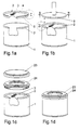
- a can 1 made of sheet metal with a Membrane film 2 are closed.
- the membrane film 2 can with a tear tab 3 connected in any way, for example by gluing be.
- the tab 3 can do this can be used, the introduced into the box 1 and connected to it at the edge Tear off membrane film 2 as a whole.
- This is cheaper because in the conventional design either a predetermined breaking point, e.g. by Punching, or a separation of the membrane film edge overlapping the can cutting edge created by the membrane foil plate spanning the can opening had to become.
- the membrane plate part spanning the can opening provides a certain stiffening mediated.
- the membrane film closing the can base preferably has 2 for stiffening (and also for achieving a slight radial Elasticity during deep drawing and / or sealing) preferably at least one circular bead.
- the membrane film 2 reinforced in this way can now form-fitting (so that the film shape does not when inserted into the can opening is changed), e.g. by means of a suction gripper known per se and be placed on the top of the can 1 in a first step.
- the raised edge is at least slightly conically divergent, i.e. it results in a vertical V, if only very small, but it does measurable angle ß, the size of less than 5 °, in particular less than 2 °.
- the diameter at the bottom of the membrane plate i.e. in the area of the cover surface 4 only a few tenths of a mm smaller than the opening diameter of the membrane plate , the height measured along the vertical V being only about 5 mm must be.
- the upper, larger diameter of the membrane film 2 becomes natural expediently chosen so that they are frictionally engaged when placed on by the suction pad is held at the top of the can 1.
- Another measure to secure the membrane sheet 2 on the top of the can 1 can in consist of a cross-section hook-shaped collar 6, which with the upper Edge of can 1 interacts.
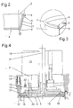
- the upper, mostly sharp-edged edge of the can Incidentally, 1 is preferably flanged to the outside (7 in Fig. 1a, 3) to a Prevent damage to the thin film or injury to the user.
- the stamp 8 is in accordance with FIG Fig.4 section shown. It consists of several parts, namely the actual stamp surface 9, which protrudes upwards from the pin 10 (only one is shown, preferably there are three) with the approach 11 of a stamp head 12 is connected. There is a centering ring 13 around the stamp surface 9 placed along guide pins 14 and against the effect at least a compression spring 15 is displaceable. Usually the ring takes 13 the left in Fig.4, lowered position, in which it is not, for example supported on the top of the stamp surface 9, if necessary but is also held by other means.
- the centering ring 13 takes up the edge of the can and has a recess 13 'for this purpose.
- the process can now proceed that the can 1 is on a lifting table and is lifted up, whereby the centering ring 13 against the action of the spring 15 in the one shown on the right top layer shifts.
- the stamp surface 9 emerges from the inside of the Ring 13 and thus presses the membrane film 2 in that shown in Fig.1b and 3 Location.
- the ring 13 could also be stationary and hold the can centered, while the stamp surface 9 is moved down.
- the approach 11 as a piston rod of a fluidic unit, preferably of a pneumatic piston-cylinder unit. It it goes without saying, however, that constructive considerations leave a lot of leeway is granted, since it is only on the relative movement of the parts shown and the Can arrives.
- the centering of the can or relative to it could also Membrane film 2 done in a variety of ways.
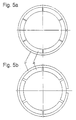
- the stamp 8 has a spreading device which in the embodiment of Figure 4 is formed by a wedge arrangement. Along a row of wedge segments 16 is guided at the top of the stamp surface 9, that they are radially outward with respect to the central axis A of the punch 8 can be moved.
- the back of the stamp surface could be used for guidance 9, for example, have grooves or slots (not shown). It however, the flat back of the stamp surface may also be sufficient for guidance.
- wedge segments 16 on themselves to press the hoisted Film edge area 5 of the membrane film 2 is used on the inner circumference of the can 1 , it is advantageous if they are made of elastic piston rings 17 or circlips can be spanned. This creates a more even one Circumferential surface when pressing these rings 17 against the film edge area 5 of the membrane film 2 and also results in a double function Restoring force that acts on the segments 16.
- a conical wedge 18 In order to press the wedge segments 16 radially outwards, there is a conical wedge 18 provided, preferably by means of an actuating rod 19 of a drive pneumatic type, downwards and between the wedge segments with their Wedge surfaces 20 can be moved.
- the reason for preferring one pneumatic drive is that there is a risk of contamination is hardly given by oil or leakage liquid and a maximum pressure is particularly easy can be set that does not expand the can. If the conical wedge 18 is moved down against the stamp surface 9, it spreads the Wedge segments 16 apart and thus presses the elastic rings 17 against the film edge area 5 outwards, where the can rim is stuck in the recess 13 '. To this The position of the membrane film 2 according to FIG. 1b is achieved.
- the membrane film 2 must also be secured and in general also be sealed. This can be done in a conventional manner Gluing, preferably done by means of heat sealing, because of the thin membrane film 2 yes the heat lets through relatively well.
- Gluing preferably done by means of heat sealing, because of the thin membrane film 2 yes the heat lets through relatively well.
- the outside the edge of the film may be coated with a hot glue 21 (FIG. 2).
- a heating device is then assigned to the spreading device 16-18. This could formed by heating coils accommodated in the wedge segments 16 be, but the space is very narrow at this point, and still movable Connections are to be provided. So although this possibility is not excluded may be a (e.g. annular) radiant heat source 22, e.g.
- wedge segments 16 and the rings 17 are provided which heat these parts, to heat the hot glue 21 (Fig.2) and with the inner wall of the Merge can 1.
- the wedge segments 16 can for example consist of one Ceramic material with good heat storage properties can be formed, which also improves wear properties.
- 5a shows the wedge segments 16 and a snap ring 17 in the closed, 5b (through the wedge pieces 18 of the not shown here, perpendicular to the plane of the drawing moving stamp 8) in the spread position for the purpose of heat sealing the membrane film 2 to the inner wall of the can.
- the wedge arrangement shown is only one possible, under certain circumstances preferred embodiment with regard to the life of the device is and that numerous modifications within the scope of the invention are conceivable.
- the tapered wedge 18 could be simply relative be formed to the stamp surface 9 movable pressure plate, wherein between a rubber bellows is provided on the top of the stamp surface 9 and this pressure plate may be.
- a horizontal drive, radially outwards, would also be suitable for the individual segments 16 conceivable, but structurally complex.
- the upper edge of the can may be heated represent the simpler solution from the outside for the purpose of heat sealing.
- a cover 23 or 24 (Fig.1c) can be applied will.
- a particular advantage of the present invention is that the Foils can be manufactured separately and if necessary kept in stock, where - with the same diameter of the cans 1 - cans with different Volume with the prefabricated and due to their training with the foil edge area 5 but sufficiently stable foils 2 can be loaded.
- This Film edge area 5 can also be easily coated with the adhesive 21, which is difficult to attach to the inner circumference of the can due to the risk of contamination would.
- the invention is of course not based on the use of an adhesive, as already explained.
- the output of the device according to the invention can be - e.g. on a rotary table arranged - multiple tools in a conventional manner be increased.
Landscapes
- Engineering & Computer Science (AREA)
- Mechanical Engineering (AREA)
- Closures For Containers (AREA)
- Rigid Containers With Two Or More Constituent Elements (AREA)
- Laminated Bodies (AREA)
- Making Paper Articles (AREA)
- Closing Of Containers (AREA)
- Wrappers (AREA)
- Electroplating Methods And Accessories (AREA)
- Separation Using Semi-Permeable Membranes (AREA)
- Lining Or Joining Of Plastics Or The Like (AREA)
Abstract
Description
Die Erfindung bezieht sich auf ein Verfahren und eine Vorrichtung zur
Herstellung einer Dose nach dem Oberbegriff des Anspruches 1, bzw. der
Ansprüche 7 und 8, sowie auf eine Halbfertigdose aus Metallblech mit einem
Membranfolienverschluss.The invention relates to a method and an apparatus for
Production of a can according to the preamble of
Metallblechdosen wurden bisher im wesentlichen entweder durch gemeinsames Verbördeln der Dosenschnittkante mit einem Blechdeckel verschlossen (z.B. nach WO 83/02577 oder US-A-3,952,677), oder mit einem mit Folie versehenen Blechring versehen (nach AT-A-368.919), oder die Innenseite der Dosenwand (1) musste - zumindest im Bereich des hochgezogenen Folienrandbereiches (5) - konisch ausgebildet werden (z.B. nach DE-U-94 14 440), was eine kompliziertere Dosenherstellung und hohe Toleranzen erforderte, damit beim Einfahren des Stempels immer dieselbe Lage des Membrantellers gegenüber der Dosenkante erzielt werden konnte.Tin cans have so far been essentially either joint crimping of the can cut edge with a metal lid sealed (e.g. according to WO 83/02577 or US-A-3,952,677), or with provided with a sheet metal ring provided with foil (according to AT-A-368.919), or the inside of the can wall (1) had to - at least in the area of the raised foil edge area (5) - be conical (e.g. according to DE-U-94 14 440), which is a more complicated can production and high Tolerances required so that when the stamp was retracted, it was always the same The position of the membrane plate in relation to the edge of the can could be achieved.
Andererseits sind die Schnittkante der Dose nicht übergreifende Teller mit hochgezogenem Rand für Dosen aus Kunststoff bekannt geworden (z.B. DE-A1-33 05 144 oder CH-A-629 984), doch handelte es sich dabei immer um relativ stabile Deckelteile für den Boden von druckbelastbaren Dosen oder solchen aus relativ weicher Wandung (z.B. nach US-A-4,599.123), die zum Versiegelungsvorgang eine äussere Druckaufnahmevorrichtung erforderten.On the other hand, the cut edge of the can is not overlapping plates raised edge for cans made of plastic (e.g. DE-A1-33 05 144 or CH-A-629 984), but this was always the case relatively stable lid parts for the bottom of pressure-resistant cans or those from relatively soft walls (e.g. according to US-A-4,599,123), which for Sealing process required an external pressure recording device.
Auch für Blechdosen wurden solche Teller schon vorgeschlagen (CH-A5-659633), doch funktioniert ihre Anbringung dort nur mit Hilfe eines wärmeleitenden (Blech-)Deckels, durch den zwecks Heissiegelung geheizt werden muss und der dann in der Dose verbleibt.Such plates have also been proposed for tin cans (CH-A5-659633), but their installation there only works with the help of a heat-conducting one (Sheet metal) cover, through which are heated for the purpose of heat sealing must and then remains in the can.
Nun ist in der WO-A-84/04507 bereits eine Vorrichtung beschrieben, bei der das Verschliessen einer Dose durch eine Membranfolie erfolgt, die mittels eines mechanisch nach aussen gedehnten Gummiringes an die Doseninnenwand gedrückt und mittels eines Heissklebers mit dieser verbunden wird. Dies erfordert jedoch eine sehr komplizierte Ausbildung des Gummiringes und des von aussen an die Dosenwand herangeführten Schweisswerkzeuges.WO-A-84/04507 has already described a device in which the sealing of a can is carried out by means of a membrane film a mechanically stretched rubber ring to the The inner wall of the can is pressed and with a hot glue is connected. However, this requires a very complicated training of the Rubber ring and that from the outside to the can wall Welding tool.
Die Erfindung hat sich nun die Aufgabe gestellt, ein Verfahren zur Herstellung
einer Blechdose, insbesondere einer solchen aus Weissblech oder
Aluminiumblech, mit einem einfachen und vor allem billigen Verschluss zu
schaffen. Dies gelingt erstmalig durch das im Kennzeichen des Anspruches 1
genannte Merkmal. Bevorzugte Weiterbildungen des erfindungsgemässen
Verfahrens sind in den Kennzeichen der Ansprüche 2 und 3 beschrieben.The object of the invention is now a process for the production
a tin can, especially one made of tinplate or
Aluminum sheet, with a simple and above all cheap closure too
create. This is achieved for the first time by the in the characterizing part of
Der Verschluss besteht dabei - wie in anderem Zusammenhang bekannt geworden - aus nur einer Membranfolie, gegebenenfalls aus (insbesondere mit dünner Aluminiumfolie kaschiertem) Papier und/oder Kunststoff, vorzugsweise jedoch einer Metallfolie, insbesondere aus Aluminium, alles im folgenden der Einfachheit halber auch nur als Membranfolie bezeichnet, und gestattet gegebenenfalls in an sich bekannter Weise, mit Hilfe von Aufreisslaschen die Dosenöffnung freizulegen. Der in Richtung der Dosenachse hochgezogene Rand des Membrantellers übergreift den - vorzugsweise umgebördelten - Dosenrand nicht, erleichtert damit das Aufreissen und belässt dem Dosenrand daher seine robuste Aussenseite bzw. Standfläche.The closure is there - as is known in another context become - from only one membrane film, possibly from (especially with thin aluminum foil laminated) paper and / or plastic, but preferably a metal foil, especially aluminum, all in following for the sake of simplicity also referred to as membrane film, and if necessary, in a manner known per se, with the aid of Tear tabs to expose the can opening. The towards the The edge of the membrane plate, which is pulled up, extends over the - preferably flanged - can edge does not make it easier Tear open and therefore leaves the edge of the can its robust outside or Footprint.
Die Membranfolie ist vorzugsweise höchstens 0.2 mm, insbesondere höchstens 0.1 mm stark, besteht z.B. aus einer 50µ Aluminiumfolie mit 20µ Heißsiegelbeschichtung auf der Innenseite und 10-20µ Gleitlackbeschichtung auf der Aussenseite und ist daher für den Verschluss der späteren Entnahmeöffnung geeignet. In Abhängigkeit vom Füllgut oder von einem eingesetzten Deckel kann jedoch bei Bedarf auch der Dosenboden erfindungsgemäss hergestellt werden. Weiters bevorzugt ist die Verwendung von geprägten Folien, weil diese sich leichter an Dosen mit wechselnder Toleranz anschmiegen lassen und auch bessere Stabilität ergeben.The membrane film is preferably at most 0.2 mm, in particular at most 0.1 mm thick, e.g. from a 50µ aluminum foil with 20µ Heat seal coating on the inside and 10-20µ anti-friction coating on the outside and is therefore for the closure of the later Removal opening suitable. Depending on the product or one However, the lid can also be used if necessary be produced according to the invention. Use is also preferred of embossed foils, because they are easier on cans with changing Let tolerance nestle and also result in better stability.
Im allgemeinen ist es bevorzugt, wenn die Membranfolie - zumindest in dem für die Verbindung mit der Innenwand der Dose bestimmten Bereich - mit einem Heißsiegellack beschichtet ist. Grundsätzlich kann aber auch die Innenwand der Dose in dem erwähnten Bereich - so wie diejenige von (z.B. mit Aluminiumfolie beschichteten) Kombidosen - mit einem Primer oder einer heißsiegelfähigen Schicht versehen sein; ansonsten erfordert die dichte Verbindung häufig den Einsatz spezieller insbesondere mehrkomponentiger - Klebstoffe oder Heißsiegellacke. Jedenfalls können damit auch blanke oder lackierte Blechdosen dichtend verschlossen werden.In general, it is preferred if the membrane film - at least in the area intended for connection to the inner wall of the box - with is coated with a heat seal lacquer. Basically, however Inner wall of the can in the area mentioned - such as that of (e.g. combination cans coated with aluminum foil - with a primer or a heat sealable layer; otherwise the density requires Connection often the use of special - especially multi-component - Adhesives or heat seal lacquers. In any case, it can also be bare or lacquered tin cans are sealed.
Bisher war es in umständlicher Weise erforderlich, gegen einen fixen, im Innern der (relativ weichen) Kartondose angebrachten Stempel durch das Zusammenfahren von Ringsegmenten oder das Zusammenfahren zweier Kegelflächen Druck von aussen gegen den stabilen Innenstempel auszuüben. Dies ist nunmehr beim erfindungsgemässen Verfahren nicht mehr der Fall. Die viel bessere und weniger umständliche Methode, den Druck von innen her aufzubringen, ist bei bisherigen, weichen Dosen nicht möglich, da für eine exakte, gegen den Innendruck gerichtete Aussenhalterung die Durchmessertoleranzen der Dose zu gross waren, oder es mussten Doseninnenrand und Stempel konisch ausgebildet werden. Bei dem erfindungsgemässen Verfahren nun ist überhaupt keine Aussenhalterung mehr erforderlich; es genügt eine lockere Zentrierung.So far, it has been cumbersome to have a fixed, in Inside the (relatively soft) cardboard box stamp by the Moving ring segments together or moving two together Apply conical surfaces from the outside against the stable inner punch. This is no longer the case with the method according to the invention. The much better and less cumbersome method of printing from the inside application is not possible with previous, soft cans, because for one exact, against the internal pressure directed outside bracket Diameter tolerances of the can were too large or had to The inner rim of the can and the stamp are conical. In which The method according to the invention is now no external mount at all more needed; a loose centering is sufficient.
Zur Durchführung des erfindungsgemässen Verfahrens eignet sich besonders
die Vorrichtung nach Anspruch 7 oder 8. Besondere Ausführungsformen sind
in den Kennzeichen der Ansprüche 9 und 10 beschrieben.The method according to the invention is particularly suitable
the device according to
Es versteht sich, dass die zum Verschliessen der erfindungsgemässen Dosen
dienenden Membranfolien zweckmässigerweise aus Material nach einem der
Ansprüche 4 bis 6 vorgefertigt sind, um dann mit Hilfe des
erfindungsgemässen Verfahrens auf die entsprechende Dosenöffnung
aufgebracht zu werden, damit sie auch in Dosen mit unterschiedlicher
Toleranz leicht eingebracht werden können und in der gewünschten Stellung
teilweise schon durch den konischen Folienrandbereich 5 aufliegen.It goes without saying that those used to close the cans according to the invention
serving membrane films expediently made of material according to one of the
Nun ist zwar - wie erwähnt - aus der CH-PS 659.633 eine Blechdose bekannt
geworden, deren Stirnseite mit einer hochgezogenen Membran verschlossen
ist. Allerdings ist dort erfindungswesentlich ein wärmeleitender Deckel
erforderlich, der in der Dose verbleibt, bis diese vom Letztverbraucher
geöffnet wird (Fig. 9), worauf aber auch die Membran entfernt wird und die
Dose nicht mehr dem Anspruch genügt. Die Halbfertigdose nach Anspruch 11
ist aber nun nur an einem Ende mit einer Membranfolie
verschlossen und dort frei von einem wärmeleitenden Deckel (wie dies in der
Branche üblich ist, und ist damit an der Gegenseite für das Befüllen geeignet,
also ein Zwischenprodukt, während das vergleichbare Zwischenprodukt nach
der CH-PS 659.633 einen solchen wärmeleitenden Deckel aufweist, der die
Dose verteuert und erschwert).Now - as mentioned - a tin can has become known from CH-PS 659.633, the end face of which is closed with a raised membrane. However, there is essential to the invention a heat-conducting lid that remains in the can until it is opened by the last consumer (FIG. 9), whereupon the membrane is also removed and the can no longer meets the requirements. The semi-finished can according to
Ein parallel zum Membranteller verlaufender, breiter Kragen, wie er z.B. in der US-A-4,599.123 beschrieben ist, hat sich als ausserordentlich ungünstig erwiesen, da er beim Einziehen in die Dose - ohne den Schnittrand der Dosenkante zu übergreifen - dazu führen muss, dass sich Falten bilden, die eine dichte Verbindung der Folie mit der Doseninnenwand erschweren oder sogar verunmöglichen.A wide collar running parallel to the diaphragm plate, e.g. in the US-A-4,599,123 has been found to be extremely unfavorable proven that when it is pulled into the can - without the cut edge of the Reaching over the edge of the can - must lead to wrinkles forming difficult a tight connection of the film with the inner wall of the can or even make it impossible.
Zur endgültigen Anbringung sind natürlich zahlreiche Möglichkeiten nach dem Stand der Technik gegeben. Da aber die erfindungsgemäss verwendete Folie relativ dünn und bevorzugt eine Folie mit gutem Wärmeleitvermögen ist, wird man von einem Warmverbindungsverfahren Gebrauch machen, etwa einen Heisskleber an der Aussenseite auftragen.There are, of course, numerous possibilities for the final attachment after the State of the art. But since the film used according to the invention is relatively thin and preferably a film with good thermal conductivity to use a hot joining process, such as one Apply hot glue to the outside.
Weitere Einzelheiten der Erfindung ergeben sich an Hand der nachfolgenden Beschreibung von in der Zeichnung erläuterten Ausführungsbeispielen. Es zeigen:
- Fig. 1
- den Ablauf des erfindungsgemässen Verfahrens;
Fig.2und 3- vergrösserte Details II und III aus der Fig.1a bzw. 1b;
- Fig.4
- einen Schnitt durch die erfindungsgemässe Vorrichtung;
- Fig. 5a und b
- einen horizontalen Teilschnitt durch die erfindungsgemässe Vorrichtung in zwei verschiedenen Arbeitspositionen.
- Fig. 1
- the sequence of the method according to the invention;
- Fig. 2 and 3
- enlarged details II and III from FIGS. 1a and 1b;
- Fig. 4
- a section through the inventive device;
- 5a and b
- a partial horizontal section through the inventive device in two different working positions.
Gemäss der Darstellung a) in Fig.1 soll eine Dose 1 aus Metallblech mit einer
Membranfolie 2 verschlossen werden. Die Membranfolie 2 kann mit einer Aufreisslasche
3 in an sich beliebiger Weise, beispielsweise durch Klebung, verbunden
sein. Im Gegensatz zu herkömmlichen Aufreisslaschen kann die Lasche 3 dazu
benutzt werden, die in die Dose 1 eingebrachte und am Rande mit ihr verbundene
Membranfolie 2 als Ganzes abzureissen. Dies ist deswegen günstiger, weil
bei der herkömmlichen Ausführung entweder eine Sollbruchstelle, z.B. durch
Stanzen, oder eine Trennung des die Dosenschnittkante übergreifenden Membranfolienrandes
vom die Dosenöffnung überspannenden Membranfolienteller geschaffen
werden musste. Bei einer dünnen Folie von vorzugsweise maximal 0.2
mm, im allgemeinen sogar von höchstens 0.1 mm, bedeutete dies immer noch
Schwierigkeiten.According to the representation a) in Figure 1, a
Es versteht sich, dass eine derart dünne Folie, die ja nur der Frischhaltung oder
der Aromabewahrung bzw. zur Verhinderung einer Kontaminierung dient, relativ
schwer zu handhaben ist. Erfindungsgemäss besitzt sie nun am Umfang eines
Abdeckbereiches 4 einen rundum hochgezogenen Folienrandbereich 5, der dem
die Dosenöffnung überspannenden Membrantellerteil eine gewisse Versteifung
vermittelt. Vorzugsweise weist die den Dosenboden verschliessende Membranfolie
2 zwecks Versteifung (und auch zwecks Erzielung einer geringfügigen, radialen
Elastizität beim Tiefziehen und/oder Einsiegeln) vorzugsweise wenigstens eine
kreisringförmige Sicke auf. Die solcherart verstärkte Membranfolie 2 kann nun
formschlüssig (damit die Folienform beim Einsetzen in die Dosenöffnung nicht
verändert wird), z.B. mittels eines an sich bekannten Sauggreifers aufgenommen
und in einem ersten Schritt auf die Oberseite der Dose 1 aufgesetzt werden. Hier
ergibt sich eine weitere, mit einer dünnen Folie verbundene Schwierigkeit: Es
muss nämlich gesichert werden, dass die Folie an der Oberseite der Dose 1 verbleibt,
so dass sie im nächsten Schritt mit der Doseninnenwand dicht verbunden
werden kann. An sich wäre es denkbar, den oberen Rand der Dose 1 mit einem
Klebemittel derart zu versehen, dass die Folie daran in der gewünschten Lage
hängen bleibt. Vorteilhaft geschieht dies jedoch nach der Erfindung in einer
Weise, wie sie aus der Fig.2 besser ersichtlich ist. It goes without saying that such a thin film, which is only used for keeping fresh or
to preserve the aroma or to prevent contamination, relatively
is difficult to handle. According to the invention, it now has one
Demnach ist der hochgezogene Rand mindestens leicht konisch divergierend,
d.h. es ergibt sich zur Vertikalen V ein, wenn auch nur sehr kleiner, aber doch
messbarer Winkel ß, der eine Grösse von weniger als 5°, insbesondere weniger
als 2° haben wird. In einem praktischen Ausführungsbeispiel wird der Durchmesser
an der Unterseite des Membrantellers, d.h. im Bereich der Abdeckfläche
4 nur um wenige Zehntel mm kleiner als der Öffnungsdurchmesser des Membrantellers
sein, wobei die entlang der Vertikalen V gemessene Höhe nur etwa 5
mm betragen muss.Accordingly, the raised edge is at least slightly conically divergent,
i.e. it results in a vertical V, if only very small, but it does
measurable angle ß, the size of less than 5 °, in particular less
than 2 °. In a practical embodiment, the diameter
at the bottom of the membrane plate, i.e. in the area of the
Dabei wird der obere, grössere Durchmesser der Membranfolie 2 natürlich
zweckmässig so gewählt, dass sie beim Aufsetzen durch den Sauggreifer reibungsschlüssig
an der Oberseite der Dose 1 gehalten wird. Eine weitere Massnahme
zur Sicherung der Membranfolie 2 an der Oberseite der Dose 1 kann in
einem im Querschnitt hakenförmigen Kragen 6 bestehen, der mit dem oberen
Rand der Dose 1 zusammenwirkt. Der obere, meist scharfkantige Rand der Dose
1 ist übrigens vorzugsweise nach aussen umgebördelt (7 in Fig. 1a, 3), um eine
Beschädigung der dünnen Folie oder eine Verletzung des Benutzers hintanzuhalten.The upper, larger diameter of the
Die Membranfolie 2 sitzt also mit diesem Kragen 6 am Rande der Dose fest. Dies
ist allerdings nur ein Zwischenschritt beim Schliessen der Dose 1, der die anschliessenden
Schritte nicht behindern soll. Dazu gehört die Einwirkung eines, in
Fig. 1b lediglich schematisch gezeigten Stempels 8, der die Membranfolie 2 in die
aus Fig. 1b ersichtliche Stellung drückt. Dabei gleitet der Kragen 6 aus der in
Fig .3 strichpunktiert angedeuteten Lage, in der er sich vor dem Niederdrücken
des Stempels 8 befand, in das Innere der Dose und legt sich auf Grund der Duktilität
des Folienmateriales (bei gleichzeitig gegebener ausreichender Zähfestigkeit)
in der in Fig.3 mit vollen Linien wiedergegebenen Lage an den Innenumfang
der Dose 1 an. Dabei geht auch die an Hand der Fig .2 veranschaulichte Konizität
des Folienrandbereiches 5 mit dem kleinen Winkel ß in eine Zylinderform über, so
dass sich der Folienrandbereich 5 eng an den Dosenumfang legt. Durch die geringe
Konizität wird die Bildung von Falten und Runzeln - wie in US-A-4,599.123
ausdrücklich erwähnt - vermieden.The
Das erfindungsgemässe Verfahren und die erfindungsgemässe Vorrichtung bewirken,
wie im folgenden beschrieben, die dichte Verbindung der Membranfolie 2
mit dem zylindrischen Bereich der Doseninnenwand unmittelbar unter dem
(vorzugsweise gebördelten) Dosenrand:The method according to the invention and the device according to the invention bring about
as described below, the tight connection of the
Der Stempel 8 ist gemäss einer bevorzugten Ausführung entsprechend dem in
Fig.4 gezeigten Schnitt ausgebildet. Er besteht aus mehreren Teilen, nämlich der
eigentlichen Stempelfläche 9, die über nach oben vorragende Zapfen 10 (nur einer
ist gezeigt, vorzugsweise sind es drei) mit dem Ansatz 11 eines Stempelkopfes
12 verbunden ist. Rund um die Stempelfläche 9 ist ein Zentrierring 13
gelegt, der entlang von Führungsstiften 14 und entgegen der Wirkung mindestens
einer Druckfeder 15 verschiebbar ist. Normalerweise nimmt der Ring 13
die in Fig.4 linke, abgesenkte Stellung ein, in der er sich beispielsweise in nicht
gezeigter Weise an der Oberseite der Stempelfläche 9 abstützt, gegebenenfalls
aber auch durch andere Mittel gehalten ist.According to a preferred embodiment, the
In dieser Stellung nimmt der Zentrierring 13 den Dosenrand auf und besitzt zu
diesem Zwecke eine Ausnehmung 13'. Es kann nun der Vorgang so ablaufen,
dass die Dose 1 auf einem Hebetisch steht und hochgehoben wird, wodurch sich
der Zentrierring 13 entgegen der Wirkung der Feder 15 in die rechts gezeigte
obere Lage verschiebt. Gleichzeitig tritt die Stempelfläche 9 aus dem Inneren des
Ringes 13 hervor und presst so die Membranfolie 2 in die in Fig.1b und 3 gezeigte
Lage.In this position, the centering
Alternativ könnte der Ring 13 auch ortsfest sein und die Dose zentriert festhalten,
während die Stempelfläche 9 abwärts bewegt wird. In diesem Fall wäre beispielsweise
der Ansatz 11 als Kolbenstange eines fluidischen Aggregates, vorzugsweise
eines pneumatischen Kolben-Zylinder-Aggregates, auszubilden. Es
versteht sich aber, dass hier konstruktiven Überlegungen ein weiter Spielraum
eingeräumt ist, da es ja nur auf die Relativbewegung der gezeigten Teile und der
Dose ankommt. Auch könnte die Zentrierung der Dose bzw. relativ zu ihr der
Membranfolie 2 auf die verschiedenste Weise erfolgen.Alternatively, the
Aus den vorherigen Erläuterungen ist es klar, dass es wichtig ist, den hochgezogenen
Folienrandbereich 5 der Membranfolie 2 möglichst eng an den Innenumfang
der Dose zu legen (wie dies in Fig.3 gezeigt ist), um ihn mit diesem fest zu
verbinden. Zu diesem Zweck weist der Stempel 8 eine Spreizvorrichtung auf, die
im Ausführungsbeispiel nach Fig.4 von einer Keilanordnung gebildet ist. Entlang
der Oberseite der Stempelfläche 9 ist eine Reihe von Keilsegmenten 16 so geführt,
dass sie bezüglich der zentralen Achse A des Stempels 8 radial nach aussen
verschoben werden können. Zur Führung könnte die Rückseite der Stempelfläche
9 beispielsweise (nicht dargestellte) Nuten oder Schlitze aufweisen. Es
mag allerdings auch die flache Rückseite der Stempelfläche zur Führung ausreichen.From the previous explanations, it is clear that it is important to pull up
Obwohl die Keilsegmente 16 an sich selbst zum Anpressen des hochgezogenen
Folienrandbereiches 5 der Membranfolie 2 an den Innenumfang der Dose 1 herangezogen
werden könnten, ist es vorteilhaft, wenn sie von elastischen Kolbenringen
17 oder Seegerringen umspannt werden. Dies schafft eine gleichmässigere
Umfangsfläche beim Andrücken dieser Ringe 17 gegen den Folienrandbereich
5 der Membranfolie 2 und ergibt überdies in einer Doppelfunktion auch noch eine
Rückstellkraft, die auf die Segmente 16 wirkt.Although the
Um die Keilsegmente 16 radial nach aussen zu drücken, ist ein konischer Keil 18
vorgesehen, der mittels einer Betätigungsstange 19 von einem Antrieb, vorzugsweise
pneumatischer Art, abwärts und zwischen die Keilsegmente mit ihren
Keilflächen 20 bewegt werden kann. Der Grund für die Bevorzugung eines
pneumatischen Antriebes liegt darin, dass dabei eine Verschmutzungsgefahr
durch Öl oder Leckflüssigkeit kaum gegeben ist und besonders einfach ein Maximaldruck
eingestellt werden kann, der die Dose nicht aufweitet. Wenn nun der
konische Keil 18 abwärts gegen die Stempelfläche 9 bewegt wird, spreizt er die
Keilsegmente 16 auseinander und drückt damit die elastischen Ringe 17 gegen
den Folienrandbereich 5
nach aussen, wo der Dosenrand in der Ausnehmung 13' festsitzt. Auf diese
Weise wird die Stellung der Membranfolie 2 nach Fig. 1b erreicht.In order to press the
In dieser Lage muss nun aber die Membranfolie 2 auch gesichert und im allgemeinen
auch abgedichtet werden. Dies kann auf herkömmliche Weise mittels
Klebung, bevorzugt mittels Heißsiegelung geschehen, weil die dünne Membranfolie
2 ja die Wärme relativ gut hindurchlässt. Zu diesem Zweck kann die Aussenseite
des Folienrandes mit einem Heisskleber 21 beschichtet sein (Fig.2). Der
Spreizvorrichtung 16-18 ist dann eine Heizeinrichtung zugeordnet. Diese könnte
an sich von in den Keilsegmenten 16 untergebrachten Heizwicklungen gebildet
sein, doch ist der Platz an dieser Stelle sehr eng, wobei auch noch bewegliche
Anschlüsse vorzusehen sind. Obwohl also diese Möglichkeit nicht ausgeschlossen
sein soll, mag eine (z.B. ringförmige) Strahlungsheizquelle 22, z.B. oberhalb
der Keilsegmente 16 und der Ringe 17 vorgesehen werden, die diese Teile aufheizt,
um den Heisskleber 21 (Fig.2) zu erwärmen und mit der Innenwand der
Dose 1 zu verschmelzen. Die Keilsegmente 16 können beispielsweise aus einem
Keramikmaterial mit guten Wärmespeichereigenschaften gebildet sein, was auch
die Abnützungseigenschaften verbessert.In this position, however, the
Fig. 5a zeigt die Keilsegmente 16 und einen Sprengring 17 in geschlossener, Fig.
5b (durch die Keilstücke 18 des hier nicht dargestellten, senkrecht zur Zeichnungsebene
bewegten Stempels 8) in gespreizter Stellung zwecks Heißsiegelung
der Membranfolie 2 an die Doseninnenwand.5a shows the
Es versteht sich, dass die gezeigte Keilanordnung nur ein mögliches, unter Umständen
im Hinblick auf die Lebensdauer der Vorrichtung bevorzugtes, Ausführungsbeispiel
ist, und dass im Rahmen der Erfindung zahlreiche Abwandlungen
denkbar sind. Beispielsweise könnte der konische Keil 18 einfach durch eine relativ
zur Stempelfläche 9 bewegliche Druckplatte gebildet sein, wobei zwischen
der Oberseite der Stempelfläche 9 und dieser Druckplatte ein Gummibalg vorgesehen
sein mag. Dieser dehnt sich bei Beaufschlagung mit einem Druckmedium
durch die an Stelle des Teiles 18 eingesetzte Druckplatte, die dann ebenfalls mit
der Stange 19 zu ihrer Betätigung verbunden wäre, von oben nach der Seite hin
aus und drückt somit auf die verschiebbaren Teile 16 oder unmittelbar auf die
Ringe 17. Auch ein horizontal verlaufender Antrieb, radial nach aussen, wäre für
die einzelnen Segmente 16 denkbar, aber konstruktiv aufwendig. Besonders in
diesem Fall, aber auch in anderen Fällen mag eine Beheizung des oberen Dosenrandes
von aussen zwecks Heißsiegelung die einfachere Lösung darstellen.It is understood that the wedge arrangement shown is only one possible, under certain circumstances
preferred embodiment with regard to the life of the device
is and that numerous modifications within the scope of the invention
are conceivable. For example, the tapered
Sobald die Dose 1 in der Lage nach Fig. 1b verschlossen ist, sind gegebenenfalls
weitere, zusätzliche Massnahmen von Vorteil. Um etwa die verletzliche Membranfolie
2 zu schützen, kann noch ein Deckel 23 oder 24 (Fig.1c) aufgebracht
werden.As soon as the
Ein besonderer Vorteil der vorliegenden Erfindung besteht auch darin, dass die
Folien separat gefertigt und gegebenenfalls auf Lager gehalten werden können,
wobei - bei gleichem Durchmesser der Dosen 1 - Dosen mit unterschiedlichem
Volumen mit den vorgefertigten und auf Grund ihrer Ausbildung mit dem Folienrandbereich
5 doch ausreichend stabilen Folien 2 bestückt werden können. Dieser
Folienrandbereich 5 lässt sich auch leicht mit dem Klebstoff 21 beschichten,
der am Innenumfang der Dose wegen der Verschmutzungsgefahr schlecht anzubringen
wäre. Anderseits ist die Erfindung natürlich nicht auf die Verwendung
eines Klebstoffes beschränkt, wie bereits erläutert wurde.A particular advantage of the present invention is that the
Foils can be manufactured separately and if necessary kept in stock,
where - with the same diameter of the cans 1 - cans with different
Volume with the prefabricated and due to their training with the
Die Erfindung ist auf die dargestellten Ausführungsformen nicht eingeschränkt. So kann die Ausstossleistung der erfindungsgemässen Vorrichtung mit - z.B. auf einem Drehtisch angeordneten - Mehrfachwerkzeugen in an sich bekannter Weise gesteigert werden.The invention is not restricted to the illustrated embodiments. So the output of the device according to the invention can be - e.g. on a rotary table arranged - multiple tools in a conventional manner be increased.
Claims (12)
- Process for manufacturing a tin can with a paper, plastic or metal foil membrane (2) which is provided on at least one end face and is inserted into the can with raised foil edge region (5) and which closes at least one end face so that the outside of the foil edge region (5) raised in the direction of the can axis (A) is tightly connected, preferably adhesively bonded or heat-sealed, to the inside of the can wall (1), which inside is essentially cylindrical at least in the raised foil edge region (5), characterized in that the foil membrane (2) is pressed by means of a stamp (8) having a spreadable (17) circumference against the inner surface of the can (1), the spreading being effected without being opposed by a force from a pressure-absorbing device, and the tight connection between the raised foil edge region (5) - essentially over its total vertical dimension - and the inner surface of the can (1) then being produced under the action of heat.
- Process according to Claim 1, characterized in that the spreading of the stamp circumference is effected by a translation of the axial movement of a stamp (3) into a radial movement of pressure elements, in particular of wedge segments (16) and/or spring rings and/or piston rings (17).
- Process according to Claim 1, characterized in that the spreading of the stamp circumference is effected by a pneumatically operated rubber bellows.
- Process according to any of the preceding Claims, characterized in that the foil (2) used has, on its radially outer surface, a foil edge region (5) which is raised - preferably diverging conically upwards by 0.2 to 0.3 mm - and which preferably has an adhesive coat (21), in particular comprising a hotmelt adhesive, on its outer surface.
- Process according to any of the preceding Claims, characterized in that the foil (2) used has, at the free end of the foil edge region (5), a collar (6) which points radially outwards and is approximately hook-shaped in cross-section.
- Process according to any of the preceding Claims, characterized in that the foil (2) is embossed or grained.
- Apparatus for carrying out the process according to any of the preceding Claims, having a displaceably mounted stamp (8) with a circumference spreadable transversely to the displacement direction, the displacement means (19) for the stamp and a spreading means (16, 18) for producing the corresponding movements being provided, characterized in that the stamp (8) is displaceably mounted inside a centring means (13) for the foil membrane (2) and the can (1), and a heating means (22) for the circumference of the stamp (8) or for the upper can edge is provided from the outside.
- Apparatus for carrying out the process according to any of Claims 1 to 6, having a displaceably mounted stamp (8) with a circumference spreadable transversely to the displacement direction, a displacement means (19) for the stamp and a spreading means (16, 18) for producing the corresponding movements being provided, characterized in that a centring means (13) for the foil membrane (2) and the can (1) and a heating means (22) for the circumference of the stamp (8) are provided.
- Apparatus according to Claim 7 or 8, characterized in that the spreading means (16, 18) comprises a combination of, on the one hand, at least two, preferably three or four, radially expandable piston rings or spring rings (16) with openings offset relative to one another and, on the other hand, at least three, preferably four to eight, in particular six, wedges (18, 20) arranged in the form of a ring.
- Apparatus according to any of Claims 7 to 9, characterized in that the spreading means consists of a hydraulically or pneumatically operable rubber bellows arranged along the stamp circumference.
- Semifinished can comprising a sheet metal cylinder which is open at one end face for filling but is closed at the other end face by a foil membrane (2) comprising paper, plastic film or metal foil in such a way that the outside of the foil edge region (5) raised in the direction of the can axis (A) is tightly connected, preferably adhesively bonded or heat-sealed, to the inside of the can wall (1) without overlapping the edge of the can wall, characterized in that the inside of the can wall (1) is cylindrical - at least in the raised foil edge region (5) - and the foil edge region (5) is free of a heat-conducting cover.
- Can according to Claim 11, characterized in that the edge (7) of the can wall is flanged in an outward direction and/or the foil edge region (5) rests against the inner surface of the can (1) essentially without folds and creases.
Applications Claiming Priority (3)
| Application Number | Priority Date | Filing Date | Title |
|---|---|---|---|
| EP95104906 | 1995-04-02 | ||
| DE95104906 | 1995-04-02 | ||
| PCT/EP1996/001410 WO1996031406A1 (en) | 1995-04-02 | 1996-03-30 | Tin can with a foil closure membrane, and a process, device and foil for manufacturing the can |
Publications (2)
| Publication Number | Publication Date |
|---|---|
| EP0819086A1 EP0819086A1 (en) | 1998-01-21 |
| EP0819086B1 true EP0819086B1 (en) | 1998-12-23 |
Family
ID=8219151
Family Applications (1)
| Application Number | Title | Priority Date | Filing Date |
|---|---|---|---|
| EP96910945A Expired - Lifetime EP0819086B1 (en) | 1995-04-02 | 1996-03-30 | Process and device for manufacturing a tin can with a foil closure membrane, and semifinished can with a foil closure membrane |
Country Status (15)
| Country | Link |
|---|---|
| EP (1) | EP0819086B1 (en) |
| JP (1) | JP3689115B2 (en) |
| KR (2) | KR20050038655A (en) |
| CN (1) | CN1063401C (en) |
| AT (1) | ATE174859T1 (en) |
| AU (1) | AU694023B2 (en) |
| BR (1) | BR9604869A (en) |
| CA (1) | CA2217311C (en) |
| DE (1) | DE59601055D1 (en) |
| DK (1) | DK0819086T3 (en) |
| ES (1) | ES2127634T3 (en) |
| GR (1) | GR3029457T3 (en) |
| NZ (1) | NZ305862A (en) |
| WO (1) | WO1996031406A1 (en) |
| ZA (1) | ZA962628B (en) |
Cited By (1)
| Publication number | Priority date | Publication date | Assignee | Title |
|---|---|---|---|---|
| DE202008005479U1 (en) | 2008-04-18 | 2008-08-21 | Gebrüder Leonhardt GmbH & Co. KG Blema Kircheis | Container with closure element and device for its production |
Families Citing this family (15)
| Publication number | Priority date | Publication date | Assignee | Title |
|---|---|---|---|---|
| ATE205155T1 (en) * | 1997-05-14 | 2001-09-15 | Werner Grabher | CAN WITH A CLOSURE MEMBRANE AND A HINGED LID |
| FI120485B (en) * | 1998-05-29 | 2009-11-13 | Lamican Oy | Device for forming a package |
| FI981219A7 (en) | 1998-05-29 | 1999-11-30 | Upm Kymmene Corp | Method and packaging machine for forming a filled package, a blank material web and a filled package |
| EP1855822B1 (en) | 2005-03-01 | 2009-12-30 | CROWN Packaging Technology, Inc. | Packaging can |
| EP1762503A1 (en) * | 2005-09-07 | 2007-03-14 | Alcan Technology & Management Ltd. | Sterilizable semi-rigid container with lid and label |
| US7703625B2 (en) | 2006-11-15 | 2010-04-27 | Sonoco Development, Inc. | Container lid formed as a laminate having a built-in opening feature, container incorporating same, and method for making same |
| DE102010008838A1 (en) * | 2010-02-22 | 2011-08-25 | RHODIUS Schleifwerkzeuge GmbH & Co. KG, 56659 | Packaging for resin-bonded grinding wheels |
| WO2013107899A1 (en) * | 2012-01-20 | 2013-07-25 | Ardagh Mp Group Netherlands B.V. | Cover unit with adapter, cover, and sealing film for a container |
| BR112018000948A2 (en) * | 2015-07-24 | 2018-09-04 | Ardagh Mp Group Netherlands B.V. | process, tool and arrangement for airtight closure of a container as well as airtight container |
| CN106424426B (en) * | 2016-12-07 | 2018-01-23 | 贵州黎阳航空动力有限公司 | A kind of double wall steep-taper inner cone closing device |
| DE102017101150B3 (en) | 2017-01-20 | 2018-05-30 | Ardagh Mp Group Netherlands B.V. | Tool and method for closing a container and method for producing a container having a plurality of spaces |
| US11091304B2 (en) | 2018-01-02 | 2021-08-17 | Owens-Brockway Glass Container Inc. | Container closure with vacuum-indicating pull tab |
| CH716830A1 (en) * | 2019-11-22 | 2021-05-31 | Soudronic Ag | Methods and devices for the production of tear-off lids. |
| SE543911C2 (en) | 2020-01-14 | 2021-09-21 | A & R Carton Lund Ab | An expansible press plunger, an attachment unit for attaching a container element in a container body and a method for attaching a container element in a container body |
| SE544726C2 (en) * | 2020-10-20 | 2022-10-25 | Ar Packaging Systems Ab | An expansible press plunger, an attachment unit for attaching a container element to a container body and a method for sealing a packaging container |
Family Cites Families (5)
| Publication number | Priority date | Publication date | Assignee | Title |
|---|---|---|---|---|
| JPS58109923U (en) * | 1982-01-22 | 1983-07-27 | 本州製紙株式会社 | Easy-open lid for cylindrical containers |
| US4599123A (en) * | 1982-09-02 | 1986-07-08 | Esselte Pac Aktiebolag | Method and apparatus for manufacturing a container having an inner end closure |
| CH659633A5 (en) * | 1983-05-05 | 1987-02-13 | Hoffmann Ag Geb | Ready-to-install sealing unit for a container, a method for mounting a sealing unit on a container body and a container |
| SE454433B (en) * | 1983-05-19 | 1988-05-02 | Esseltepack Ab | DEVICE FOR SHAPING AND INSTALLATION OF INTERNAL LOCK IN PACKAGING |
| DE9414440U1 (en) * | 1994-09-06 | 1994-12-01 | Nestlé Deutschland AG, 60528 Frankfurt | Tin can with foil closure |
-
1996
- 1996-03-30 EP EP96910945A patent/EP0819086B1/en not_active Expired - Lifetime
- 1996-03-30 ES ES96910945T patent/ES2127634T3/en not_active Expired - Lifetime
- 1996-03-30 KR KR1020057005324A patent/KR20050038655A/en not_active Ceased
- 1996-03-30 DE DE59601055T patent/DE59601055D1/en not_active Expired - Fee Related
- 1996-03-30 AU AU53987/96A patent/AU694023B2/en not_active Ceased
- 1996-03-30 CA CA002217311A patent/CA2217311C/en not_active Expired - Fee Related
- 1996-03-30 NZ NZ305862A patent/NZ305862A/en not_active IP Right Cessation
- 1996-03-30 BR BR9604869-7A patent/BR9604869A/en not_active IP Right Cessation
- 1996-03-30 AT AT96910945T patent/ATE174859T1/en not_active IP Right Cessation
- 1996-03-30 DK DK96910945T patent/DK0819086T3/en active
- 1996-03-30 JP JP52996796A patent/JP3689115B2/en not_active Expired - Fee Related
- 1996-03-30 WO PCT/EP1996/001410 patent/WO1996031406A1/en not_active Ceased
- 1996-03-30 KR KR1019970706908A patent/KR100526838B1/en not_active Expired - Fee Related
- 1996-03-30 CN CN96194081A patent/CN1063401C/en not_active Expired - Fee Related
- 1996-04-02 ZA ZA962628A patent/ZA962628B/en unknown
-
1999
- 1999-02-19 GR GR990400542T patent/GR3029457T3/en unknown
Cited By (1)
| Publication number | Priority date | Publication date | Assignee | Title |
|---|---|---|---|---|
| DE202008005479U1 (en) | 2008-04-18 | 2008-08-21 | Gebrüder Leonhardt GmbH & Co. KG Blema Kircheis | Container with closure element and device for its production |
Also Published As
| Publication number | Publication date |
|---|---|
| ATE174859T1 (en) | 1999-01-15 |
| ES2127634T3 (en) | 1999-04-16 |
| JP3689115B2 (en) | 2005-08-31 |
| GR3029457T3 (en) | 1999-05-28 |
| WO1996031406A1 (en) | 1996-10-10 |
| KR100526838B1 (en) | 2006-06-21 |
| CN1185138A (en) | 1998-06-17 |
| JPH11509810A (en) | 1999-08-31 |
| BR9604869A (en) | 1999-11-30 |
| KR19980703504A (en) | 1998-11-05 |
| CA2217311A1 (en) | 1996-10-10 |
| EP0819086A1 (en) | 1998-01-21 |
| ZA962628B (en) | 1996-10-07 |
| KR20050038655A (en) | 2005-04-27 |
| CA2217311C (en) | 1999-05-25 |
| DE59601055D1 (en) | 1999-02-04 |
| AU694023B2 (en) | 1998-07-09 |
| AU5398796A (en) | 1996-10-23 |
| DK0819086T3 (en) | 1999-08-23 |
| CN1063401C (en) | 2001-03-21 |
| NZ305862A (en) | 1999-10-28 |
Similar Documents
| Publication | Publication Date | Title |
|---|---|---|
| EP0819086B1 (en) | Process and device for manufacturing a tin can with a foil closure membrane, and semifinished can with a foil closure membrane | |
| DE69508986T2 (en) | Process for the production of a hose pack and pack produced by this process | |
| DE69504749T2 (en) | Container with closure | |
| DE3935201C2 (en) | ||
| DE69006124T2 (en) | Method and device for producing a ring for a container closure. | |
| DE69813548T2 (en) | CONTAINER CLOSURE | |
| DE102008014758A1 (en) | Closed portion package for soluble coffee substance for espresso machine, has side wall provided with carrier section, and inner section, which is formed of flexible plastic foil deformable under pressure and laminated on carrier section | |
| DE2510967A1 (en) | CONTAINER | |
| EP3571122A2 (en) | Tool and method for closing a container and method for producing a container with several compartments | |
| DE3008274C2 (en) | Can closure | |
| DE102008031812A1 (en) | Device for pressing two or multiple layers of cup or made of plastic and paper material, particularly from inner cover, has outer cover of insulating cup and two radially expanding die stocks | |
| EP0007487A1 (en) | Sealed can and preformed closure element therefor, as well as method and apparatuses for manufacturing them | |
| DE3923772A1 (en) | EASY TO OPEN LID FOR BEVERAGE CAN | |
| EP2804706B1 (en) | Method for producing a can with a ring pull top, and can with a ring pull top | |
| EP3360676B1 (en) | Container and device and method for forming a container made from paper or paper-like material | |
| DE2630022A1 (en) | CONTAINERS, SUCH AS CUPS OR BOTTLES, MADE OF THERMOPLASTIC MATERIAL AND METHOD FOR ITS MANUFACTURING | |
| DE2042937A1 (en) | Packaging container | |
| DE10055527C2 (en) | can end | |
| DE4332306A1 (en) | Method for the production of an easy-to-open can lid from sheet metal | |
| EP0639509B1 (en) | Deep drawn lid made of paper, and process for making same | |
| DE69635381T2 (en) | Sealed mounting plate for aerosol container | |
| DE3875063T2 (en) | METHOD AND DEVICE FOR ATTACHING END PLATES TO PACKAGING. | |
| WO2017017588A2 (en) | Method, tool and assembly for tightly closing a receptacle, and tightly closed receptacle | |
| EP1819501B1 (en) | Sealing machine and method | |
| DE1604457C3 (en) | Method and device for producing a bottom edge bead on deep-drawn cups |
Legal Events
| Date | Code | Title | Description |
|---|---|---|---|
| PUAI | Public reference made under article 153(3) epc to a published international application that has entered the european phase |
Free format text: ORIGINAL CODE: 0009012 |
|
| 17P | Request for examination filed |
Effective date: 19970927 |
|
| AK | Designated contracting states |
Kind code of ref document: A1 Designated state(s): AT BE CH DE DK ES FR GB GR IE IT LI NL PT SE |
|
| GRAG | Despatch of communication of intention to grant |
Free format text: ORIGINAL CODE: EPIDOS AGRA |
|
| 17Q | First examination report despatched |
Effective date: 19980210 |
|
| GRAG | Despatch of communication of intention to grant |
Free format text: ORIGINAL CODE: EPIDOS AGRA |
|
| GRAH | Despatch of communication of intention to grant a patent |
Free format text: ORIGINAL CODE: EPIDOS IGRA |
|
| GRAG | Despatch of communication of intention to grant |
Free format text: ORIGINAL CODE: EPIDOS AGRA |
|
| GRAH | Despatch of communication of intention to grant a patent |
Free format text: ORIGINAL CODE: EPIDOS IGRA |
|
| GRAH | Despatch of communication of intention to grant a patent |
Free format text: ORIGINAL CODE: EPIDOS IGRA |
|
| GRAA | (expected) grant |
Free format text: ORIGINAL CODE: 0009210 |
|
| AK | Designated contracting states |
Kind code of ref document: B1 Designated state(s): AT BE CH DE DK ES FR GB GR IE IT LI NL PT SE |
|
| REF | Corresponds to: |
Ref document number: 174859 Country of ref document: AT Date of ref document: 19990115 Kind code of ref document: T |
|
| REG | Reference to a national code |
Ref country code: CH Ref legal event code: EP |
|
| REF | Corresponds to: |
Ref document number: 59601055 Country of ref document: DE Date of ref document: 19990204 |
|
| REG | Reference to a national code |
Ref country code: IE Ref legal event code: FG4D Free format text: GERMAN |
|
| GBT | Gb: translation of ep patent filed (gb section 77(6)(a)/1977) |
Effective date: 19990204 |
|
| ITF | It: translation for a ep patent filed | ||
| ET | Fr: translation filed | ||
| REG | Reference to a national code |
Ref country code: ES Ref legal event code: FG2A Ref document number: 2127634 Country of ref document: ES Kind code of ref document: T3 |
|
| REG | Reference to a national code |
Ref country code: CH Ref legal event code: NV Representative=s name: BUECHEL & PARTNER AG PATENTBUERO |
|
| REG | Reference to a national code |
Ref country code: PT Ref legal event code: SC4A Free format text: AVAILABILITY OF NATIONAL TRANSLATION Effective date: 19990219 |
|
| REG | Reference to a national code |
Ref country code: DK Ref legal event code: T3 |
|
| PLBE | No opposition filed within time limit |
Free format text: ORIGINAL CODE: 0009261 |
|
| STAA | Information on the status of an ep patent application or granted ep patent |
Free format text: STATUS: NO OPPOSITION FILED WITHIN TIME LIMIT |
|
| 26N | No opposition filed | ||
| REG | Reference to a national code |
Ref country code: GB Ref legal event code: IF02 |
|
| REG | Reference to a national code |
Ref country code: CH Ref legal event code: PK Free format text: IRRTUEMLICHER EINTRAG |
|
| PGFP | Annual fee paid to national office [announced via postgrant information from national office to epo] |
Ref country code: IE Payment date: 20090324 Year of fee payment: 14 Ref country code: ES Payment date: 20090325 Year of fee payment: 14 Ref country code: DK Payment date: 20090326 Year of fee payment: 14 Ref country code: AT Payment date: 20090324 Year of fee payment: 14 |
|
| PGFP | Annual fee paid to national office [announced via postgrant information from national office to epo] |
Ref country code: PT Payment date: 20090227 Year of fee payment: 14 Ref country code: NL Payment date: 20090327 Year of fee payment: 14 |
|
| PGFP | Annual fee paid to national office [announced via postgrant information from national office to epo] |
Ref country code: GR Payment date: 20090330 Year of fee payment: 14 Ref country code: GB Payment date: 20090324 Year of fee payment: 14 Ref country code: CH Payment date: 20090326 Year of fee payment: 14 |
|
| PGFP | Annual fee paid to national office [announced via postgrant information from national office to epo] |
Ref country code: BE Payment date: 20090326 Year of fee payment: 14 |
|
| PGFP | Annual fee paid to national office [announced via postgrant information from national office to epo] |
Ref country code: SE Payment date: 20090324 Year of fee payment: 14 Ref country code: IT Payment date: 20090320 Year of fee payment: 14 Ref country code: DE Payment date: 20090330 Year of fee payment: 14 |
|
| PGFP | Annual fee paid to national office [announced via postgrant information from national office to epo] |
Ref country code: FR Payment date: 20090325 Year of fee payment: 14 |
|
| BERE | Be: lapsed |
Owner name: *GRABHER WERNER Effective date: 20100331 |
|
| REG | Reference to a national code |
Ref country code: NL Ref legal event code: V1 Effective date: 20101001 |
|
| REG | Reference to a national code |
Ref country code: CH Ref legal event code: PL |
|
| EUG | Se: european patent has lapsed | ||
| REG | Reference to a national code |
Ref country code: DK Ref legal event code: EBP |
|
| GBPC | Gb: european patent ceased through non-payment of renewal fee |
Effective date: 20100330 |
|
| PG25 | Lapsed in a contracting state [announced via postgrant information from national office to epo] |
Ref country code: AT Free format text: LAPSE BECAUSE OF NON-PAYMENT OF DUE FEES Effective date: 20100330 |
|
| REG | Reference to a national code |
Ref country code: IE Ref legal event code: MM4A |
|
| REG | Reference to a national code |
Ref country code: FR Ref legal event code: ST Effective date: 20101130 |
|
| PG25 | Lapsed in a contracting state [announced via postgrant information from national office to epo] |
Ref country code: PT Free format text: LAPSE BECAUSE OF NON-PAYMENT OF DUE FEES Effective date: 20100930 Ref country code: NL Free format text: LAPSE BECAUSE OF NON-PAYMENT OF DUE FEES Effective date: 20101001 Ref country code: IE Free format text: LAPSE BECAUSE OF NON-PAYMENT OF DUE FEES Effective date: 20100330 Ref country code: FR Free format text: LAPSE BECAUSE OF NON-PAYMENT OF DUE FEES Effective date: 20100331 |
|
| PG25 | Lapsed in a contracting state [announced via postgrant information from national office to epo] |
Ref country code: LI Free format text: LAPSE BECAUSE OF NON-PAYMENT OF DUE FEES Effective date: 20100331 Ref country code: DE Free format text: LAPSE BECAUSE OF NON-PAYMENT OF DUE FEES Effective date: 20101001 Ref country code: CH Free format text: LAPSE BECAUSE OF NON-PAYMENT OF DUE FEES Effective date: 20100331 Ref country code: BE Free format text: LAPSE BECAUSE OF NON-PAYMENT OF DUE FEES Effective date: 20100331 |
|
| PG25 | Lapsed in a contracting state [announced via postgrant information from national office to epo] |
Ref country code: GR Free format text: LAPSE BECAUSE OF NON-PAYMENT OF DUE FEES Effective date: 20101004 Ref country code: IT Free format text: LAPSE BECAUSE OF NON-PAYMENT OF DUE FEES Effective date: 20100330 Ref country code: GB Free format text: LAPSE BECAUSE OF NON-PAYMENT OF DUE FEES Effective date: 20100330 |
|
| REG | Reference to a national code |
Ref country code: ES Ref legal event code: FD2A Effective date: 20110419 |
|
| PG25 | Lapsed in a contracting state [announced via postgrant information from national office to epo] |
Ref country code: DK Free format text: LAPSE BECAUSE OF NON-PAYMENT OF DUE FEES Effective date: 20100331 |
|
| PG25 | Lapsed in a contracting state [announced via postgrant information from national office to epo] |
Ref country code: ES Free format text: LAPSE BECAUSE OF NON-PAYMENT OF DUE FEES Effective date: 20110404 |
|
| PG25 | Lapsed in a contracting state [announced via postgrant information from national office to epo] |
Ref country code: ES Free format text: LAPSE BECAUSE OF NON-PAYMENT OF DUE FEES Effective date: 20100331 |
|
| PG25 | Lapsed in a contracting state [announced via postgrant information from national office to epo] |
Ref country code: SE Free format text: LAPSE BECAUSE OF NON-PAYMENT OF DUE FEES Effective date: 20100331 |