EP0818687A1 - Verfahren und vorrichtung zur überwachung der verschlechterung einer batterie - Google Patents
Verfahren und vorrichtung zur überwachung der verschlechterung einer batterie Download PDFInfo
- Publication number
- EP0818687A1 EP0818687A1 EP97901260A EP97901260A EP0818687A1 EP 0818687 A1 EP0818687 A1 EP 0818687A1 EP 97901260 A EP97901260 A EP 97901260A EP 97901260 A EP97901260 A EP 97901260A EP 0818687 A1 EP0818687 A1 EP 0818687A1
- Authority
- EP
- European Patent Office
- Prior art keywords
- battery
- deterioration
- battery temperature
- temperature rise
- rise speed
- Prior art date
- Legal status (The legal status is an assumption and is not a legal conclusion. Google has not performed a legal analysis and makes no representation as to the accuracy of the status listed.)
- Withdrawn
Links
Images

Classifications
-
- H—ELECTRICITY
- H01—ELECTRIC ELEMENTS
- H01M—PROCESSES OR MEANS, e.g. BATTERIES, FOR THE DIRECT CONVERSION OF CHEMICAL ENERGY INTO ELECTRICAL ENERGY
- H01M10/00—Secondary cells; Manufacture thereof
- H01M10/42—Methods or arrangements for servicing or maintenance of secondary cells or secondary half-cells
- H01M10/46—Accumulators structurally combined with charging apparatus
-
- G—PHYSICS
- G01—MEASURING; TESTING
- G01R—MEASURING ELECTRIC VARIABLES; MEASURING MAGNETIC VARIABLES
- G01R31/00—Arrangements for testing electric properties; Arrangements for locating electric faults; Arrangements for electrical testing characterised by what is being tested not provided for elsewhere
- G01R31/36—Arrangements for testing, measuring or monitoring the electrical condition of accumulators or electric batteries, e.g. capacity or state of charge [SoC]
- G01R31/392—Determining battery ageing or deterioration, e.g. state of health
-
- H—ELECTRICITY
- H01—ELECTRIC ELEMENTS
- H01M—PROCESSES OR MEANS, e.g. BATTERIES, FOR THE DIRECT CONVERSION OF CHEMICAL ENERGY INTO ELECTRICAL ENERGY
- H01M10/00—Secondary cells; Manufacture thereof
- H01M10/42—Methods or arrangements for servicing or maintenance of secondary cells or secondary half-cells
- H01M10/48—Accumulators combined with arrangements for measuring, testing or indicating the condition of cells, e.g. the level or density of the electrolyte
- H01M10/486—Accumulators combined with arrangements for measuring, testing or indicating the condition of cells, e.g. the level or density of the electrolyte for measuring temperature
-
- H—ELECTRICITY
- H02—GENERATION; CONVERSION OR DISTRIBUTION OF ELECTRIC POWER
- H02J—CIRCUIT ARRANGEMENTS OR SYSTEMS FOR SUPPLYING OR DISTRIBUTING ELECTRIC POWER; SYSTEMS FOR STORING ELECTRIC ENERGY
- H02J7/00—Circuit arrangements for charging or depolarising batteries or for supplying loads from batteries
- H02J7/0047—Circuit arrangements for charging or depolarising batteries or for supplying loads from batteries with monitoring or indicating devices or circuits
-
- H—ELECTRICITY
- H02—GENERATION; CONVERSION OR DISTRIBUTION OF ELECTRIC POWER
- H02J—CIRCUIT ARRANGEMENTS OR SYSTEMS FOR SUPPLYING OR DISTRIBUTING ELECTRIC POWER; SYSTEMS FOR STORING ELECTRIC ENERGY
- H02J7/00—Circuit arrangements for charging or depolarising batteries or for supplying loads from batteries
- H02J7/007—Regulation of charging or discharging current or voltage
- H02J7/007188—Regulation of charging or discharging current or voltage the charge cycle being controlled or terminated in response to non-electric parameters
- H02J7/007192—Regulation of charging or discharging current or voltage the charge cycle being controlled or terminated in response to non-electric parameters in response to temperature
- H02J7/007194—Regulation of charging or discharging current or voltage the charge cycle being controlled or terminated in response to non-electric parameters in response to temperature of the battery
-
- G—PHYSICS
- G01—MEASURING; TESTING
- G01R—MEASURING ELECTRIC VARIABLES; MEASURING MAGNETIC VARIABLES
- G01R31/00—Arrangements for testing electric properties; Arrangements for locating electric faults; Arrangements for electrical testing characterised by what is being tested not provided for elsewhere
- G01R31/36—Arrangements for testing, measuring or monitoring the electrical condition of accumulators or electric batteries, e.g. capacity or state of charge [SoC]
- G01R31/374—Arrangements for testing, measuring or monitoring the electrical condition of accumulators or electric batteries, e.g. capacity or state of charge [SoC] with means for correcting the measurement for temperature or ageing
-
- Y—GENERAL TAGGING OF NEW TECHNOLOGICAL DEVELOPMENTS; GENERAL TAGGING OF CROSS-SECTIONAL TECHNOLOGIES SPANNING OVER SEVERAL SECTIONS OF THE IPC; TECHNICAL SUBJECTS COVERED BY FORMER USPC CROSS-REFERENCE ART COLLECTIONS [XRACs] AND DIGESTS
- Y02—TECHNOLOGIES OR APPLICATIONS FOR MITIGATION OR ADAPTATION AGAINST CLIMATE CHANGE
- Y02E—REDUCTION OF GREENHOUSE GAS [GHG] EMISSIONS, RELATED TO ENERGY GENERATION, TRANSMISSION OR DISTRIBUTION
- Y02E60/00—Enabling technologies; Technologies with a potential or indirect contribution to GHG emissions mitigation
- Y02E60/10—Energy storage using batteries
Definitions
- This invention relates to method and device for monitoring deterioration in storage battery mounted as a power source for example on an electric motor-operated vehicle.
- Ni-MH secondary battery and the lead-acid secondary battery as batteries to be mounted as a power source for the electric motor-operated vehicle.
- the discharge capacity of such batteries gradually decreases through cyclic uses.
- the object of the invention made in view of the above situation is to provide method and device for monitoring deterioration in the storage battery that makes it possible to determine simply and reliably the state of deterioration in the storage battery capacity.
- the storage battery deterioration monitoring method of the invention makes it possible always to accurately determine the state of deterioration of the battery irrespective of the ambient temperatures at which charging and discharging are carried out and to inform a user of the necessity for maintenance and the battery replacement timing through the following steps: A reference value of average battery temperature rise speed is stored in advance, an actual value of the average battery temperature rise speed is determined from the measurement of the battery temperature rise during charging, and the actual value of the average battery temperature rise speed is compared with the reference value of the average battery temperature rise speed to determine the degree of deterioration of the battery.
- the value of the average battery temperature rise speed is determined by measuring and storing the battery temperature at the time of starting charging at a constant current, farther measuring the battery temperature after a specified period of time of charging, and calculating the average battery temperature rise speed for the specified period of time.
- the average battery temperature rise speed calculation makes accurate determination possible.
- display of deterioration level and/or warning of battery deterioration based on the determination of battery deterioration may inform the user of the necessity for the battery replacement timing and maintenance.
- the battery deterioration monitoring device of the invention comprises; reference value storage means for storing the reference value of the average battery temperature rise speed, battery temperature detection means for measuring the battery temperature during charging, battery temperature rise speed calculating means for determining the average battery temperature rise speed by measuring the battery temperature during charging, and battery deterioration degree determination means for determining the degree of battery deterioration by comparing the actual value of the average battery temperature rise speed with the reference value of the average battery temperature rise speed.
- the battery temperature rise speed calculating means measures and stores the battery temperature at the start of charging at a constant current, measures the battery temperature after a specified period of time of charging, and then calculates the average battery temperature rise speed for the specified period of time. Since the average battery temperature rise speed is calculated with a simple device, accurate determination is made.
- deterioration level display means for displaying the deterioration level based on the determination of the degree of the battery deterioration and/or battery deterioration warning means for issuing warning of the battery deterioration are provided.
- FIG. 1 is a block diagram roughly showing a battery deterioration monitor device.
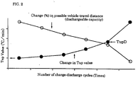
- FIG. 2 is a graph of test results showing the relationship between dischargeable capacity after repeated charge-discharge cycles and average temperature rise speed of the battery during charging.
- FIG. 1 is a block diagram roughly showing a battery deterioration monitor device.
- FIG. 2 is a graph of test results showing the relationship between dischargeable capacity after repeated charge-discharge cycles and average temperature rise speed of the battery during charging. In the graph, the line showing the change in Tup values shows the reference value.
- a battery deterioration monitor device 1 monitors the deterioration of a battery 2 mounted on a motor-operated vehicle such as an electric motor-assisted bicycle.
- a series circuit of the battery 2 and a switch 3 is connected in parallel to a series circuit of a load 4, a switch 5, and a connector 6.
- a charger 7 is connected through the connector 6.
- the battery 2 is a Ni-MH secondary battery for example.
- the load 4 is an electric motor or the like.
- the switches 3 and 5 are controlled with charge-discharge control means 26 in a controller 8. To run the electric motor-operated vehicle, the switches 3 and 5 are closed to discharge electric power to the load 4. The control means 26 also controls the amount of electric discharge to the load 4 during the running. When the electric motor-operated vehicle is stopped for charging at night for example, the battery 2 is connected through the connector 6 to a charger 7, and the charge-discharge controller 26 controls to close the switch 3 and open the switch 5 so that the battery 2 is charged.
- charge-discharge cycle of the battery 2 relative to the load 4 is repeated (cyclic uses) with commands from the charge-discharge controller 26 of the controller 8.
- a voltage sensor 9 detects the voltage of the battery 2 and the voltage information is sent to the charge-discharge control means 26 so that a voltage - ⁇ V is detected during charging, and a final voltage is detected during discharging.
- the temperature of the battery being charged is monitored with a temperature sensor 10 and the temperature information is sent to battery temperature detection means 21 and the charge-discharge control means 26 of the controller 8.
- the controller 8 comprises; reference value storage means 20, battery temperature detection means 21, battery temperature rise speed calculation means 22, and battery deterioration degree determination means 23.
- the reference value storage means 20 stores in advance the reference value (the line in FIG. showing the change in the value of Tup) of the average temperature rise speed of the battery 2.
- the battery temperature detection means 21 calculates the battery temperature using the temperature information from the temperature sensor 10.
- the battery temperature rise speed calculation means 22 measures the temperature of the battery 2 during charging and calculates the average temperature rise speed of the battery 2. In this embodiment, in the Ni-MH battery for example, at the time of charging at a constant current, the first step charging is finished by the detection of a voltage - ⁇ V, or dT/dt, and the battery temperature, and moves on to the next charging.
- the battery temperature (Ts) at the start of constant current charging and the battery temperature (T10) after for example 10 minutes from the charging start are measured, and the average temperature rise speed of the battery 2 over the 10 minutes (°C/min) is calculated as the battery temperature (T10) after 10 minutes from the charging start minus the battery temperature at the charging start divided by 10 minutes.
- the battery deterioration degree determination means 23 determines the deterioration degree of the battery 2 by comparing the actual value of the average temperature rise speed of the battery 2 with the reference value of the average temperature rise speed of the battery 2. That is to say, the state of deterioration of the battery 2 is determined by comparing the actual average temperature rise speed value Tup of the battery 2 with the average temperature rise speed value Tup which has been stored in advance.
- the period of time for calculating the average temperature rise speed of the battery 2 is not limited to 10 minutes used in this embodiment. However, for improving the accuracy, 5 minutes or longer is preferable.
- the battery temperature rise speed may be determined accurately with the charging time of 10 minutes, which applies to all the Ni-MH batteries.
- the battery deterioration monitor device 1 is also provided with deterioration level display means 24 for displaying the determined deterioration level and battery deterioration warning means 25 for issuing battery deterioration warning.
- the degree of battery deterioration is determined with the controller 8 and the deterioration level is displayed with the deterioration level display means 24.
- the deterioration level display indicates how many cycles of discharge may be made or how many kilometers the vehicle may run from now on in either analog or digital form.
- battery deterioration warning is issued from the battery deterioration warning means 25.
- the battery deterioration warning may be issued by either a lamp or a buzzer. In this way, using the simple device of the deterioration level display means 24 or the battery deterioration Warning means 25, the user is reliably alerted to the battery replacement timing or the necessity for maintenance.
- the reference value is the curve showing the change in the Tup value of FIG. 2.
- this invention is not limited to such an arrangement but for example also includes an arrangement in which only one point of TupD is stored as a reference value and display or warning is issued only when the actual average temperature rise speed Tup reaches the TupD, or an arrangement in which reference values of several points on the curve of FIG. 2 are stored in addition to the TupD and display is carried out every time the Tup reaches respective points.
- the device for monitoring the deterioration of the battery is mounted on the electric motor-operated vehicle such as the electric motor-assisted bicycle and informs the rider of the battery replacement timing and the necessity for maintenance based on accurate information on the degree of deterioration in the battery capacity determined easily and accurately irrespective of ambient temperatures at which the battery is charged and discharged by comparing the actual value of average battery temperature rise speed with the reference value of average battery temperature rise speed. Also, the degree of battery deterioration may be accurately determined by calculating the average battery temperature rise speed. Furthermore, displaying the deterioration level and/or warning the battery deterioration make it possible to make the user aware of the battery replacement timing and the necessity for maintenance using a simple device.
Landscapes
- Engineering & Computer Science (AREA)
- Manufacturing & Machinery (AREA)
- Chemical & Material Sciences (AREA)
- Chemical Kinetics & Catalysis (AREA)
- Electrochemistry (AREA)
- General Chemical & Material Sciences (AREA)
- Power Engineering (AREA)
- Physics & Mathematics (AREA)
- General Physics & Mathematics (AREA)
- Charge And Discharge Circuits For Batteries Or The Like (AREA)
- Secondary Cells (AREA)
- Electric Propulsion And Braking For Vehicles (AREA)
- Tests Of Electric Status Of Batteries (AREA)
Applications Claiming Priority (3)
| Application Number | Priority Date | Filing Date | Title |
|---|---|---|---|
| JP11942/96 | 1996-01-26 | ||
| JP1194296 | 1996-01-26 | ||
| PCT/JP1997/000169 WO1997027495A1 (en) | 1996-01-26 | 1997-01-27 | Method and device for monitoring deterioration of battery |
Publications (2)
| Publication Number | Publication Date |
|---|---|
| EP0818687A1 true EP0818687A1 (de) | 1998-01-14 |
| EP0818687A4 EP0818687A4 (de) | 1999-05-12 |
Family
ID=11791713
Family Applications (1)
| Application Number | Title | Priority Date | Filing Date |
|---|---|---|---|
| EP97901260A Withdrawn EP0818687A4 (de) | 1996-01-26 | 1997-01-27 | Verfahren und vorrichtung zur überwachung der verschlechterung einer batterie |
Country Status (6)
| Country | Link |
|---|---|
| US (1) | US5886527A (de) |
| EP (1) | EP0818687A4 (de) |
| JP (1) | JP3804027B2 (de) |
| CN (1) | CN1085842C (de) |
| TW (1) | TW348325B (de) |
| WO (1) | WO1997027495A1 (de) |
Cited By (1)
| Publication number | Priority date | Publication date | Assignee | Title |
|---|---|---|---|---|
| WO2001050543A1 (en) * | 1999-12-29 | 2001-07-12 | 3M Innovative Properties Company | Method and apparatus for characterizing high-energy electrochemical cells using power functions obtained from calorimetry |
Families Citing this family (44)
| Publication number | Priority date | Publication date | Assignee | Title |
|---|---|---|---|---|
| TW392384B (en) * | 1997-11-20 | 2000-06-01 | Hitachi Koki Kk | A battery charging apparatus with error detection |
| JP3378189B2 (ja) * | 1998-02-28 | 2003-02-17 | 株式会社マキタ | 充電装置及び充電方法 |
| JP3506916B2 (ja) | 1998-07-03 | 2004-03-15 | 株式会社マキタ | 充電装置 |
| JP3929243B2 (ja) * | 1998-10-15 | 2007-06-13 | ヤマハ発動機株式会社 | 電動車両用電源システム |
| JP3495636B2 (ja) | 1999-03-25 | 2004-02-09 | 株式会社マキタ | 充電装置 |
| JP3495637B2 (ja) * | 1999-03-26 | 2004-02-09 | 株式会社マキタ | 充電装置及び充電方式 |
| US6476584B2 (en) | 1999-03-25 | 2002-11-05 | Makita Corporation | Battery charger and battery charging method |
| EP1100172A3 (de) | 1999-11-10 | 2004-10-13 | Makita Corporation | Batterieladevorrichtung |
| JP3581064B2 (ja) | 1999-11-10 | 2004-10-27 | 株式会社マキタ | 充電装置 |
| JP3638483B2 (ja) | 1999-11-10 | 2005-04-13 | 株式会社マキタ | 充電装置及び充電方式 |
| JP3652191B2 (ja) | 1999-11-10 | 2005-05-25 | 株式会社マキタ | 充電装置 |
| JP2001211559A (ja) | 2000-01-24 | 2001-08-03 | Makita Corp | 充電装置 |
| EP1128517A3 (de) * | 2000-02-24 | 2003-12-10 | Makita Corporation | Adapter für wiederaufladbare Batteriepacks |
| JP4001708B2 (ja) | 2000-04-28 | 2007-10-31 | 松下電器産業株式会社 | 二次電池の交換方法 |
| JP2001339868A (ja) * | 2000-05-30 | 2001-12-07 | Sanyo Electric Co Ltd | 電池の充放電制御方法 |
| JP3807965B2 (ja) * | 2001-09-19 | 2006-08-09 | インターナショナル・ビジネス・マシーンズ・コーポレーション | インテリジェント電池、電気機器、コンピュータ装置及び電池の劣化度を求める方法 |
| US6462551B1 (en) | 2002-01-18 | 2002-10-08 | Ford Global Technologies, Inc. | Method and system to ensure full functionality of battery pack assembly using thermal imaging |
| DE20311221U1 (de) * | 2003-07-22 | 2003-09-25 | Rose & Krieger Gmbh Co Kg | Steuereinheit |
| JP4576903B2 (ja) * | 2004-06-29 | 2010-11-10 | 三菱化学株式会社 | 温度分布評価方法並びにシミュレーション装置及びシミュレーションプログラム |
| KR100686794B1 (ko) | 2005-01-25 | 2007-02-23 | 삼성에스디아이 주식회사 | 배터리팩의 모니터링 장치 및 그 방법 |
| JP5220269B2 (ja) * | 2005-09-16 | 2013-06-26 | 古河電気工業株式会社 | 蓄電池の劣化状態・充電状態の検知方法及びその装置 |
| JP5008863B2 (ja) * | 2005-11-30 | 2012-08-22 | プライムアースEvエナジー株式会社 | 二次電池用の制御装置、二次電池の温度推定方法を用いた二次電池の劣化判定方法 |
| CN101512364A (zh) * | 2006-08-30 | 2009-08-19 | 丰田自动车株式会社 | 蓄电装置的劣化评价系统、车辆、蓄电装置的劣化评价方法以及储存有用于使计算机执行该劣化评价方法的程序的计算机能够读取的存储介质 |
| JP4703593B2 (ja) * | 2007-03-23 | 2011-06-15 | 株式会社豊田中央研究所 | 二次電池の状態推定装置 |
| JP2009049005A (ja) * | 2007-07-26 | 2009-03-05 | Panasonic Corp | 電池の内部短絡検知装置および方法、電池パック並びに電子機器システム |
| JP5439298B2 (ja) * | 2010-06-30 | 2014-03-12 | 本田技研工業株式会社 | 電動車両における放電制御装置 |
| JP5174111B2 (ja) * | 2010-09-27 | 2013-04-03 | 三菱重工業株式会社 | 電池システム |
| JP5742607B2 (ja) | 2011-09-08 | 2015-07-01 | 三菱自動車工業株式会社 | ハイブリッド電気自動車の制御装置 |
| JP6011541B2 (ja) * | 2011-10-04 | 2016-10-19 | トヨタ自動車株式会社 | 充電制御装置および充電制御方法 |
| JP5880008B2 (ja) * | 2011-12-19 | 2016-03-08 | マツダ株式会社 | 車載用電源の制御装置 |
| US9797784B2 (en) | 2012-03-07 | 2017-10-24 | Apple Inc. | Communication and monitoring of a battery via a single wire |
| US9599519B2 (en) * | 2012-03-07 | 2017-03-21 | Apple Inc. | Charging a battery based on stored battery characteristics |
| JP6048448B2 (ja) * | 2014-05-22 | 2016-12-21 | トヨタ自動車株式会社 | 中古二次電池の再構成品適用判定方法及び組電池再構成品の再構成方法 |
| KR101610507B1 (ko) * | 2014-09-18 | 2016-04-07 | 현대자동차주식회사 | 차량의 고전압 배터리 열화 진단 장치 및 방법 |
| JP6664872B2 (ja) * | 2014-10-28 | 2020-03-13 | 株式会社Gbs | 充電装置、充電プログラム、充電方法 |
| CN104777431B (zh) * | 2015-04-30 | 2018-07-17 | 大连楼兰科技股份有限公司 | 基于obd接口的车辆蓄电池劣化检测设备及方法 |
| CN105137316B (zh) * | 2015-06-04 | 2018-05-22 | 科力远混合动力技术有限公司 | 一种电池劣化的监控方法 |
| JP2017218975A (ja) * | 2016-06-08 | 2017-12-14 | 三菱電機株式会社 | 劣化診断装置 |
| CN107015154B (zh) * | 2017-03-23 | 2019-06-07 | 重庆工程职业技术学院 | 一种准确测量电池容量的方法 |
| JP6874666B2 (ja) * | 2017-12-14 | 2021-05-19 | トヨタ自動車株式会社 | 電池情報処理装置、電池製造支援装置、組電池、電池情報処理方法、及び組電池の製造方法 |
| CN108318824A (zh) * | 2018-01-15 | 2018-07-24 | 清华四川能源互联网研究院 | 一种电池寿命监测装置及其方法 |
| JP6944647B2 (ja) * | 2018-01-30 | 2021-10-06 | トヨタ自動車株式会社 | 電池パックの断線判定システム |
| JP7243123B2 (ja) * | 2018-10-19 | 2023-03-22 | トヨタ自動車株式会社 | 車両 |
| JP7205430B2 (ja) * | 2019-09-20 | 2023-01-17 | 株式会社豊田自動織機 | 産業車両のバッテリ温度調節システム |
Citations (2)
| Publication number | Priority date | Publication date | Assignee | Title |
|---|---|---|---|---|
| US3852652A (en) * | 1973-08-06 | 1974-12-03 | Motorola Inc | Rapid battery charging system and method |
| JPH03131780A (ja) * | 1989-10-17 | 1991-06-05 | Fujikura Ltd | 蓄電池内蔵機器パッケージおよび蓄電池の劣化判定方法 |
Family Cites Families (11)
| Publication number | Priority date | Publication date | Assignee | Title |
|---|---|---|---|---|
| JPH0681427B2 (ja) * | 1986-02-20 | 1994-10-12 | 松下電工株式会社 | 充電器の制御回路 |
| JPH0648290B2 (ja) * | 1989-05-31 | 1994-06-22 | 株式会社ユアサコーポレーション | 密閉形鉛蓄電池の寿命表示部を備えた電源装置 |
| JPH03137780A (ja) * | 1989-10-24 | 1991-06-12 | Mitsubishi Electric Corp | 非接触型icカード |
| JP3090461B2 (ja) * | 1990-08-27 | 2000-09-18 | 松下電工株式会社 | 充電回路 |
| US5686815A (en) * | 1991-02-14 | 1997-11-11 | Chartec Laboratories A/S | Method and apparatus for controlling the charging of a rechargeable battery to ensure that full charge is achieved without damaging the battery |
| JP2732204B2 (ja) * | 1993-09-29 | 1998-03-25 | 株式会社ジップチャージ | 二次電池の高速充電方法及びその装置 |
| JPH07130378A (ja) * | 1993-10-28 | 1995-05-19 | Canon Inc | 部品またはこの部品を用いたユニットの寿命推定装置 |
| JP3214782B2 (ja) * | 1994-07-15 | 2001-10-02 | トヨタ自動車株式会社 | 蓄電池管理装置 |
| JP3136926B2 (ja) * | 1994-11-08 | 2001-02-19 | 松下電器産業株式会社 | 蓄電池の状態管理システム |
| JP3285720B2 (ja) * | 1994-11-08 | 2002-05-27 | 松下電器産業株式会社 | 組電池の劣化検出方法及び劣化検出装置 |
| JP3129150B2 (ja) * | 1995-06-09 | 2001-01-29 | 松下電器産業株式会社 | 蓄電池の寿命予告装置 |
-
1997
- 1997-01-24 TW TW086100806A patent/TW348325B/zh not_active IP Right Cessation
- 1997-01-27 EP EP97901260A patent/EP0818687A4/de not_active Withdrawn
- 1997-01-27 CN CN97190196A patent/CN1085842C/zh not_active Expired - Fee Related
- 1997-01-27 US US08/913,678 patent/US5886527A/en not_active Expired - Fee Related
- 1997-01-27 JP JP52673997A patent/JP3804027B2/ja not_active Expired - Lifetime
- 1997-01-27 WO PCT/JP1997/000169 patent/WO1997027495A1/ja not_active Application Discontinuation
Patent Citations (2)
| Publication number | Priority date | Publication date | Assignee | Title |
|---|---|---|---|---|
| US3852652A (en) * | 1973-08-06 | 1974-12-03 | Motorola Inc | Rapid battery charging system and method |
| JPH03131780A (ja) * | 1989-10-17 | 1991-06-05 | Fujikura Ltd | 蓄電池内蔵機器パッケージおよび蓄電池の劣化判定方法 |
Non-Patent Citations (2)
| Title |
|---|
| PATENT ABSTRACTS OF JAPAN vol. 015, no. 347 (P-1246), 3 September 1991 & JP 03 131780 A (FUJIKURA LTD), 5 June 1991 * |
| See also references of WO9727495A1 * |
Cited By (2)
| Publication number | Priority date | Publication date | Assignee | Title |
|---|---|---|---|---|
| WO2001050543A1 (en) * | 1999-12-29 | 2001-07-12 | 3M Innovative Properties Company | Method and apparatus for characterizing high-energy electrochemical cells using power functions obtained from calorimetry |
| US6833707B1 (en) | 1999-12-29 | 2004-12-21 | 3M Innovative Properties Company | Method and apparatus for characterizing high-energy electrochemical cells using power functions obtained from calorimetry |
Also Published As
| Publication number | Publication date |
|---|---|
| TW348325B (en) | 1998-12-21 |
| US5886527A (en) | 1999-03-23 |
| WO1997027495A1 (en) | 1997-07-31 |
| CN1085842C (zh) | 2002-05-29 |
| EP0818687A4 (de) | 1999-05-12 |
| CN1182482A (zh) | 1998-05-20 |
| JP3804027B2 (ja) | 2006-08-02 |
Similar Documents
| Publication | Publication Date | Title |
|---|---|---|
| US5886527A (en) | Method and device for monitoring deterioration of battery | |
| EP0481743B1 (de) | Verfahren, die verbleibende elektrische Ladung der Batterie eines elektrisch betriebenen Fahrzeugs anzuzeigen | |
| US7355411B2 (en) | Method and apparatus for estimating state of charge of secondary battery | |
| EP0225364B1 (de) | Überwachung des zustandes einer batterie | |
| US8788142B2 (en) | Method for the continuous measurement of the efficiency of a battery, especially a battery installed in motor vehicles, and a device utilizing this method | |
| EP0206503B1 (de) | Verfahren und Vorrichtung zur Feststellung des Ladezustandes einer Batterie | |
| EP1314992A2 (de) | Verfahren und Vorrichtung zur Ladezustandskontrolle einer Kraftfahrzeugbatterie | |
| KR102337489B1 (ko) | 전기차량의 배터리 soh 추정 시스템 | |
| US6268712B1 (en) | Method for determining the starting ability of a starter battery in a motor vehicle | |
| US20170269165A1 (en) | Secondary battery state detection device and secondary battery state detection method | |
| US20090001992A1 (en) | Charged State Estimating Device and Charged State Estimating Method of Secondary Battery | |
| US5723971A (en) | Apparatus for charging a battery for a charge time determined based on the depth of discharge | |
| EP2058891B1 (de) | Ladesteuervorrichtung für eine Speicherbatterie | |
| JP2005083970A (ja) | 二次電池の状態検知装置および状態検知方法 | |
| CA2423414C (en) | Battery state of charge indicator | |
| EP1736789A1 (de) | Verfahren und geräte zur schätzung der restkapazität einer speicherbatterie | |
| JP2020079723A (ja) | 二次電池システム | |
| US5608325A (en) | Method of recalibrating a battery energy management processor | |
| US11313911B2 (en) | Secondary battery parameter estimation device, secondary battery parameter estimation method, and program | |
| JPH04368401A (ja) | バッテリーの残存容量表示装置 | |
| JP4144116B2 (ja) | バッテリ充電状態検出装置 | |
| JP3343155B2 (ja) | Ni−MHバッテリの劣化度監視方法及びその装置 | |
| WO2007072988A1 (ja) | 二次電池の劣化判定装置および劣化判定方法 | |
| JP2003254839A (ja) | 温度センサの状態検知装置および状態検知方法 | |
| JP2004245673A (ja) | 蓄電体の残存容量推定方法、装置および蓄電体パック |
Legal Events
| Date | Code | Title | Description |
|---|---|---|---|
| PUAI | Public reference made under article 153(3) epc to a published international application that has entered the european phase |
Free format text: ORIGINAL CODE: 0009012 |
|
| AK | Designated contracting states |
Kind code of ref document: A1 Designated state(s): DE DK ES FR GB IT NL |
|
| 17P | Request for examination filed |
Effective date: 19980123 |
|
| A4 | Supplementary search report drawn up and despatched |
Effective date: 19990331 |
|
| AK | Designated contracting states |
Kind code of ref document: A4 Designated state(s): DE DK ES FR GB IT NL |
|
| 17Q | First examination report despatched |
Effective date: 20040714 |
|
| GRAP | Despatch of communication of intention to grant a patent |
Free format text: ORIGINAL CODE: EPIDOSNIGR1 |
|
| STAA | Information on the status of an ep patent application or granted ep patent |
Free format text: STATUS: THE APPLICATION IS DEEMED TO BE WITHDRAWN |
|
| 18D | Application deemed to be withdrawn |
Effective date: 20051109 |