EP0811301B1 - Vorrichtung und verfahren zur adaptiven vorkompensierung von lautsprecherverzerrungen - Google Patents
Vorrichtung und verfahren zur adaptiven vorkompensierung von lautsprecherverzerrungen Download PDFInfo
- Publication number
- EP0811301B1 EP0811301B1 EP96906451A EP96906451A EP0811301B1 EP 0811301 B1 EP0811301 B1 EP 0811301B1 EP 96906451 A EP96906451 A EP 96906451A EP 96906451 A EP96906451 A EP 96906451A EP 0811301 B1 EP0811301 B1 EP 0811301B1
- Authority
- EP
- European Patent Office
- Prior art keywords
- signal
- echo
- precompensating
- loudspeaker
- filter
- Prior art date
- Legal status (The legal status is an assumption and is not a legal conclusion. Google has not performed a legal analysis and makes no representation as to the accuracy of the status listed.)
- Expired - Lifetime
Links
Images
Classifications
-
- H—ELECTRICITY
- H04—ELECTRIC COMMUNICATION TECHNIQUE
- H04R—LOUDSPEAKERS, MICROPHONES, GRAMOPHONE PICK-UPS OR LIKE ACOUSTIC ELECTROMECHANICAL TRANSDUCERS; ELECTRIC HEARING AIDS; PUBLIC ADDRESS SYSTEMS
- H04R3/00—Circuits for transducers
-
- H—ELECTRICITY
- H04—ELECTRIC COMMUNICATION TECHNIQUE
- H04R—LOUDSPEAKERS, MICROPHONES, GRAMOPHONE PICK-UPS OR LIKE ACOUSTIC ELECTROMECHANICAL TRANSDUCERS; ELECTRIC HEARING AIDS; PUBLIC ADDRESS SYSTEMS
- H04R3/00—Circuits for transducers
- H04R3/002—Damping circuit arrangements for transducers, e.g. motional feedback circuits
-
- H—ELECTRICITY
- H04—ELECTRIC COMMUNICATION TECHNIQUE
- H04M—TELEPHONIC COMMUNICATION
- H04M9/00—Arrangements for interconnection not involving centralised switching
- H04M9/08—Two-way loud-speaking telephone systems with means for conditioning the signal, e.g. for suppressing echoes for one or both directions of traffic
Definitions
- This invention relates to the field of audio systems, and more particularly to the suppression of sound distortion in a loudspeaker.
- An audio system includes an output transducer, such as a loudspeaker, to produce a sound pressure wave in response to an input signal representative of a desired sound pressure wave.
- an output transducer such as a loudspeaker
- Most loudspeakers generate an actual sound pressure wave that differs from the desired sound pressure wave represented by the input signal. This difference is due, in part, to non-linear aspects of the loudspeaker.
- the diaphragm of a loudspeaker has a non-linear stress-strain curve.
- the motion of the diaphragm results in the delay modulation of higher frequencies by lower frequencies. Accordingly, there have been efforts in the art to compensate for these and other factors which cause a loudspeaker to produce an actual sound pressure wave which is different from the desired sound pressure wave.
- United States Patents No. 4,426,552 and No. 4,340,778 both to Cowans et al. and both entitled “Speaker Distortion Compensator,” disclose means coupled to each speaker in a system for compensating for mass, compliance, and damping.
- the processing circuits are exemplified by active and passive circuits which provide a feedforward component which nullifies the spurious emanations that would otherwise develop as the loudspeaker diaphragm attempts to follow complex motions that are otherwise impermissible because of its dynamics.
- United States Patent No. 4,709,391 to Kaiser et al . entitled "Arrangement For Converting An Electric Signal Into An Acoustic Signal Or Vice Versa And A Non-Linear Network For Use In The Arrangement” discloses an arrangement including means for reducing distortion in the output signal.
- the reducing means comprise a non-linear network arranged for reducing non-linear distortion by compensating for at least a second or higher order distortion component in the output signal.
- the article by de Vries et al. entitled “Digital Compensation of Nonlinear Distortion in Loudspeakers,” IEEE, 1993, pp. I-165 to I-167 discloses a method to compensate for non-linear distortions produced by a loudspeaker in real-time by non-linear digital signal processing.
- An electrical equivalent circuit of an electrodynamic loudspeaker is developed resulting in a linear lumped parameter model.
- the linear model is extended to include non-linear effects, and an inverse circuit is implemented in real-time on a digital signal processor.
- United States Patent No. 5,131,032 describes an echo canceller and a communication apparatus which is capable of stably reproducing sounds other than a received sound during speech through a telephone and the received sound is heard by the other party to the speech.
- an adaptive precompensating method and system which modifies the operation of a precompensating filter in an audio system in response to the output of the loudspeaker. Accordingly, the precompensating filter operations are not fixed but rather are varied over time. Accordingly, the precompensating filter operation can be modified to account for aging of the loudspeaker and other effects such as changes in the environment in which the system is operated.
- a model of the electrical characteristics of a loudspeaker is used to derive an approximation of a transfer function of the loudspeaker.
- An inverse of this transfer function is performed by the precompensating filter on the input signal which represents the desired loudspeaker output.
- the precompensated signal is then applied to the loudspeaker. Accordingly, the output of the loudspeaker more closely resembles the desired loudspeaker output.
- An input transducer such as a microphone, is used to provide a feedback loop from the loudspeaker to the precompensating filter so that the precompensating filter can compare the actual loudspeaker output with the desired output. This feedback allows the precompensating filter to adapt the approximated inverse transfer function in order to improve its operation.
- the present invention is preferably applied to a loudspeaker cellular radiotelephone designed for hands free operation.
- This application is particularly appropriate because the loudspeaker telephone includes a loudspeaker and a microphone.
- the loudspeaker is typically constrained in its size and required to produce a sound pressure waveform having a relatively high amplitude, the distortions produced by the loudspeaker can be more pronounced than the distortions produced in other audio systems.
- loudspeaker cellular telephones are often used in inherently noisy environments, such as an automobile, making their use difficult to begin with. Accordingly, the precompensating filter can be used to reduce the distortions generated by the small loudspeakers used in these applications thereby making the reproduced sound more understandable.
- the present invention may also be applied to hi-fi audio systems by including a microphone to provide feedback.
- the system can be used to monitor the loudspeaker output and adapt the operation of the precompensating filter as needed.
- the system can adapt its operation to account for aging, as well as environmental changes such as the acoustical characteristics of the space in which the system operates.
- the operation of the present invention can be further improved by including an echo filter which provides an estimate of the echo or ring-around signal from the loudspeaker to the microphone. This estimated echo signal is then subtracted from, or combined with, the sound signal generated by the microphone, thereby reducing the echo portion of the sound signal in the feedback loop to the precompensating filter. Accordingly, the precompensating filter can more accurately modify its operation.
- the echo filter can be provided with another feedback loop. By comparing the estimated echo signal with the actual echo signal, the echo filter can modify its operation in order to further reduce the echo portion of the signal. The reduction of non-linear aspects of the loudspeaker by the precompensating filter allows the echo filter to more accurately modify its own operation.
- both the precompensating filter and the echo filter are implemented in a digital signal processor ("DSP").
- DSP digital signal processor
- analog-to-digital and digital-to-analog converters can be used.
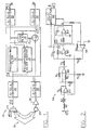
- the audio system 10 shown in Figure 1 includes precompensating means such as adaptive precompensating filter 12 for reducing the effects of non-linear aspects of the output transducer means, preferably implemented as loudspeaker 14 .
- the system also includes an adaptive echo filter 16 for reducing environmental distortions due to the multi-path channel 18 from the loudspeaker 14 to the input transducer means, preferably implemented as microphone 20.
- the precompensating filter and echo filter enhance the operation of each other.
- the loudspeaker 14 characteristics can be represented by a transfer function H having both linear and non-linear components. By approximating an inverse H -1 of the loudspeaker transfer function H, the precompensating filter 12 is able to reduce the non-linear distortions generated by the loudspeaker.
- a precompensating filter modifier 34 in the feedback loop from the precompensating filter 12 through the loudspeaker 14 and multi-path channel 18 to the microphone 20 and back to the precompensating filter 12 can modify or adapt the approximated inverse transfer function H -1 of the precompensating filter to further reduce non-linear distortions generated by the loudspeaker.
- the precompensating filter modifier can include a memory for storing portions of the various waveforms such as W(T), V(t), Z(t), and E(t) for comparison.
- the echo filter 16 may be used to generate an approximation of environmental distortions, such as echo or ring-around, occurring over multi-path acoustic channel 18 between the loudspeaker 14 and the microphone 20.
- This approximation can be combined with the sound signal generated by the microphone 20 through combination or subtraction means, such as subtractor 22 , to reduce undesired environmental distortions such as echo or ring-around in the signal.
- Modification means including a feedback loop from the echo filter 16 through the subtractor 22 and back to the echo filter 16 , allows the echo filter to modify its operation so as to further reduce the effects of environmental distortions.
- the echo filter 16 reduces feedback of the loudspeaker output to the distant party.
- the precompensating filter 12 reduces non-linear distortions that could not otherwise be accounted for by the echo filter 16 , while the echo filter 16 reduces environmental distortions that would otherwise be unaccounted for by the precompensating filter 12 .
- each of the precompensating filter and the echo filter reduce distortions in the feedback loop for the other. Accordingly, the operation of each of the precompensating filter and the echo filter can be modified to more closely approximate a desired level of operation.
- Figure 1 also shows that the precompensating filter 12 , the echo filter 16 , precompensating filter modifier 34 , and the subtractor 22 may be incorporated into a single digital signal processor 24 ("DSP").
- DSP digital signal processor
- the invention may require a digital-to-analog (“D-to-A") converter 26 between the DSP 24 and the loudspeaker 14 and an analog-to-digital (“A-to-D”) converter 28 between the microphone 20 and the DSP 24.
- D-to-A converter 26 digital-to-analog
- A-to-D analog-to-digital converter 28 between the microphone 20 and the DSP 24.
- A-to-D converter 30 and D-to-A converter 32 may be required if signals are supplied from or to an analog source.
- the system may also include an amplifier 36.
- an input speech waveform W(t) representative of the distant party speech is received by the telephone transceiver from a cellular telephone system base station, and after suitable processing is applied at input node 36 .
- processing can include demodulation of a digitally modulated radio signal, error correction decoding, and speech decoding using, for example, a Residually Excited Linear Prediction (“RELP”) or Vector Set Excited Linear Prediction (“VSELP”) speech synthesizer.
- RELP Residually Excited Linear Prediction
- VSELP Vector Set Excited Linear Prediction
- the waveform W(t) is the result of such processing, and may be in a digital format which is more suitable for processing by the echo canceler of the present invention.
- Precompensating filter 12 reduces loudspeaker distortions while echo filter 16 reduces echo and ring-around.
- the training of the precompensating and echo filters can be performed continuously.
- the training function is performed when only the distant party is speaking so that the relevant signals may be more easily isolated. This can be accomplished by comparing the input signal and the sound signal to determine when the microphone is receiving significant sound pressure waves generated by the loudspeaker alone and adapting the precompensating filter at that time.
- a device that determines when the signal out of the microphone is substantially derived from acoustic feed back is discussed, for example, in U.S. Patent No. 5,263,019 to Chu entitled "Method and Apparatus for Estimating the Level of Acoustic Feedback Between a Loudspeaker and Microphone," the disclosure of which is hereby incorporated in its entirety herein by reference.
- the training function may be preformed periodically by using test signals.
- the input signal at node 36 may be supplied by any of a number of digital or analog audio components such as a tuner, tape player, compact disk player, etc.
- the precompensating filter and echo filter work together to reduce loudspeaker distortions.
- the training function is preferably performed periodically using test signals which may be supplied by a tape or other signal input means.
- FIG 2 shows an analog model of the electrical characteristics of a typical loudspeaker 14 .
- An electrical input signal is applied at input node A to create a current through the loudspeaker coil.
- the loudspeaker input signal is a precompensated input signal V(t) from the precompensating filter 12 shown in Figure 1 .
- the current flow is opposed by the coil resistance 40 and coil inductance 42 , as well as the back EMF induced by the coil velocity in the magnetic field.
- the voltage at node C may be equal to the back-EMF as well as being representative of the coil velocity.
- the back EMF from node C is presented in opposition to the drive voltage at input node A by connection to the positive input of differencing operational amplifier 44 .
- the output of amplifier 44 is the sum of the back EMF from node C and a term proportional to the current in the coil.
- Amplifier 46 subtracts the back EMF to yield a voltage representing the current in the coil only, and by suitable choice of arbitrary units, this voltage also represents the force the coil exerts on the loudspeaker diaphragm by the current reacting with the magnetic field produced by the loudspeaker magnet.
- diaphragm is used throughout this specification in its broadest sense so as to include a planar diaphragm, a dome shaped diaphragm, or a cone shaped diaphragm.
- Operational amplifier 48 has a feedback capacitor 50 representing the diaphragm's mass and a feedback resistor 52, which might be non-linear, representing the air resistance acting against the diaphragm.
- the current flow through resistor 52 opposes the accelerating force and relates to the air pressure wave created by the diaphragm movement.
- Current sensor 54 generates a signal at node C' which represents this air pressure wave created by the diaphragm movement.
- the pressure wave emanates from a moving object, the diaphragm.
- the diaphragm When the diaphragm is instantaneously displaced to the front of the loudspeaker, it will be closer to a listener in front of the loudspeaker. Accordingly, sound waves will reach the listener with a shorter time delay than when the diaphragm is displaced toward the rear of the loudspeaker.
- Diaphragm displacements occur with greatest amplitude at low frequencies giving rise to the non-linear phenomenon of delay modulation (also known as phase modulation) of higher frequencies by lower frequencies.
- a signal representative of the diaphragm displacement is generated at node D by resistance 60, capacitance 62, and operational amplifier 64 , which together make up integrator 65.
- the pressure wave signal from the diaphragm generated at node C' is subjected to delay modulation produced by delay modulator 66 according to the diaphragm displacement signal generated at node D in order to produce the net sound pressure waveform at output node B that is transmitted to a listener.
- the diaphragm displacement signal generated at node D is also needed to model the diaphragm spring restoring force that opposes the force exerted by the coil which is represented by the coil force signal generated by operational amplifier 46 .
- the diaphragm spring is expected to exhibit a non-linear stress-strain curve modelled by the non-linear resistor 56.
- Operational amplifier 58 having non-linear resistor 56 in its feedback path, converts the displacement-related signal generated at node D to a restoring force which adds in opposition to the coil force signal at the input of operational amplifier 48 .
- the resistors labeled R 0 may be equal to 1 ohm.
- the sound pressure wave generated at loudspeaker output node B can be predicted from the electrical signal applied to the loudspeaker input node A .
- the model discussed above is used in reverse to determine the electrical signal with which to drive the loudspeaker at input node A so as to obtain a desired sound pressure wave at output node B .
- the loudspeaker model is used to determine an approximate inverse of the transfer function of the loudspeaker. This may be done as described below.
- the desired sound pressure wave is represented by an input signal W(t) which is applied at node 36, and converted to a digital signal by A-to-D converter 30 if necessary.
- the precompensating filter 12 generates a precompensated signal V(t) which is converted to an analog signal by D-to-A converter 26, if necessary. If signal V(t) is correctly generated, the output sound pressure wave W'(t) will be a close approximation of the desired sound pressure wave represented by signal W(t).
- the sound pressure waveform W'(t) is produced at output node B and may be represented by a sequence of numerical samples. These samples are expressed as:
- the voltage across the resistor 52 at node C may be represented by a function F(U(t)).
- the diaphragm displacement samples D(i) should be computed by integrator 65 in units of 1.5 inches. D(i) is expected to be much less than unity with this scaling.
- C(i) - C(i-1) represents the rate of change of voltage at the output of operational amplifier 48
- X represents the diaphragm-mass parameter, capacitor 50 , times dT.
- the non-linear function G(t) represents the diaphragm restoring force versus displacement curve (stress-strain curve).
- the relative magnitudes or scalings of the air-resistance function F(t), the diaphragm-mass parameter X and the function G(t) are assumed to have been correctly chosen so that they may be added in equation (4) with no additional scaling factors.
- V(t) represented by samples, ..., V(i-1), V(i), V(i+1),...
- V i I i * R + I i - I ⁇ i - 1 * L / dT + C i .
- R and L are the coil resistance 40 and inductance 42 respectively.
- a sequence, ..., V(i-2), v(i-1), V(i), ..., of the required input voltage samples may be calculated to produce the sound pressure wave samples, ..., W'(i-2), W'(i-1), W'(i), ..., which closely approximate the desired sound pressure samples represented by, ..., W(i-2), W(i-1), W(i)....
- the linear parameters in the equations shown above can be determined by measurement.
- the determination of the coil resistance and inductance parameters R and Y is straightforward as will be understood by one having ordinary skill in the art.
- the diaphragm mass and linear part of the diaphragm stress-strain curve can be determined by measuring the diaphragm's mechanical resonant frequency and Q factor when the loudspeaker is in its intended housing.
- the small-signal parameters are then fixed and the non-linear parameters dT, representing delay modulation, and G'(D(t)), representing the non-linear part of the stress-strain curve, may be determined by large signal measurements.
- the delay modulation may be determined by using a spectrum analyzer to observe the intermodulation produced on a two-tone test between a low frequency sine wave signal that causes large diaphragm displacements and a high frequency sine wave signal that is most sensitive to phase modulation by the low-frequency diaphragm displacements.
- the non-linear part of the stress-strain curve may be obtained by using a spectrum analyzer to observe the harmonic distortion of a large, low-frequency, sine wave signal as a function of amplitude and finding a function G'(D(t)) by trial and error that explains it.
- the function can be represented in a numerical signal processor such as a DSP by a look-up table.
- this curve can be directly determined by physical measurements of force or DC current required to displace the diaphragm a measured amount.
- the invention may include the provision of a diaphragm displacement or movement sensor for the purpose of assisting in real-time determination or adaptive updating of model parameters.
- a typical stress-strain curve G'(D(t)) may be assumed to be known apart from a scaling factor for a particular loudspeaker.
- the linear model parameters resulting in particular diaphragm mechanical resonances are well known for a particular loudspeaker size and make. Small errors in small-signal parameters that effect small-signal frequency response are not of great consequence since any system is assumed to have some ability to adapt linear frequency responses to provide compensation. For example, a manual equalizer or tone control may be provided.
- the linear frequency response from the loudspeaker to the microphone includes reflections from nearby objects, possible room resonances, and other distortions induced by the environment which are illustrated in Figure 1 by the multi-path acoustic channel 18.
- These environmental distortions known as echo or ring-around can be modeled by an echo filter such as an adaptive finite-impulse-response (FIR) filter.
- FIR adaptive finite-impulse-response
- Adaptive filters used in echo cancellation are discussed, for example in U.S. Patent No. 5,237,562 to Fujii et al . entitled “Echo Path Transition Detection.”
- Other echo cancelers including adaptive echo estimation or a finite impulse response filter are respectively discussed in U.S. Patent No. 5,131,032 to Esaki et al . entitled “Echo Canceler and Communication Apparatus Employing the Same," and U.S. Patent No. 5,084,865 to Koike entitled “Echo Canceller Having FIR and IIR Filters for Canceling Long Tail Echoes.”
- Each of the three above cited patents are hereby incorporated in their entirety herein by reference.
- the modeled distortions can be subtracted from the sound signal generated by the microphone to reduce the environmental distortions.
- the echo or ring-around is, however, imperfectly modeled due, in part, to the non-linear loudspeaker effects discussed above which are not modeled by the echo filter 16. Accordingly, imperfect echo cancellation results.
- the channel from electrical input to the precompensating filter 12 to the microphone 20 output may be linearized such that it is more accurately modeled by the echo filter 16, giving better echo cancellation.
- Figure 1 shows an input signal W(t) representative of a desired sound pressure wave being applied to a precompensating filter 12 according to the foregoing discussion in order to generate a precompensated loudspeaker input signal V(t).
- the precompensating filter 12 implements an inverse operation H -1 of an estimate H of the true non-linear transfer function H of the loudspeaker.
- precompensating filter modifier 34 which may include a memory.
- precompensating filter modifier 34 may include a memory.
- large signal segments of these signals are preferably collected.
- the ratio of microphone output sound signal to loudspeaker signal may be processed to determine which party is speaking.
- the signal segments should preferably be selected when only the distant party is speaking so that the microphone sound signal Z(t) does not contain locally generated speech. Accordingly, the microphone sound signal Z(t) will be made up almost entirely of echo or ring-around components.
- the coefficients a i of the echo filter 16 are then chosen so that the filter transforms the segment of signal W(t) to as close a match as possible to the echo portion of signal Z(t). This transformed signal is labeled Z'(t).
- a modified waveform W'(t) is calculated using the coefficients that would be transformed to the actual echo portion of signal Z(t).
- One method of deriving the waveform W'(t) is to use the best available FIR approximation to the inverse FIR filter, or to solve a set of equations for W'(t) samples to be input in order to obtain a close match to Z(t) samples at the output.
- a model that correctly precompensates at least one input signal segment W(t) may be obtained such that the overall channel from precompensating filter input through the loudspeaker and multi-path channel is approximately a linear channel. If the waveform W'(t) segment is sufficiently representative of all possible waveforms, then the precompensating filter operation may be correct for all other waveforms. This criteria may be achieved if the segments are long enough to contain many examples of waveforms and spectra.
- model parameters can be updated so that a given precompensated input signal V(t) applied to the input node A of the loudspeaker modeled in Figure 2 is transformed to a second given waveform W'(t) at output node B of the loudspeaker.
- the model of Figure 2 is first used to compute the signals at nodes C ' and D from the precompensated input signal V(t) applied at input node A .
- the inverse of equation (7) is obtained merely by reversing the sign of the delay modulation.
- Equation (6) and (7) are used to compute samples C(i) and D(i) of signals C(t) and D(t) that would produce the desired sound pressure waveform. Equation (10) is then used to compute samples I(i) of the signal I(t) given C(i) and the given signal V(t) as samples V(i).
- the coefficients may be determined by a conventional least-squares polynomial fitting procedure. Note that this also updates the linear parameter G 0 , which affects the modeling of the mechanical resonant frequency. Alternately, the Go parameter can be left unchanged and only the non-linear coefficients G 1 , G 2 , ... updated.
- the method discussed above may require the calculation of an input waveform W'(t) to a given filter in order to obtain a given output signal Z(t) as accurately as possible. This effectively describes inverting the filter transfer function, which may not always be possible. Approximations to the inverse filter may be used if this approach is taken. These approximations may be computed, for example, by the techniques disclosed in Roberts & Mullis "Digital Signal Processing” , Addison-Wesley (1987), Chapter 7, the disclosure of which is incorporated herein by reference.
- the first part of the equation C(i) is the non-delay-modulated waveform, and the second part is a product of the derivative and the integral of the same which is scaled by the delay modulation coefficient dT.
- the echo filter Since the echo filter is linear, its output Z'(t) is the sum of outputs obtained by filtering the first and second parts of equation (13) separately.
- C(i) and Q(i) are then filtered separately by using the echo filter 16 in the forward direction to obtain samples of two signals Z 1 (t) and Z 2 (t) respectively.
- the discrete-time samples are denoted by Z 1 (i) and Z 2 (i).
- ALPHA times Z 1 (t) plus BETA times Z 2 (t) is now calculated such that (ALPHA)*Z 1 (t) + (BETA)*Z 2 (t) equals Z(t) as closely as possible.
- ALPHA de - bf ad - bc
- BETA af - ce ad - bc
- the output waveforms W(t) and W 1 (t) are calculated with the original and a slightly modified polynomial coefficient. For example, the cubic coefficient G 2 is increased by 1/16th of its value.
- the change in waveform W 1 (t)-W(t) is then filtered by the echo filter 16 to obtain a signal Z 3 (t).
- the amount GAMMA of Z 3 (t) is then found which causes Z'(t) to more closely match Z(t).
- a non-linear model of a loudspeaker may be modeled in terms of a number of parameters and inverted to produce a procedure for generating a precompensated loudspeaker input signal that will reduce the effects of loudspeaker distortion. It has also been disclosed how loudspeaker linear and non-linear model parameters can be measured for the purpose of tuning a precompensating filter, on installation for example. This specification also discloses how sound can be converted to a microphone output sound signal by using a microphone and then used to adaptively update the loudspeaker model parameters in order to successively improve the overall linearity of the combination of the loudspeaker and precompensating means. Such an invention can be useful in providing audio systems with improved sound fidelity as well as in improving echo cancellation in a loudspeaker telephone or cellular radiotelephone having a full-duplex, hands-free function.
Landscapes
- Engineering & Computer Science (AREA)
- Signal Processing (AREA)
- Physics & Mathematics (AREA)
- Acoustics & Sound (AREA)
- Circuit For Audible Band Transducer (AREA)
- Soundproofing, Sound Blocking, And Sound Damping (AREA)
- Amplifiers (AREA)
- Cable Transmission Systems, Equalization Of Radio And Reduction Of Echo (AREA)
Claims (13)
- Adaptives vorkompensierendes Lautsprechertelefon mit einem Lautsprecher (14) zum Erzeugen einer Schalldruckwelle als Antwort auf ein Audioeingangssignal, das an einen Audioeingang davon angelegt ist, wobei die Schalldruckwelle eine erwünschte lineare Komponente enthält, die eine lineare Funktion des Audioeingangssignals ist, und eine unerwünschte nichtlineare Komponente, die eine nichtlineare Funktion des Audioeingangssignals ist, und ein Mikrofon (20) zum Umwandeln der Schalldruckwelle in ein Schallsignal, wobei das adaptive vorkompensierende Lautsprechertelefon umfasst:ein vorkompensierendes Filter (12) zum Vorkompensieren eines Eingangssignals, das für die erwünschte lineare Komponente repräsentativ ist, um ein vorkompensiertes Ausgangssignal zu erzeugen, und zum Anlegen des vorkompensierten Ausgangssignals an den Audioeingang, sodass die unerwünschte nichtlineare Komponente reduziert wird; undeinen Regler (34) des vorkompensierenden Filters, ansprechempfindlich auf das Schallsignal und das Eingangssignal zum Regeln des vorkompensierenden Filters, um die unerwünschte nichtlineare Komponente weiter zu reduzieren.
- Adaptives vorkompensierendes Audiosystem nach Anspruch 1, außerdem umfassend:ein Echofilter (16), ansprechempfindlich für das Eingangssignal, zum Erzeugen eines geschätzten Echosignals;ein Subtraktionsmittel (22) zum Subtrahieren des geschätzten Echosignals vom Schallsignal, sodass ein Echoanteil des Schallsignals reduziert wird, um ein reduziertes Echoschallsignal bereitzustellen und zum Bereitstellen des reduzierten Echoschallsignals für den Regler des vorkompensierenden Filters; undworin der Regler des vorkompensierenden Filters außerdem für das reduzierte Echoschallsignal ansprechempfindlich ist.
- Adaptives vorkompensierendes Audiosystem nach Anspruch 2, worin das Echofilter (16) ein Regelmittel zum Regeln des Echofilters umfasst als Antwort auf das Eingangssignal, das geschätzte Echosignal und das Schallsignal, um den Echoanteil des Schallsignals weiter zu reduzieren.
- Adaptives vorkompensierendes Audiosystem nach Anspruch 2, worin das Echofilter (16) ein FIR-Filter (Transversalfilter) umfasst.
- Adaptives vorkompensierendes Audiosystem nach Anspruch 1, worin das vorkompensierende Filter (12) einen digitalen Signalprozessor umfasst.
- Adaptives vorkompensierendes Audiosystem nach Anspruch 1, worin das vorkompensierende Filter (12) ein Mittel zum Ausführen einer Transformation des Eingangssignals umfasst, um das vorkompensierte Ausgangssignal zu erzeugen, wobei die Transformation eine Schätzung einer nichtlinearen Transferfunktion des Lautsprechers ist.
- Adaptives vorkompensierendes Audiosystem nach Anspruch 6, worin die nichtlineare Transferfunktion eine der Folgenden repräsentiert: eine Verzögerungsmodulation des Lautsprechers und eine Spannung-Dehnung-Kurve der Membran des Lautsprechers.
- Adaptives vorkompensierendes Audiosystem nach Anspruch 1, worin der Regler (34) des vorkompensierenden Filters einen Eingangs-Sender-Empfänger (20) zum Umwandeln der Schalldruckwelle in ein Schallsignal umfasst.
- Verfahren zum adaptiven Vorkompensieren für Verzerrung in einem Audiosystem einschließlich eines Lautsprechers, der als Antwort auf ein Audioeingangssignal eine Schalldruckwelle erzeugt, wobei die Schalldruckwelle eine erwünschte lineare Komponente enthält, die eine lineare Funktion des Audioeingangssignals ist, und eine unerwünschte nichtlineare Komponente, die eine nichtlineare Funktion des Audioeingangssignals ist, wobei das Verfahren folgende Schritte umfasst:Bereitstellen eines Eingangssignals, das für die erwünschte lineare Komponente repräsentativ ist;Ausführen einer Vorkompensationsfunktion mit dem Eingangssignal, um ein vorkompensiertes Ausgangssignal zu erzeugen;Anlegen des vorkompensierten Ausgangssignals an den Lautsprecher, um eine Ausgangs-Schalldruckwelle zu erzeugen, sodass die unerwünschte nichtlineare Komponente reduziert wird;Bestimmen einer Differenz zwischen der erwünschten Schalldruckwelle und der Ausgangs-Schalldruckwelle; undAngleichen der Vorkompensationsfunktion als Antwort auf die Differenz, um die unerwünschte nichtlineare Komponente weiter zu reduzieren.
- Verfahren nach Anspruch 9, außerdem die folgenden Schritte umfassend:Ausführen einer Echoschätzfunktion, um als Antwort auf das Eingangssignal ein geschätztes Echosignal zu erzeugen;Umwandeln der Ausgangs-Schalldruckwelle, um ein Schallsignal zu erzeugen, das einen Echoanteil enthält;Subtrahieren des geschätzten Echosignals vom Schallsignal, um den Echoanteil des Schallsignals zu reduzieren, damit ein reduziertes Echoschallsignal bereitgestellt wird; undworin der Bestimmungsschritt den Schritt der Bestimmung der Differenz zwischen dem Eingangssignal und dem reduzierten Echoschallsignal umfasst.
- Verfahren nach Anspruch 10, außerdem den Schritt umfassend, die Echoschätzfunktion als Antwort auf das Eingangssignal, die Ausgangs-Schalldruckwelle und die geschätzte Echofunktion anzupassen, um den Echoanteil des Schallsignals weiter zu reduzieren.
- Verfahren nach Anspruch 10, außerdem den Schritt umfassend, das Eingangssignal mit dem Schallsignal zu vergleichen, um zu bestimmen, ob das Schallsignal im Wesentlichen nur den Echoanteil umfasst, und worin der Anpassungsschritt ausgeführt wird, wenn das Schallsignal im Wesentlichen nur den Echoanteil umfasst.
- Verfahren nach Anspruch 9, worin der Schritt des Bereitstellens den Schritt des Bereitstellens eines Testsignals umfasst.
Applications Claiming Priority (3)
| Application Number | Priority Date | Filing Date | Title |
|---|---|---|---|
| US393726 | 1995-02-24 | ||
| US08/393,726 US5600718A (en) | 1995-02-24 | 1995-02-24 | Apparatus and method for adaptively precompensating for loudspeaker distortions |
| PCT/US1996/002039 WO1996026624A1 (en) | 1995-02-24 | 1996-02-20 | Apparatus and method for adaptively precompensating for loudspeaker distortions |
Publications (2)
| Publication Number | Publication Date |
|---|---|
| EP0811301A1 EP0811301A1 (de) | 1997-12-10 |
| EP0811301B1 true EP0811301B1 (de) | 2008-04-09 |
Family
ID=23555990
Family Applications (1)
| Application Number | Title | Priority Date | Filing Date |
|---|---|---|---|
| EP96906451A Expired - Lifetime EP0811301B1 (de) | 1995-02-24 | 1996-02-20 | Vorrichtung und verfahren zur adaptiven vorkompensierung von lautsprecherverzerrungen |
Country Status (11)
| Country | Link |
|---|---|
| US (1) | US5600718A (de) |
| EP (1) | EP0811301B1 (de) |
| JP (1) | JP3495737B2 (de) |
| KR (1) | KR100419301B1 (de) |
| CN (1) | CN1108082C (de) |
| AU (1) | AU695785B2 (de) |
| BR (1) | BR9607281A (de) |
| CA (1) | CA2211954A1 (de) |
| DE (1) | DE69637491T2 (de) |
| FI (1) | FI973459A7 (de) |
| WO (1) | WO1996026624A1 (de) |
Families Citing this family (53)
| Publication number | Priority date | Publication date | Assignee | Title |
|---|---|---|---|---|
| US5706344A (en) * | 1996-03-29 | 1998-01-06 | Digisonix, Inc. | Acoustic echo cancellation in an integrated audio and telecommunication system |
| US6009165A (en) * | 1997-08-22 | 1999-12-28 | Casio Phonemate, Inc. | Full duplex speakerphone system |
| US6252968B1 (en) * | 1997-09-23 | 2001-06-26 | International Business Machines Corp. | Acoustic quality enhancement via feedback and equalization for mobile multimedia systems |
| CA2245411A1 (en) * | 1998-08-20 | 2000-02-20 | Mitel Corporation | Echo canceller with compensation for codec limiting effects |
| US6173056B1 (en) | 1998-08-25 | 2001-01-09 | Ericsson Inc. | Methods for adjusting audio signals responsive to changes in a power supply level and related communications devices |
| WO2000018085A1 (de) * | 1998-09-24 | 2000-03-30 | Siemens Aktiengesellschaft | Verfahren und vorrichtung zur akustikkompensation |
| US6477492B1 (en) | 1999-06-15 | 2002-11-05 | Cisco Technology, Inc. | System for automated testing of perceptual distortion of prompts from voice response systems |
| US6999560B1 (en) | 1999-06-28 | 2006-02-14 | Cisco Technology, Inc. | Method and apparatus for testing echo canceller performance |
| DE19935808A1 (de) * | 1999-07-29 | 2001-02-08 | Ericsson Telefon Ab L M | Echounterdrückungseinrichtung zum Unterdrücken von Echos in einer Sender/Empfänger-Einheit |
| DE60031583T2 (de) * | 1999-12-09 | 2007-07-05 | Azoteq (Proprietary) Ltd. | Sprachverteilungssystem |
| EP1126684A1 (de) * | 2000-02-14 | 2001-08-22 | Ascom AG | Verfahren zum Steuern einer Lautstärke eines elektroakustischen Wandlers |
| GB2369735B (en) * | 2000-12-02 | 2004-07-14 | Roke Manor Research | Method of linearising a signal |
| US7209566B2 (en) * | 2001-09-25 | 2007-04-24 | Intel Corporation | Method and apparatus for determining a nonlinear response function for a loudspeaker |
| US7215787B2 (en) * | 2002-04-17 | 2007-05-08 | Dirac Research Ab | Digital audio precompensation |
| DE10254470B4 (de) * | 2002-11-21 | 2006-01-26 | Fraunhofer-Gesellschaft zur Förderung der angewandten Forschung e.V. | Vorrichtung und Verfahren zum Bestimmen einer Impulsantwort und Vorrichtung und Verfahren zum Vorführen eines Audiostücks |
| DE10314348A1 (de) * | 2003-03-31 | 2004-12-02 | Dirk Strothoff | Verbesserungen von Regelungen durch die Berücksichtigung zukünftiger Sollwerte insbesondere bei Lautsprechern |
| US20050271216A1 (en) * | 2004-06-04 | 2005-12-08 | Khosrow Lashkari | Method and apparatus for loudspeaker equalization |
| US7680250B1 (en) | 2004-11-24 | 2010-03-16 | Interactive Quality Services | Interactive method and system of testing an automated call telephonic communication system |
| US7826625B2 (en) * | 2004-12-21 | 2010-11-02 | Ntt Docomo, Inc. | Method and apparatus for frame-based loudspeaker equalization |
| US7873172B2 (en) | 2005-06-06 | 2011-01-18 | Ntt Docomo, Inc. | Modified volterra-wiener-hammerstein (MVWH) method for loudspeaker modeling and equalization |
| WO2007013622A1 (ja) * | 2005-07-29 | 2007-02-01 | Matsushita Electric Industrial Co., Ltd. | スピーカ装置 |
| US20070140058A1 (en) * | 2005-11-21 | 2007-06-21 | Motorola, Inc. | Method and system for correcting transducer non-linearities |
| US8081766B2 (en) * | 2006-03-06 | 2011-12-20 | Loud Technologies Inc. | Creating digital signal processing (DSP) filters to improve loudspeaker transient response |
| US8346190B2 (en) * | 2009-08-31 | 2013-01-01 | Medtronic, Inc. | Precompensating for undesired electrical responses of receiver components of an implantable medical device |
| EP2348750B1 (de) * | 2010-01-25 | 2012-09-12 | Nxp B.V. | Steuerung einer Lautsprecherausgabe |
| US8855322B2 (en) * | 2011-01-12 | 2014-10-07 | Qualcomm Incorporated | Loudness maximization with constrained loudspeaker excursion |
| CN102866296A (zh) | 2011-07-08 | 2013-01-09 | 杜比实验室特许公司 | 估计非线性失真的方法和系统、调节参数的方法和系统 |
| EP2575375B1 (de) | 2011-09-28 | 2015-03-18 | Nxp B.V. | Steuerung eines Lautsprecherausgangs |
| CN103076083B (zh) * | 2011-10-26 | 2015-08-05 | 无锡闻德科技有限公司 | 应用于移动通讯终端的声测装置 |
| CN103312911B (zh) * | 2012-03-12 | 2015-03-04 | 联想(北京)有限公司 | 数据处理方法和电子终端 |
| KR101389804B1 (ko) * | 2012-11-16 | 2014-04-29 | (주) 로임시스템 | 피드백 채널 고속 모델링을 위한 하울링 제거장치 |
| US9301071B2 (en) * | 2013-03-12 | 2016-03-29 | Quantance, Inc. | Reducing audio distortion in an audio system |
| RU2664717C2 (ru) * | 2013-03-19 | 2018-08-22 | Конинклейке Филипс Н.В. | Способ и устройство для аудиообработки |
| CN103945299A (zh) * | 2014-03-21 | 2014-07-23 | 山东共达电声股份有限公司 | 微型扬声器系统及电子设备 |
| US9398374B2 (en) * | 2014-08-12 | 2016-07-19 | Cirrus Logic, Inc. | Systems and methods for nonlinear echo cancellation |
| EP3010251B1 (de) * | 2014-10-15 | 2019-11-13 | Nxp B.V. | Audiosystem |
| CN105812994B (zh) * | 2014-12-30 | 2018-08-21 | 展讯通信(上海)有限公司 | 一种降低失真回声的方法及装置 |
| US9668075B2 (en) * | 2015-06-15 | 2017-05-30 | Harman International Industries, Inc. | Estimating parameter values for a lumped parameter model of a loudspeaker |
| US9667803B2 (en) | 2015-09-11 | 2017-05-30 | Cirrus Logic, Inc. | Nonlinear acoustic echo cancellation based on transducer impedance |
| US10547942B2 (en) | 2015-12-28 | 2020-01-28 | Samsung Electronics Co., Ltd. | Control of electrodynamic speaker driver using a low-order non-linear model |
| CN106341763B (zh) * | 2016-11-17 | 2019-07-30 | 矽力杰半导体技术(杭州)有限公司 | 扬声器驱动装置和扬声器驱动方法 |
| DE102017010048A1 (de) * | 2017-10-27 | 2019-05-02 | Paragon Ag | Verfahren zur Auslegung und Herstellung von Lautsprechern für insbesondere in Kraftfahrzeuginnenräumen eingesetzte Beschallungsanlagen |
| US10506347B2 (en) | 2018-01-17 | 2019-12-10 | Samsung Electronics Co., Ltd. | Nonlinear control of vented box or passive radiator loudspeaker systems |
| US10701485B2 (en) | 2018-03-08 | 2020-06-30 | Samsung Electronics Co., Ltd. | Energy limiter for loudspeaker protection |
| CN109040498B (zh) * | 2018-08-12 | 2022-01-07 | 瑞声科技(南京)有限公司 | 一种提升回声抵消效果的方法及其系统 |
| US11012773B2 (en) | 2018-09-04 | 2021-05-18 | Samsung Electronics Co., Ltd. | Waveguide for smooth off-axis frequency response |
| US10797666B2 (en) | 2018-09-06 | 2020-10-06 | Samsung Electronics Co., Ltd. | Port velocity limiter for vented box loudspeakers |
| US10819857B1 (en) * | 2019-01-22 | 2020-10-27 | Polycom, Inc. | Minimizing echo due to speaker-to-microphone coupling changes in an acoustic echo canceler |
| CN111031446B (zh) * | 2019-12-24 | 2021-10-08 | 无锡吉兴汽车声学部件科技有限公司 | 一种自动补偿音频通路传递函数的发声系统及方法 |
| JP7683606B2 (ja) * | 2020-07-14 | 2025-05-27 | ソニーグループ株式会社 | 信号処理装置および方法、並びにプログラム |
| US11356773B2 (en) | 2020-10-30 | 2022-06-07 | Samsung Electronics, Co., Ltd. | Nonlinear control of a loudspeaker with a neural network |
| FR3112017A1 (fr) * | 2020-11-25 | 2021-12-31 | Sagemcom Broadband Sas | Equipement électronique comprenant un simulateur de distorsion |
| CN119031298A (zh) * | 2023-05-25 | 2024-11-26 | 深圳市韶音科技有限公司 | 声学系统及信号处理方法 |
Family Cites Families (23)
| Publication number | Priority date | Publication date | Assignee | Title |
|---|---|---|---|---|
| US4426552A (en) * | 1979-11-13 | 1984-01-17 | Cowans Kenneth W | Speaker distortion compensator |
| US4340778A (en) * | 1979-11-13 | 1982-07-20 | Bennett Sound Corporation | Speaker distortion compensator |
| US4468641A (en) * | 1982-06-28 | 1984-08-28 | At&T Bell Laboratories | Adaptive filter update normalization |
| NL8401823A (nl) * | 1984-06-08 | 1986-01-02 | Philips Nv | Inrichting voor het omzetten van een elektrisch signaal in een akoestisch signaal of omgekeerd en een niet-lineair netwerk, te gebruiken in de inrichting. |
| US4584441A (en) * | 1984-09-07 | 1986-04-22 | At&T Bell Laboratories | Bidirectional adaptive voice frequency repeater |
| US4712235A (en) * | 1984-11-19 | 1987-12-08 | International Business Machines Corporation | Method and apparatus for improved control and time sharing of an echo canceller |
| AU614447B2 (en) * | 1988-12-01 | 1991-08-29 | Nec Corporation | Echo canceller with means for determining filter coefficients from autocorrelation and cross-correlation coefficients |
| JPH0748681B2 (ja) * | 1989-02-23 | 1995-05-24 | 日本電気株式会社 | エコー消去器の係数制御方法 |
| JP2842607B2 (ja) * | 1989-03-13 | 1999-01-06 | 株式会社日立製作所 | エコーキャンセラ、それを備えた通信装置および信号処理方法 |
| US5305309A (en) * | 1989-12-06 | 1994-04-19 | Fujitsu Limited | Echo canceller |
| JP2518433B2 (ja) * | 1990-01-24 | 1996-07-24 | 日本電気株式会社 | ダブルト―ク検出回路 |
| JPH03262939A (ja) * | 1990-03-14 | 1991-11-22 | Fujitsu Ltd | エコー経路変動検出方法およびその装置 |
| GB9026906D0 (en) * | 1990-12-11 | 1991-01-30 | B & W Loudspeakers | Compensating filters |
| US5263019A (en) * | 1991-01-04 | 1993-11-16 | Picturetel Corporation | Method and apparatus for estimating the level of acoustic feedback between a loudspeaker and microphone |
| JP2836277B2 (ja) * | 1991-03-14 | 1998-12-14 | 国際電信電話株式会社 | エコーキャンセル装置 |
| DE4111884A1 (de) * | 1991-04-09 | 1992-10-15 | Klippel Wolfgang | Schaltungsanordnung zur korrektur des linearen und nichtlinearen uebertragungsverhaltens elektroakustischer wandler |
| US5280525A (en) * | 1991-09-27 | 1994-01-18 | At&T Bell Laboratories | Adaptive frequency dependent compensation for telecommunications channels |
| EP0543568A2 (de) * | 1991-11-22 | 1993-05-26 | AT&T Corp. | Hochauflösende Filterung unter Verwendung von Prozessoren mit niedriger Auflösung |
| IT1254819B (it) * | 1992-02-24 | 1995-10-11 | Sits Soc It Telecom Siemens | Procedimento e dispositivo per la cancellazione numerica adattativa dell'eco generato in collegamenti telefonici non stazionari |
| JP2853455B2 (ja) * | 1992-05-15 | 1999-02-03 | ケイディディ株式会社 | エコーキャンセラ |
| US5307405A (en) * | 1992-09-25 | 1994-04-26 | Qualcomm Incorporated | Network echo canceller |
| JP2654894B2 (ja) * | 1992-09-30 | 1997-09-17 | 日本電信電話株式会社 | 反響消去装置およびその方法 |
| JP2546779B2 (ja) | 1993-09-20 | 1996-10-23 | 株式会社東京機械製作所 | 輪転印刷機の作業床昇降用踏段 |
-
1995
- 1995-02-24 US US08/393,726 patent/US5600718A/en not_active Expired - Lifetime
-
1996
- 1996-02-20 AU AU49826/96A patent/AU695785B2/en not_active Ceased
- 1996-02-20 KR KR1019970705560A patent/KR100419301B1/ko not_active Expired - Fee Related
- 1996-02-20 CN CN96192072A patent/CN1108082C/zh not_active Expired - Lifetime
- 1996-02-20 WO PCT/US1996/002039 patent/WO1996026624A1/en not_active Ceased
- 1996-02-20 DE DE69637491T patent/DE69637491T2/de not_active Expired - Lifetime
- 1996-02-20 EP EP96906451A patent/EP0811301B1/de not_active Expired - Lifetime
- 1996-02-20 JP JP52574296A patent/JP3495737B2/ja not_active Expired - Lifetime
- 1996-02-20 BR BR9607281A patent/BR9607281A/pt active Search and Examination
- 1996-02-20 CA CA002211954A patent/CA2211954A1/en not_active Abandoned
-
1997
- 1997-08-22 FI FI973459A patent/FI973459A7/fi not_active Application Discontinuation
Also Published As
| Publication number | Publication date |
|---|---|
| AU695785B2 (en) | 1998-08-20 |
| DE69637491D1 (de) | 2008-05-21 |
| KR19980702165A (ko) | 1998-07-15 |
| AU4982696A (en) | 1996-09-11 |
| FI973459A0 (fi) | 1997-08-22 |
| FI973459A7 (fi) | 1997-10-22 |
| US5600718A (en) | 1997-02-04 |
| DE69637491T2 (de) | 2009-06-18 |
| JPH11501170A (ja) | 1999-01-26 |
| WO1996026624A1 (en) | 1996-08-29 |
| BR9607281A (pt) | 1998-06-23 |
| CA2211954A1 (en) | 1996-08-29 |
| CN1108082C (zh) | 2003-05-07 |
| KR100419301B1 (ko) | 2004-06-16 |
| CN1176042A (zh) | 1998-03-11 |
| EP0811301A1 (de) | 1997-12-10 |
| JP3495737B2 (ja) | 2004-02-09 |
Similar Documents
| Publication | Publication Date | Title |
|---|---|---|
| EP0811301B1 (de) | Vorrichtung und verfahren zur adaptiven vorkompensierung von lautsprecherverzerrungen | |
| US5680450A (en) | Apparatus and method for canceling acoustic echoes including non-linear distortions in loudspeaker telephones | |
| US20070140058A1 (en) | Method and system for correcting transducer non-linearities | |
| JP4161628B2 (ja) | エコー抑圧方法及び装置 | |
| US5438625A (en) | Arrangement to correct the linear and nonlinear transfer behavior or electro-acoustical transducers | |
| US7826625B2 (en) | Method and apparatus for frame-based loudspeaker equalization | |
| US20160050489A1 (en) | Systems and methods for nonlinear echo cancellation | |
| US7277538B2 (en) | Distortion compensation in an acoustic echo canceler | |
| US7142665B2 (en) | Automatic gain control for an adaptive finite impulse response and method therefore | |
| WO2003010950A1 (en) | Echo canceller having nonlinear echo suppressor for harmonics calculations | |
| CN113078884A (zh) | 添加非线性拟合的自适应算法 | |
| CN100574514C (zh) | 确定扬声器非线性响应函数的方法和装置 | |
| Birkett et al. | Nonlinear loudspeaker compensation for hands free acoustic echo cancellation | |
| JP4041770B2 (ja) | 音響エコー消去方法、その装置、プログラム及びその記録媒体 | |
| JP3616341B2 (ja) | 多チャネルエコーキャンセル方法、その装置、そのプログラム及び記録媒体 | |
| JPH09261135A (ja) | 音響エコー消去装置 | |
| US12340786B2 (en) | Adaptive noise-canceling with dynamic filter selection based on multiple noise sensor signal phase differences | |
| JP2865268B2 (ja) | 音響伝達特性等化装置 | |
| EP2257082A1 (de) | Hintergrundgeräusch-Schätzung in einem Lautsprecher-Raum-Mikrophon-System | |
| JPH10285685A (ja) | 音響再生装置 | |
| Lashkari | The Effect of DC Biasing on Nonlinear Compensation of Small Loudspeakers | |
| HK1064252B (en) | Method and apparatus for determining a nonlinear response function for a loudspeaker |
Legal Events
| Date | Code | Title | Description |
|---|---|---|---|
| PUAI | Public reference made under article 153(3) epc to a published international application that has entered the european phase |
Free format text: ORIGINAL CODE: 0009012 |
|
| 17P | Request for examination filed |
Effective date: 19970718 |
|
| AK | Designated contracting states |
Kind code of ref document: A1 Designated state(s): BE DE ES FR GB SE |
|
| 17Q | First examination report despatched |
Effective date: 19980105 |
|
| RAP1 | Party data changed (applicant data changed or rights of an application transferred) |
Owner name: ERICSSON INC. |
|
| GRAP | Despatch of communication of intention to grant a patent |
Free format text: ORIGINAL CODE: EPIDOSNIGR1 |
|
| GRAS | Grant fee paid |
Free format text: ORIGINAL CODE: EPIDOSNIGR3 |
|
| GRAA | (expected) grant |
Free format text: ORIGINAL CODE: 0009210 |
|
| AK | Designated contracting states |
Kind code of ref document: B1 Designated state(s): BE DE ES FR GB SE |
|
| REG | Reference to a national code |
Ref country code: GB Ref legal event code: FG4D |
|
| REF | Corresponds to: |
Ref document number: 69637491 Country of ref document: DE Date of ref document: 20080521 Kind code of ref document: P |
|
| PG25 | Lapsed in a contracting state [announced via postgrant information from national office to epo] |
Ref country code: ES Free format text: LAPSE BECAUSE OF FAILURE TO SUBMIT A TRANSLATION OF THE DESCRIPTION OR TO PAY THE FEE WITHIN THE PRESCRIBED TIME-LIMIT Effective date: 20080720 |
|
| EN | Fr: translation not filed | ||
| PG25 | Lapsed in a contracting state [announced via postgrant information from national office to epo] |
Ref country code: SE Free format text: LAPSE BECAUSE OF FAILURE TO SUBMIT A TRANSLATION OF THE DESCRIPTION OR TO PAY THE FEE WITHIN THE PRESCRIBED TIME-LIMIT Effective date: 20080709 |
|
| PLBE | No opposition filed within time limit |
Free format text: ORIGINAL CODE: 0009261 |
|
| STAA | Information on the status of an ep patent application or granted ep patent |
Free format text: STATUS: NO OPPOSITION FILED WITHIN TIME LIMIT |
|
| PG25 | Lapsed in a contracting state [announced via postgrant information from national office to epo] |
Ref country code: BE Free format text: LAPSE BECAUSE OF FAILURE TO SUBMIT A TRANSLATION OF THE DESCRIPTION OR TO PAY THE FEE WITHIN THE PRESCRIBED TIME-LIMIT Effective date: 20080409 |
|
| 26N | No opposition filed |
Effective date: 20090112 |
|
| PG25 | Lapsed in a contracting state [announced via postgrant information from national office to epo] |
Ref country code: FR Free format text: LAPSE BECAUSE OF FAILURE TO SUBMIT A TRANSLATION OF THE DESCRIPTION OR TO PAY THE FEE WITHIN THE PRESCRIBED TIME-LIMIT Effective date: 20090130 |
|
| REG | Reference to a national code |
Ref country code: DE Ref legal event code: R082 Ref document number: 69637491 Country of ref document: DE Representative=s name: MARKS & CLERK (LUXEMBOURG) LLP, LU |
|
| REG | Reference to a national code |
Ref country code: GB Ref legal event code: 732E Free format text: REGISTERED BETWEEN 20130808 AND 20130814 |
|
| REG | Reference to a national code |
Ref country code: DE Ref legal event code: R082 Ref document number: 69637491 Country of ref document: DE Representative=s name: EIP EUROPE LLP, GB Effective date: 20130903 Ref country code: DE Ref legal event code: R082 Ref document number: 69637491 Country of ref document: DE Representative=s name: MARKS & CLERK (LUXEMBOURG) LLP, LU Effective date: 20130903 Ref country code: DE Ref legal event code: R081 Ref document number: 69637491 Country of ref document: DE Owner name: UNWIRED PLANET INTERNATIONAL LTD., IE Free format text: FORMER OWNER: ERICSSON INC., PLANO, TEX., US Effective date: 20130903 Ref country code: DE Ref legal event code: R081 Ref document number: 69637491 Country of ref document: DE Owner name: UNWIRED PLANET LLC, US Free format text: FORMER OWNER: ERICSSON INC., PLANO, US Effective date: 20130903 |
|
| REG | Reference to a national code |
Ref country code: GB Ref legal event code: 732E Free format text: REGISTERED BETWEEN 20131205 AND 20131211 |
|
| REG | Reference to a national code |
Ref country code: DE Ref legal event code: R082 Ref document number: 69637491 Country of ref document: DE Representative=s name: EIP EUROPE LLP, GB |
|
| REG | Reference to a national code |
Ref country code: GB Ref legal event code: 732E Free format text: REGISTERED BETWEEN 20140605 AND 20140611 |
|
| REG | Reference to a national code |
Ref country code: DE Ref legal event code: R082 Ref document number: 69637491 Country of ref document: DE Representative=s name: EIP EUROPE LLP, GB |
|
| REG | Reference to a national code |
Ref country code: DE Ref legal event code: R082 Ref document number: 69637491 Country of ref document: DE Representative=s name: EIP EUROPE LLP, GB Effective date: 20140731 Ref country code: DE Ref legal event code: R082 Ref document number: 69637491 Country of ref document: DE Representative=s name: EIP EUROPE LLP, GB Effective date: 20140126 Ref country code: DE Ref legal event code: R081 Ref document number: 69637491 Country of ref document: DE Owner name: UNWIRED PLANET INTERNATIONAL LTD., IE Free format text: FORMER OWNER: UNWIRED PLANET LLC, RENO, NEV., US Effective date: 20140731 |
|
| PGFP | Annual fee paid to national office [announced via postgrant information from national office to epo] |
Ref country code: DE Payment date: 20150219 Year of fee payment: 20 |
|
| PGFP | Annual fee paid to national office [announced via postgrant information from national office to epo] |
Ref country code: GB Payment date: 20150218 Year of fee payment: 20 |
|
| REG | Reference to a national code |
Ref country code: DE Ref legal event code: R071 Ref document number: 69637491 Country of ref document: DE |
|
| REG | Reference to a national code |
Ref country code: GB Ref legal event code: PE20 Expiry date: 20160219 |
|
| PG25 | Lapsed in a contracting state [announced via postgrant information from national office to epo] |
Ref country code: GB Free format text: LAPSE BECAUSE OF EXPIRATION OF PROTECTION Effective date: 20160219 |