EP0809576B1 - Siege climatise - Google Patents
Siege climatise Download PDFInfo
- Publication number
- EP0809576B1 EP0809576B1 EP96904780A EP96904780A EP0809576B1 EP 0809576 B1 EP0809576 B1 EP 0809576B1 EP 96904780 A EP96904780 A EP 96904780A EP 96904780 A EP96904780 A EP 96904780A EP 0809576 B1 EP0809576 B1 EP 0809576B1
- Authority
- EP
- European Patent Office
- Prior art keywords
- temperature
- seat
- air
- contact surface
- conditioning device
- Prior art date
- Legal status (The legal status is an assumption and is not a legal conclusion. Google has not performed a legal analysis and makes no representation as to the accuracy of the status listed.)
- Expired - Lifetime
Links
- 238000004378 air conditioning Methods 0.000 claims description 57
- 238000010438 heat treatment Methods 0.000 claims description 32
- 238000001816 cooling Methods 0.000 claims description 22
- 230000001143 conditioned effect Effects 0.000 claims description 6
- 239000000463 material Substances 0.000 claims description 5
- 238000000034 method Methods 0.000 claims 4
- 239000003570 air Substances 0.000 description 60
- XLYOFNOQVPJJNP-UHFFFAOYSA-N water Chemical compound O XLYOFNOQVPJJNP-UHFFFAOYSA-N 0.000 description 16
- 238000005485 electric heating Methods 0.000 description 9
- 239000012080 ambient air Substances 0.000 description 7
- 230000001105 regulatory effect Effects 0.000 description 6
- 238000007605 air drying Methods 0.000 description 5
- 230000000694 effects Effects 0.000 description 5
- 238000007791 dehumidification Methods 0.000 description 4
- 239000006260 foam Substances 0.000 description 4
- 239000004020 conductor Substances 0.000 description 3
- 230000001419 dependent effect Effects 0.000 description 2
- 238000010586 diagram Methods 0.000 description 2
- 230000007613 environmental effect Effects 0.000 description 2
- 230000036541 health Effects 0.000 description 2
- 230000017525 heat dissipation Effects 0.000 description 2
- 230000035699 permeability Effects 0.000 description 2
- 230000036642 wellbeing Effects 0.000 description 2
- RYGMFSIKBFXOCR-UHFFFAOYSA-N Copper Chemical compound [Cu] RYGMFSIKBFXOCR-UHFFFAOYSA-N 0.000 description 1
- 238000007664 blowing Methods 0.000 description 1
- 229910052802 copper Inorganic materials 0.000 description 1
- 239000010949 copper Substances 0.000 description 1
- 230000003247 decreasing effect Effects 0.000 description 1
- 238000001035 drying Methods 0.000 description 1
- 238000001704 evaporation Methods 0.000 description 1
- 230000008020 evaporation Effects 0.000 description 1
- 239000004744 fabric Substances 0.000 description 1
- 230000003993 interaction Effects 0.000 description 1
- 239000010985 leather Substances 0.000 description 1
- VZUGBLTVBZJZOE-KRWDZBQOSA-N n-[3-[(4s)-2-amino-1,4-dimethyl-6-oxo-5h-pyrimidin-4-yl]phenyl]-5-chloropyrimidine-2-carboxamide Chemical compound N1=C(N)N(C)C(=O)C[C@@]1(C)C1=CC=CC(NC(=O)C=2N=CC(Cl)=CN=2)=C1 VZUGBLTVBZJZOE-KRWDZBQOSA-N 0.000 description 1
- 230000035515 penetration Effects 0.000 description 1
- 239000002352 surface water Substances 0.000 description 1
- 210000004243 sweat Anatomy 0.000 description 1
- 230000035900 sweating Effects 0.000 description 1
- 238000005496 tempering Methods 0.000 description 1
- 238000011144 upstream manufacturing Methods 0.000 description 1
- 238000003466 welding Methods 0.000 description 1
Images
Classifications
-
- B—PERFORMING OPERATIONS; TRANSPORTING
- B60—VEHICLES IN GENERAL
- B60N—SEATS SPECIALLY ADAPTED FOR VEHICLES; VEHICLE PASSENGER ACCOMMODATION NOT OTHERWISE PROVIDED FOR
- B60N2/00—Seats specially adapted for vehicles; Arrangement or mounting of seats in vehicles
- B60N2/56—Heating or ventilating devices
- B60N2/5607—Heating or ventilating devices characterised by convection
- B60N2/5621—Heating or ventilating devices characterised by convection by air
- B60N2/5628—Heating or ventilating devices characterised by convection by air coming from the vehicle ventilation system, e.g. air-conditioning system
-
- B—PERFORMING OPERATIONS; TRANSPORTING
- B60—VEHICLES IN GENERAL
- B60N—SEATS SPECIALLY ADAPTED FOR VEHICLES; VEHICLE PASSENGER ACCOMMODATION NOT OTHERWISE PROVIDED FOR
- B60N2/00—Seats specially adapted for vehicles; Arrangement or mounting of seats in vehicles
- B60N2/56—Heating or ventilating devices
- B60N2/5607—Heating or ventilating devices characterised by convection
- B60N2/5621—Heating or ventilating devices characterised by convection by air
- B60N2/5642—Heating or ventilating devices characterised by convection by air with circulation of air through a layer inside the seat
-
- F—MECHANICAL ENGINEERING; LIGHTING; HEATING; WEAPONS; BLASTING
- F16—ENGINEERING ELEMENTS AND UNITS; GENERAL MEASURES FOR PRODUCING AND MAINTAINING EFFECTIVE FUNCTIONING OF MACHINES OR INSTALLATIONS; THERMAL INSULATION IN GENERAL
- F16J—PISTONS; CYLINDERS; SEALINGS
- F16J15/00—Sealings
- F16J15/16—Sealings between relatively-moving surfaces
- F16J15/34—Sealings between relatively-moving surfaces with slip-ring pressed against a more or less radial face on one member
- F16J15/3464—Mounting of the seal
- F16J15/3468—Means for controlling the deformations of the contacting faces
-
- Y—GENERAL TAGGING OF NEW TECHNOLOGICAL DEVELOPMENTS; GENERAL TAGGING OF CROSS-SECTIONAL TECHNOLOGIES SPANNING OVER SEVERAL SECTIONS OF THE IPC; TECHNICAL SUBJECTS COVERED BY FORMER USPC CROSS-REFERENCE ART COLLECTIONS [XRACs] AND DIGESTS
- Y10—TECHNICAL SUBJECTS COVERED BY FORMER USPC
- Y10S—TECHNICAL SUBJECTS COVERED BY FORMER USPC CROSS-REFERENCE ART COLLECTIONS [XRACs] AND DIGESTS
- Y10S454/00—Ventilation
- Y10S454/907—Seat
Definitions
- the invention relates to an air conditioning seat with at least one Seat contact surface, the outside of which is part of a seat passenger is facing an air conditioning device, the supplies air to the area of the inside of the seat contact surface, whose water vapor partial pressure is lower than in the microclimate between seat contact surface and seat passenger, one in the area electrical arranged on the inside of the seat contact surface Heating element for heating the seat contact surface, a temperature sensing device to record the temperature in the area the seat contact surface, and a control device that both with the air conditioning device as well as the electrical Heating element is connected and this corresponds to a predetermined temperature setpoint depending on the Temperature sensing device regulates the temperature measured.
- the heat balance of the human being is for his well-being vitally important. Will this heat balance through Contact of a larger part of the body surface with the Seat surface of a motor vehicle seat hindered, this leads to a disturbed well-being, in extreme cases also to health Damage.
- the air dewatered by the air drying device becomes then warmed up again so that the relative humidity this air sinks.
- the water vapor partial pressure very low, and air can pass through the seat contact surface Absorb any water vapor that passes through until the saturation pressure is reached. In this way, through the seat contact surface water vapor passing through and the seat contact surface be kept dry.
- the air drying device is used in the known vehicle seat solely for the removal of moisture on the outside the seat contact surface. Temperature control using the Air drying facility is not provided.
- the invention has for its object with constructive simple means to create a climate seat in which the Temperature of the seat contact surface regardless of the ambient conditions is easily adjustable, while at the same time uniform temperature control and dehumidification of the Seat contact surface is guaranteed.
- the temperature sensing device can be different Placement of the sensor as a dry temperature sensor or as Humidity temperature sensor, which also detects the evaporation cold, be carried out.
- the control device in the climate seat according to the invention with both the air conditioning device and the electrical heating element is connected, it is possible the climate seat in a short time regardless of the ambient conditions, d. that is, if the seat contact surface, for example is heated by the sun or an initial temperature in winter from -20 ° C to the desired temperature in a short time to temper and maintain this temperature constantly, at the same time dehumidifying the seat contact surface is guaranteed.
- the setting of the desired temperature can be done by a single climate controller.
- An air conditioner can be used only the temperature of the area of the inside of the seat contact surface supplied ambient air regulates, because the water vapor partial pressure the ambient air to remove moisture sufficient from the seat contact surface is low.
- both the temperature and the temperature are preferred Air humidity from the air conditioning device generated air controllable by the control device. This allows you to cool down a warm seat quickly, then maintain and maintain the desired temperature the even lower water vapor partial pressure the humidity better dissipate.
- control device formed by a microprocessor in the characteristic fields to control the air conditioning device and the electrical Heating element depending on the measured temperature are saved. This will automatically make a correct one Temperature control depending on the initial temperature enables.
- an air conditioning device with dehumidification function expediently has a Peltier element with a first heat exchanger on the cooling side and one second heat exchanger on the heating side, the first and second heat exchangers extend into an air duct, in the flow direction after the second heat exchanger communicates with an air supply system that the air flowing through the second heat exchanger the area leads to the inside of the seat contact surface.
- the second heat exchanger preferably extends into one Cooling channel through which cooling air can flow.
- the temperature and humidity of the air conditioner leaving air can be regulated specifically if a fan is arranged in the air duct and in the cooling duct is whose speed can be regulated by the control device is.
- the water condensed in the air duct can through a Wick to be drained off in the air duct after the first Heat exchanger is arranged and on the heating side of the Peltier element extends.
- the temperature of the climate seat is controlled by a high initial temperature of the area of the seat contact surface preferably such that the air conditioning device is operated in this way is that of her the area of the seat pad air supplied the temperature of the seat contact surface cools quickly and for a short time to a temperature that is clearly below a predetermined target temperature, and then operated the air conditioning device will that by the area of the seat contact surface supplied air reaches the target temperature and essentially is maintained.
- the electric heating element is expedient operated at full power until a set temperature is reached after reaching the target temperature the air conditioning device is additionally operated, and the power of the electric heating element is reduced, maintaining the target temperature substantially becomes. After complete heating of the seat contact surface and the surrounding area becomes the electric heating element switched off and the air conditioning device operated so that by the area of the seat contact surface supplied by it conditioned air essentially the target temperature is maintained.
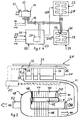
- FIG. 1 schematically shows the backrest 22 and the seat part 24 an air conditioning seat for a vehicle.
- a surface heating element 26 on the back 22 and the Seat part 24 is a surface heating element 26 in a known manner or 27 of an automobile seat heater, each have a line-shaped heating conductor 29 which e.g. B. consists of copper.
- the heating conductors 29 are connected to one Power source (not shown) connected, the by the Heating conductor 29 flowing current by means of a control device serving microprocessor 20 is regulated.
- the microprocessor 20 also controls the temperature and the humidity level of air mass flows Q41 and Q42, the from an air conditioning device 18 of the seat contact surface of the seat part 24 and the backrest 22 are supplied.
- a climate controller 14 connected to an on / off switch 10 and, for example, a six-stage setpoint generator 12 having.
- the seat passenger can use the setpoint generator 12 select the desired temperature (temperature setpoint).
- the temperature setpoint is, for example, a resistance value a potentiometer, a resistance decade or specified another variable resistance value.
- the actual temperature in the area of the seat contact surface of the seat part 24 is used, for example, by an NTC temperature sensor 28 detected and a corresponding temperature signal in the microprocessor 20 entered. Characteristic fields are in the microprocessor filed, by means of which the microprocessor 20 the Air conditioning device 18 and the electrical surface heating elements 26, 27 depending on the initial temperature the seat contact surface of the seat part 24 and / or the backrest 22 regulates.
- Material parameters can be entered in the characteristic curve fields at the same time the climate seat, e.g. the air permeability of the seat cover, the condition of the climate seat between the air conditioning device 18 and the respective seat contact surface, the moisture transport in this area depending of the prevailing partial pressures, the thermal Temperature conductivity etc. are taken into account.
- the structure of the air conditioning device is shown in FIG. 2 the air conditioning of the seat part 24 of a climate seat closer explained.
- the seat part 24 of the air conditioning seat has one for air and water vapor permeable seat contact surface 31 made of fabric or perforated or porous leather on the lower Inside a sheet-like permeable for air and water vapor adjacent electrical heating element 26, e.g. is described in DE 30 40 888 A1.
- On the seat contact surface 31 opposite side is below the electric surface heating element 26 one for air and water vapor permeable intermediate layer 32 made of cushioning material, the Minimum requirements regarding the compressed state Air and water vapor permeability fulfilled, arranged, which rests on a foam padding 34.
- Feed channels 36 are provided which extend from the Bottom to the top of the foam padding 34 extend below the intermediate layer 32.
- a temperature sensor 28 arranged on the underside of the intermediate layer 32.
- a branch line 38 is inserted into the feed channels 36, that with a main line 41 of the air conditioning device 18 is connected to the outflow side of a Air duct 40 connects.
- the supply ducts 36, the branch lines 38 and the main line 41 form an air supply system.
- the air duct 40 is U-shaped in the longitudinal direction.
- On the air inlet side connected to the ambient air of the air duct 40 is a fan blower 50 arranged, with the help of ambient air into the air duct 40th is blown in and flows through the air duct 40.
- a Peltier element Adjacent to the leg of the air duct 40 on the inlet side is a Peltier element between the two legs of the air duct 40 42 arranged, the cooling side of the inlet side Leg and its heating side the outlet side Leg of the air duct 40 faces.
- a heat exchanger 44 is provided through the inlet-side leg of the air duct 40 extends.
- the heat exchangers are designed as finned heat exchangers, in terms of size, flow resistance and heat transfer are optimized.
- wick 48 is provided, which is connected to the heating side of the Peltier element 42 stands.
- a second heat exchanger 46 On the heating side of the Peltier element 42 is a second heat exchanger 46 provided, which is adjacent to the cooling side of the Peltier element 42 by a parallel to the legs extending cooling channel 52 and then in the outlet side Leg of the air duct 40 extends.
- a fan blower 54 At the The inlet side of the cooling duct 52 is a fan blower 54 provided with the help of an air flow Q2 from the environment can be sucked into the cooling channel 52.
- the air conditioning device becomes a through the fan 50 in the air duct 40 Intake air mass flow Q1 through the on the cooling side of the Peltier element 42 arranged first heat exchanger 44 cooled below the dew point so that contained in the air Water is condensed and separated. This water will dissipated via the wick 48 to the heating side of the Peltier element 42, where it evaporates into the ambient air.
- the dehumidified air then flows through the second Heat exchanger 46 by which it is heated, which causes the relative Humidity of the air is further reduced.
- the on this Conditioned air is then passed through the main line 41 and the branch lines 38 into the supply channels 38 blown.
- the seat materials and the air flow are chosen so that the conditioned air with the upper seat structures and with the air between the seat and the seat passenger interact occurs and drying over the water partial pressure drop he follows. After the interaction has taken place, part of the Air back through the foam 34 into the ambient air, while the other part passes the seat passenger.
- the Cooling of the air flow Q1 via the speed of the fan 50 be managed.
- the speed of the Blower 54 is the temperature of the air duct 40th Cooling leaving air mass flow Q4 selectively, as the ambient air drawn into the cooling duct 52 by the fan 54 flows through the second heat exchanger 46 and thus its Temperature decreased.
- the one flowing through the cooling channel 52 Air is released into the environment as air mass flow Q3.
- the temperature of the air mass flow Q4 is therefore directly dependent the speed of the fan 52.
- the electric heating element 26, the blowers 50 and 54 and that Peltier element 42 are connected to the microprocessor 20 and become dependent on this by using the related to the input side of the microprocessor Temperature sensor 28 measured actual temperature and the predetermined Target temperature regulated.
- the air conditioning device by the seat passenger put into operation by switching on / off switch 10 and the corresponding desired temperature on the climate controller has been set by the temperature sensor 28 the initial temperature in the area of the seat contact surface 31 corresponding temperature signal to the microprocessor 20 given.
- control device 20 determines the control device 20 based on the stored Characteristic fields the controlled system of the electrical Heating element 26, the blower 50, 54 and the Peltier element 42.
- the control is carried out in such a way that the microprocessor 20 activates the electric heating element 26 and heats the seat at full power to the desired temperature T set selected on the setpoint device.
- the air conditioning device 18 is switched on and the power of the electric heating element 26 is reduced. Both the electric heating element 26 and the air conditioning device 18 now ensure a uniform temperature control of the seat.
- the air conditioning device 18 additionally ensures dehumidification of the seat contact surface 31 of the seat part 24. Only when the seat part 24 is completely heated is the electric heating element 26 switched off and the temperature of the seat contact surface 31 solely by the air conditioning device 18 by regulating the blowers 50 and 54 and of the Peltier element 42.
- the seat part 24 has a very large heat capacity at a low If the temperature level is displayed, it would switch off too early of the electric heating element 26 to cool down again lead the seat contact surface 31.
- the seat contact surface 31 of the seat part 24 Commissioning of the air conditioning device by the sun is heated, its temperature can be 60 ° C and more. In this case, by blowing cool, dry air into the seat part by the air conditioning device 18 Seat contact surface 31 of the seat part 24 cooled quickly.
- the temperature is briefly cooled to such an extent that the target temperature T set, which is set by means of the target value transmitter 12, is significantly below the target value for a short time, for example to approximately 28 ° C.
- the short-term cooling effect has the advantage that the Seat passenger the effectiveness of the air conditioning device notices. Since the duration of the clear cooling is very short, a health risk for the seated passenger is avoided.
- the microprocessor controls this "cool-down effect" 20 the air conditioning device 18 so that the seat temperature, i.e. the actual temperature measured by the temperature sensor, corresponds to the set temperature set on the controller.
- the air conditioning device performs during the entire operating time 18 the microclimate between the seat contact surface and seat passenger moisture.
- the air conditioning device 18 In moderate ambient conditions, i.e. when the actual temperature measured by the temperature sensor 28 when the air conditioning device is activated is within the temperature range specified by the setpoint generator 12, the air conditioning device 18 is activated such that it only removes the moisture in the microclimate and the seat temperature in the range of predetermined target temperature T set regulates.
- the air conditioning of the back 22 of the air conditioning seat can be adjusted to the done the same way.
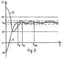
- the control curves for a very cold and very warm climate seat are shown in FIG. 3.
- the time t is plotted along the abscissa and the temperature T of the climate seat in the region of the seat contact surface 31.
- T Set is the target temperature that can be predetermined by the target value transmitter 12.
- the target temperature can be set between approx. 32 ° C and 41 ° C. This temperature range is medically harmless for the human body.
- Curve 1 in Fig. 3 shows the heating of the seat at an initial temperature of -20 ° C.
- the time t H when the seat is heated to the desired temperature, only the electrical surface heating element is effective and is operated at full power.
- the seat is tempered in the range of the target temperature T set with the aid of the electrical heating element and the air conditioning device. From time t HK only the air conditioning device for dehumidifying and tempering the seat is effective.
- Curve 2 shows the temperature of the seat at a very high starting temperature of approx. 60 ° C.
- the temperature of the seat is quickly lowered to a temperature of approximately 28 ° C. in order to obtain the "cool-down effect" mentioned above.
- the seat is then brought to the desired temperature T set only by means of the air conditioning device 18 up to the time t K.
- the temperature and the dehumidification of the seat are regulated by means of the air conditioning device 18 such that they remain in the range of the target temperature T set .
Landscapes
- Engineering & Computer Science (AREA)
- Mechanical Engineering (AREA)
- Aviation & Aerospace Engineering (AREA)
- Transportation (AREA)
- General Engineering & Computer Science (AREA)
- Air-Conditioning For Vehicles (AREA)
- Chair Legs, Seat Parts, And Backrests (AREA)
Claims (12)
- Siège climatisé comportantau moins une surface de contact du siège (31) dont le côté externe est orienté vers une partie d'un passager du siège,un dispositif de conditionnement de l'air (18), qui amène de l'air à la zone du côté interne de la surface de contact du siège (31), dont la pression partielle de vapeur d'eau est plus faible que dans le microclimat situé entre la surface de contact du siège (31) et le passager du siège,un élément de chauffage électrique (24) disposé dans la zone du côté interne de la surface de contact du siège (31) visant à chauffer la surface de contact du siège (31),un dispositif palpeur de température (28) pour détecter la température dans la zone de la surface de contact du siège (31), etun dispositif de réglage (20) qui est en liaison non seulement avec le dispositif de conditionnement de l'air (18) mais aussi avec l'élément de chauffage électrique (24) et règle ceux-ci, en fonction de la température mesurée par le dispositif palpeur de température (28), suivant une valeur prescrite de température définie à l'avance, caractérisé en ce quele dispositif de conditionnement de l'air (18) présente un élément Peltier (42) avec un premier échangeur thermique (44) sur son côté de refroidissement et un deuxième échangeur thermique (46) sur son côté de chauffage, le premier (44) et le deuxième échangeur thermique (46) s'étendant dans un canal d'air (40), qui est en liaison, dans le sens d'écoulement après le deuxième échangeur thermique (46), avec un système d'adduction d'air (41, 38, 36) qui amène l'air traversant le deuxième échangeur thermique (46) à la zone du côté interne de la surface de contact du siège (31).
- Siège climatisé selon la revendication 1, caractérisé en ce que la température de l'air amené par le dispositif de conditionnement de l'air (18) peut être réglée au moyen du dispositif de réglage (20).
- Siège climatisé selon la revendication 1, caractérisé en ce que non seulement la température mais aussi l'humidité de l'air amené par le dispositif de conditionnement de l'air (18) peut être réglée au moyen du dispositif de réglage (20).
- Siège climatisé selon les revendications 1 à 3, caractérisé en ce que le dispositif de réglage (20) est formé par un microprocesseur, dans lequel sont enregistrés des réseaux de caractéristiques pour le réglage du dispositif de conditionnement de l'air (18) et de l'élément de chauffage électrique (24) en fonction de la température mesurée.
- Siège climatisé selon la revendication 4, caractérisé en ce que dans les réseaux de caractéristiques sont pris en considération des paramètres de matériaux pour la zone située entre la surface de contact du siège (31) et le dispositif de conditionnement de l'air (18).
- Siège climatisé selon la revendication 1, caractérisé en ce que le deuxième échangeur thermique (46) s'étend dans un canal de refroidissement (52) pouvant être traversé par de l'air de refroidissement.
- Siège climatisé selon la revendication 1, caractérisé en ce que dans le canal d'air (40) et dans le canal de refroidissement (52) est disposé à chaque fois une soufflante (50, 54), dont la vitesse de rotation peut être réglée par le dispositif de réglage (20).
- Siège climatisé selon la revendication 1, caractérisé en ce que dans le canal d'air (40) après le premier échangeur thermique (44) est disposée une mèche (48) qui s'étend vers le côté de chauffage de l'élément Peltier (42).
- Procédé de réglage de la température du siège climatisé selon la revendication 1, dans lequel avec une température initiale élevée de la zone de la surface de contact du siègele dispositif de conditionnement de l'air est actionné de telle manière que l'air conditionné, amené par celui-ci à la zone de la surface de contact du siège, refroidit rapidement et pour peu de temps la température de la surface de contact du siège à une température qui se situe nettement au-dessous d'une température prescrite définie à l'avance, etensuite le dispositif de conditionnement de l'air est actionné de telle sorte que la température prescrite est atteinte et sensiblement maintenue grâce à l'air conditionné amené par ledit dispositif à la zone de la surface de contact du siège.
- Procédé selon la revendication 9, caractérisé en ce que l'air est refroidi de façon répétée et pour peu de temps à une température, qui se situe nettement au-dessous de la température prescrite définie à l'avance.
- Procédé selon la revendication 10, caractérisé en ce que la surface de contact du dossier et celle de la surface de siège sont refroidies alternativement.
- Procédé de réglage de la température du siège climatisé selon la revendication 1, dans lequel à une température initiale basse de la zone de la surface de contact du siègel'élément de chauffage électrique est actionné à plein régime, jusqu'à ce qu'une température prescrite soit atteinte,après obtention de la température prescrite, le dispositif de conditionnement de l'air est en outre actionné et le régime de l'élément de chauffage électrique est réduit, la température prescrite étant ainsi sensiblement maintenue,après chauffage intégral parfait de la surface de contact du siège et des zones l'entourant, l'élément de chauffage électrique est arrêté et le dispositif de conditionnement de l'air est actionné de sorte que la température prescrite est essentiellement maintenue grâce à l'air conditionné amené par ledit dispositif dans la zone de la surface de contact du siège.
Applications Claiming Priority (5)
| Application Number | Priority Date | Filing Date | Title |
|---|---|---|---|
| DE19504716 | 1995-02-14 | ||
| DE19504716 | 1995-02-14 | ||
| DE19548527 | 1995-12-22 | ||
| DE19548527 | 1995-12-22 | ||
| PCT/EP1996/000638 WO1996025301A1 (fr) | 1995-02-14 | 1996-02-14 | Siege climatise |
Publications (2)
| Publication Number | Publication Date |
|---|---|
| EP0809576A1 EP0809576A1 (fr) | 1997-12-03 |
| EP0809576B1 true EP0809576B1 (fr) | 1999-05-06 |
Family
ID=26012399
Family Applications (1)
| Application Number | Title | Priority Date | Filing Date |
|---|---|---|---|
| EP96904780A Expired - Lifetime EP0809576B1 (fr) | 1995-02-14 | 1996-02-14 | Siege climatise |
Country Status (8)
| Country | Link |
|---|---|
| US (1) | US5921314A (fr) |
| EP (1) | EP0809576B1 (fr) |
| JP (1) | JP3064016B2 (fr) |
| KR (1) | KR100305560B1 (fr) |
| CA (1) | CA2211943A1 (fr) |
| DE (1) | DE59601826D1 (fr) |
| ES (1) | ES2133942T3 (fr) |
| WO (1) | WO1996025301A1 (fr) |
Cited By (9)
| Publication number | Priority date | Publication date | Assignee | Title |
|---|---|---|---|---|
| DE19953385A1 (de) * | 1999-11-06 | 2001-05-10 | Volkswagen Ag | Verfahren und Vorrichtung zur Steuerung einer Einrichtung zur Klimatisierung eines Fahrzeugsitzes sowie Bedieneinrichtung dafür |
| DE10210149A1 (de) * | 2002-03-07 | 2003-09-18 | Volkswagen Ag | Verfahren und Einrichtung zur Beurteilung von Sitzheizungs- und/oder Belüftungssystemen |
| DE102004007859A1 (de) * | 2004-02-17 | 2005-09-08 | W.E.T. Automotive Systems Ag | Temperiervorrichtung für Fahrzeugsitze |
| US7735932B2 (en) | 2005-08-19 | 2010-06-15 | W.E.T. Automotive Systems Ag | Automotive vehicle seat insert |
| US7781704B2 (en) | 2003-09-25 | 2010-08-24 | W.E.T. Automotive Systems Ag | Control system for operating automotive vehicle components |
| US7918498B2 (en) | 2003-12-01 | 2011-04-05 | W.E.T. Automotive Systems Ag | Valve layer for a seat |
| US8167368B2 (en) | 2009-02-18 | 2012-05-01 | W.E.T. Automotive System Ag | Air conditioning device for vehicle seats |
| US8777320B2 (en) | 2008-12-21 | 2014-07-15 | W.E.T. Automotive Systems Ag | Ventilation system |
| US9085255B2 (en) | 2008-04-08 | 2015-07-21 | Gentherm Gmbh | Ventilation means |
Families Citing this family (112)
| Publication number | Priority date | Publication date | Assignee | Title |
|---|---|---|---|---|
| DE19703516C1 (de) * | 1997-01-31 | 1998-05-07 | Daimler Benz Ag | Fahrzeugsitz |
| JP3637395B2 (ja) * | 1997-04-28 | 2005-04-13 | 本田技研工業株式会社 | 車両の空調装置とシート用加熱冷却装置 |
| DE19752135A1 (de) * | 1997-11-25 | 1999-06-17 | Bosch Gmbh Robert | Verfahren zur Heizstromregelung und Sitzheizungsregelschaltung |
| US6105667A (en) * | 1998-03-12 | 2000-08-22 | Denso Corporation | Air conditioning apparatus for vehicle seat |
| US6119463A (en) | 1998-05-12 | 2000-09-19 | Amerigon | Thermoelectric heat exchanger |
| DE19920451C2 (de) * | 1998-05-18 | 2003-05-22 | Wet Automotive Systems Ag | Belüftbarer und beheizbarer Sitz |
| DE19851979C2 (de) * | 1998-11-11 | 2000-08-31 | Daimler Chrysler Ag | Temperaturfühler für einen klimatisierten Fahrzeugsitz |
| US6273810B1 (en) | 1999-09-10 | 2001-08-14 | Mccord Winn Textron Inc. | Inflatable air cell having combined pneumatically adjusted occupant support and thermal conditioning |
| AU6370799A (en) * | 1999-10-26 | 2001-05-08 | Cheol Hyeon Choi | Coolness and warmth device for car seat using peltier's effect |
| US8986085B2 (en) | 1999-11-06 | 2015-03-24 | Volkswagen Ag | Method and device for controlling equipment for air conditioning a vehicle seat, and control equipment therefor |
| DE10002286B4 (de) * | 2000-01-20 | 2009-06-18 | Volkswagen Ag | Vorrichtung zur Steuerung einer Einrichtung zur Klimatisierung eines Fahrzeugsitzes |
| DE10026656A1 (de) * | 2000-05-29 | 2001-12-13 | Siemens Ag | Verfahren und Vorrichtung zum Klimatisieren eines Sitzes eines Kraftfahrzeugs |
| SE0002690L (sv) * | 2000-07-19 | 2002-01-20 | Kongsberg Automotive Ab | Anordning och förfarande för temperaturreglering och ventilering av ett säte |
| US6353207B1 (en) | 2000-08-17 | 2002-03-05 | Ctex Seat Comfort Ltd. | Expandable chamber having combined occupant support and heating |
| US6629724B2 (en) | 2001-01-05 | 2003-10-07 | Johnson Controls Technology Company | Ventilated seat |
| US7040710B2 (en) | 2001-01-05 | 2006-05-09 | Johnson Controls Technology Company | Ventilated seat |
| US6786541B2 (en) | 2001-01-05 | 2004-09-07 | Johnson Controls Technology Company | Air distribution system for ventilated seat |
| DE20112473U1 (de) * | 2001-07-28 | 2002-12-19 | Johnson Controls Gmbh | Klimatisiertes Polsterteil für einen Fahrzeugsitz |
| US20090184107A1 (en) * | 2001-09-03 | 2009-07-23 | Michael Weiss | Heating element with stranded contact |
| US6552442B2 (en) * | 2001-09-27 | 2003-04-22 | Ford Global Technologies, Inc. | Method and apparatus for controlling the temperature of a vehicular seat |
| DE20120516U1 (de) * | 2001-12-19 | 2003-04-30 | Johnson Controls Gmbh | Belüftungssystem für ein Polsterteil |
| DE10206114C1 (de) * | 2002-02-13 | 2003-05-15 | Wet Automotive Systems Ag | Klimatisierungsvorrichtung mit Bedieneinrichtung |
| KR20020062240A (ko) * | 2002-05-21 | 2002-07-25 | 박재현 | 자동차 시트 냉난방 장치 |
| KR20040001385A (ko) * | 2002-06-28 | 2004-01-07 | 주식회사 광진산업 | 차량용 시트의 냉 온방 겸용 장치 |
| US6893086B2 (en) * | 2002-07-03 | 2005-05-17 | W.E.T. Automotive Systems Ltd. | Automotive vehicle seat insert |
| US7306283B2 (en) | 2002-11-21 | 2007-12-11 | W.E.T. Automotive Systems Ag | Heater for an automotive vehicle and method of forming same |
| ES2264743T5 (es) * | 2003-04-02 | 2012-05-16 | Catem Gmbh & Co.Kg | Asiento de automóvil y módulo de ventilador para este asiento de automóvil |
| US7477969B2 (en) | 2003-10-02 | 2009-01-13 | W.E.T. Automotive Systems Ag | Temperature conditioned assembly having a controller in communication with a temperature sensor |
| US7425034B2 (en) * | 2003-10-17 | 2008-09-16 | W.E.T. Automotive Systems Ag | Automotive vehicle seat having a comfort system |
| WO2005037601A2 (fr) | 2003-10-17 | 2005-04-28 | W.E.T.Automotive Systems Ag. | Garniture interne pour siege de vehicule automobile |
| DE112005001105A5 (de) * | 2004-03-08 | 2007-05-24 | W.E.T. Automotive Systems Ag | Flächiges Heizelement |
| WO2005084494A1 (fr) * | 2004-03-09 | 2005-09-15 | Matsushita Electric Industrial Co., Ltd. | Siége à air conditionné et système de conditionnement d'air utilisant celui-ci |
| US7587901B2 (en) | 2004-12-20 | 2009-09-15 | Amerigon Incorporated | Control system for thermal module in vehicle |
| JP4926078B2 (ja) * | 2005-02-07 | 2012-05-09 | エル アンド ピー プロパティ マネジメント カンパニー | 自動車用換気、温度調節および人間工学的コンフォート・システム |
| US7827805B2 (en) * | 2005-03-23 | 2010-11-09 | Amerigon Incorporated | Seat climate control system |
| US7743614B2 (en) | 2005-04-08 | 2010-06-29 | Bsst Llc | Thermoelectric-based heating and cooling system |
| US20060254284A1 (en) * | 2005-05-11 | 2006-11-16 | Yuji Ito | Seat air conditioning unit |
| DE102006052935A1 (de) * | 2005-11-10 | 2007-06-14 | W.E.T. Automotive Systems Ag | Fahrzeugsitz mit Polsterschicht |
| WO2007065424A2 (fr) * | 2005-12-11 | 2007-06-14 | W.E.T. Automotive Systems Ag | Element chauffant plat |
| US8104295B2 (en) | 2006-01-30 | 2012-01-31 | Amerigon Incorporated | Cooling system for container in a vehicle |
| US20070200398A1 (en) * | 2006-02-28 | 2007-08-30 | Scott Richard Wolas | Climate controlled seat |
| JP2007240046A (ja) * | 2006-03-07 | 2007-09-20 | Denso Corp | 空調装置 |
| US8539624B2 (en) | 2006-05-31 | 2013-09-24 | Gentherm Incorporated | Structure based fluid distribution system |
| US8222511B2 (en) * | 2006-08-03 | 2012-07-17 | Gentherm | Thermoelectric device |
| KR100820029B1 (ko) * | 2006-08-24 | 2008-04-07 | 정상호 | 자동차 시트의 온도 조절 장치 |
| US20080087316A1 (en) | 2006-10-12 | 2008-04-17 | Masa Inaba | Thermoelectric device with internal sensor |
| ES2399148T3 (es) | 2006-10-13 | 2013-03-26 | Gentherm Incorporated | Cama con aire acondicionado |
| KR100770106B1 (ko) * | 2006-10-24 | 2007-10-24 | 삼성에스디아이 주식회사 | 리튬 이차 전지 |
| EP2102564B1 (fr) | 2007-01-10 | 2015-09-02 | Gentherm Incorporated | Dispositif thermoélectrique |
| US8143554B2 (en) * | 2007-03-16 | 2012-03-27 | Amerigon Incorporated | Air warmer |
| US7823967B2 (en) * | 2007-03-26 | 2010-11-02 | Emteq, Inc. | Heater system for an aircraft seat |
| CN101720414B (zh) | 2007-05-25 | 2015-01-21 | Bsst有限责任公司 | 分配式热电加热和冷却的系统和方法 |
| US20090033130A1 (en) * | 2007-07-02 | 2009-02-05 | David Marquette | Fluid delivery systems for climate controlled seats |
| JP2010534821A (ja) * | 2007-07-23 | 2010-11-11 | アメリゴン インコーポレイティド | 半径方向熱電装置アセンブリ |
| US9105809B2 (en) | 2007-07-23 | 2015-08-11 | Gentherm Incorporated | Segmented thermoelectric device |
| WO2009036077A1 (fr) | 2007-09-10 | 2009-03-19 | Amerigon, Inc. | Systèmes de commande de fonctionnement pour ensembles lit ou siège ventilé |
| US9125497B2 (en) | 2007-10-15 | 2015-09-08 | Gentherm Incorporated | Climate controlled bed assembly with intermediate layer |
| DE112008002682A5 (de) | 2007-10-18 | 2010-07-01 | W.E.T. Automotive Systems Ag | Elektrische Leiteinrichtung |
| WO2009056112A1 (fr) * | 2007-10-29 | 2009-05-07 | W.E.T. Automotive Systems Ag | Dispositif de climatisation pour sièges |
| JP2011506178A (ja) * | 2007-12-10 | 2011-03-03 | ヴィー・エー・テー・オートモーティヴ・システムス・アクチェンゲゼルシャフト | 改良された空調モジュールおよび方法 |
| KR20170064568A (ko) | 2008-02-01 | 2017-06-09 | 젠썸 인코포레이티드 | 열전 소자용 응결 센서 및 습도 센서 |
| US20090218855A1 (en) * | 2008-02-26 | 2009-09-03 | Amerigon Incorporated | Climate control systems and devices for a seating assembly |
| AU2009270757B2 (en) | 2008-07-18 | 2016-05-12 | Gentherm Incorporated | Climate controlled bed assembly |
| US8575518B2 (en) * | 2009-01-28 | 2013-11-05 | Gentherm Incorporated | Convective heater |
| DE102009030491A1 (de) | 2009-03-18 | 2010-09-23 | W.E.T. Automotive Systems Ag | Klimatisierungseinrichtung für einen klimatisierten Gegenstand in einem Fahrzeuginnenraum |
| US8893329B2 (en) | 2009-05-06 | 2014-11-25 | Gentherm Incorporated | Control schemes and features for climate-controlled beds |
| CN102576232B (zh) | 2009-05-18 | 2015-05-06 | Bsst有限责任公司 | 带有热电装置的温度控制系统 |
| US8332975B2 (en) | 2009-08-31 | 2012-12-18 | Gentherm Incorporated | Climate-controlled topper member for medical beds |
| DE102009056044A1 (de) * | 2009-11-27 | 2011-06-09 | GM Global Technology Operations LLC, ( n. d. Ges. d. Staates Delaware ), Detroit | Klimaeinrichtung für ein Kraftfahrzeug |
| DE102009059995A1 (de) * | 2009-12-21 | 2011-06-22 | W.E.T. Automotive Systems AG, 85235 | Elektrische Heizeinrichtung |
| DE102011014516A1 (de) | 2010-04-06 | 2012-05-10 | W.E.T. Automotive Systems Ag | Multifunktionsprodukt |
| RU2442934C2 (ru) * | 2010-05-21 | 2012-02-20 | Олег Савельевич Кочетов | Способ оценки комфортности рабочей зоны по параметрам микроклимата |
| US8544942B2 (en) | 2010-05-27 | 2013-10-01 | W.E.T. Automotive Systems, Ltd. | Heater for an automotive vehicle and method of forming same |
| EP3210586B1 (fr) * | 2010-07-09 | 2019-08-28 | Hill-Rom Services, Inc. | Dispositif de fixation pour un réservoir de fluide sur des systèmes de support de patient |
| US9222685B2 (en) | 2010-07-15 | 2015-12-29 | Hill-Rom Services, Inc. | Method and system for controlling evaporative and heat withdrawal performance of an occupant support surface |
| DE102011105675A1 (de) | 2010-07-15 | 2012-01-19 | W.E.T. Automotive Systems Ag | Elektrische Leitung |
| DE102011114949A1 (de) | 2010-10-19 | 2012-04-19 | W.E.T. Automotive Systems Ag | Elektrischer Leiter |
| US9121414B2 (en) | 2010-11-05 | 2015-09-01 | Gentherm Incorporated | Low-profile blowers and methods |
| DE102012000977A1 (de) | 2011-04-06 | 2012-10-11 | W.E.T. Automotive Systems Ag | Heizeinrichtung für komplex geformte Oberflächen |
| FR2975509B1 (fr) * | 2011-05-20 | 2013-06-07 | Renault Sa | Procede et systeme correspondant de commande de la temperature d'un siege d'un vehicule automobile |
| DE102012014678A1 (de) | 2011-08-19 | 2013-02-21 | W.E.T. Automotive Systems Ag | Heizeinrichtung |
| DE102011121979A1 (de) | 2011-09-14 | 2012-11-22 | W.E.T. Automotive Systems Ag | Temperier-Einrichtung |
| US20130068748A1 (en) * | 2011-09-21 | 2013-03-21 | W.E.T. Automotive Systems, Ltd. | Method and apparatus for providing heat to a region around a hole |
| US9685599B2 (en) | 2011-10-07 | 2017-06-20 | Gentherm Incorporated | Method and system for controlling an operation of a thermoelectric device |
| DE202011110107U1 (de) | 2011-11-17 | 2013-02-19 | W.E.T. Automotive Systems Ag | Temperier-Einrichtung |
| DE102012020516A1 (de) | 2011-12-09 | 2013-06-13 | W.E.T. Automotive Systems Ag | Temperier-Einrichtung für eine elektrochemische Spannungsquelle |
| DE102011121980A1 (de) | 2011-12-26 | 2013-06-27 | W.E.T. Automotive Systems Ag | Luftfördereinrichtung |
| US10201039B2 (en) | 2012-01-20 | 2019-02-05 | Gentherm Gmbh | Felt heater and method of making |
| US9989267B2 (en) | 2012-02-10 | 2018-06-05 | Gentherm Incorporated | Moisture abatement in heating operation of climate controlled systems |
| DE202013003491U1 (de) | 2012-06-18 | 2013-09-20 | W.E.T. Automotive Systems Ag | Flächengebilde mit elektrischer Funktion |
| US9451723B2 (en) | 2012-07-06 | 2016-09-20 | Gentherm Incorporated | System and method for thermoelectrically cooling inductive charging assemblies |
| DE102012017047A1 (de) | 2012-08-29 | 2014-03-06 | W.E.T. Automotive Systems Ag | Elektrische Heizeinrichtung |
| DE102012024903A1 (de) | 2012-12-20 | 2014-06-26 | W.E.T. Automotive Systems Ag | Flächengebilde mit elektrischen Funktionselementen |
| US9662962B2 (en) | 2013-11-05 | 2017-05-30 | Gentherm Incorporated | Vehicle headliner assembly for zonal comfort |
| WO2015085150A1 (fr) | 2013-12-05 | 2015-06-11 | Gentherm Incorporated | Systèmes et procédés pour sièges climatisés |
| DE102014000313A1 (de) * | 2014-01-10 | 2015-07-16 | Audi Ag | Vorrichtung zum Abgeben eines Duftstoffs und Kraftfahrzeug mit einer derartigen Vorrichtung |
| KR102051617B1 (ko) | 2014-02-14 | 2019-12-03 | 젠썸 인코포레이티드 | 전도식 대류식 기온 제어 시트 |
| US10160356B2 (en) | 2014-05-09 | 2018-12-25 | Gentherm Incorporated | Climate control assembly |
| US11639816B2 (en) | 2014-11-14 | 2023-05-02 | Gentherm Incorporated | Heating and cooling technologies including temperature regulating pad wrap and technologies with liquid system |
| EP3218942B1 (fr) | 2014-11-14 | 2020-02-26 | Charles J. Cauchy | Technologies de chauffage et de refroidissement |
| US11857004B2 (en) | 2014-11-14 | 2024-01-02 | Gentherm Incorporated | Heating and cooling technologies |
| DE112015005666T5 (de) | 2014-12-19 | 2017-09-14 | Gentherm Incorporated | Thermische Konditionierungssysteme und -verfahren für Fahrzeugbereiche |
| US10625566B2 (en) | 2015-10-14 | 2020-04-21 | Gentherm Incorporated | Systems and methods for controlling thermal conditioning of vehicle regions |
| WO2019080957A1 (fr) * | 2017-10-27 | 2019-05-02 | Gentherm Gmbh | Dispositif de thermorégulation de surface |
| DE102017220770A1 (de) | 2017-11-21 | 2019-05-23 | Volkswagen Aktiengesellschaft | Klimatisierungssystem eines Fahrzeugsitzes mit komfortoptimierter Betriebsweise durch bedarfsgerechte Umschaltung des Sitzbelüftungssystems |
| DE102018204947A1 (de) * | 2018-03-29 | 2019-10-02 | Volkswagen Aktiengesellschaft | Fahrzeugsitz mit einer komfortoptimierten Sitzheizungsregelung mit Aufheizszenarien |
| JP7059783B2 (ja) * | 2018-05-07 | 2022-04-26 | 株式会社デンソー | 車室用空調システム |
| US20200035898A1 (en) | 2018-07-30 | 2020-01-30 | Gentherm Incorporated | Thermoelectric device having circuitry that facilitates manufacture |
| US20200253387A1 (en) * | 2019-02-08 | 2020-08-13 | Hill-Rom Services, Inc. | Method for optimizing skin cooling level of an occupant support surface |
| US11152557B2 (en) | 2019-02-20 | 2021-10-19 | Gentherm Incorporated | Thermoelectric module with integrated printed circuit board |
| DE102019212804A1 (de) * | 2019-08-27 | 2021-03-04 | Volkswagen Aktiengesellschaft | Fahrzeugsitz mit einer komfortoptimierten Sitzheizungs- und Sitzbelüftungsregelung |
| DE102019212803A1 (de) * | 2019-08-27 | 2021-03-04 | Volkswagen Aktiengesellschaft | Komponente, insbesondere Fahrzeugsitz oder Bekleidungsstück mit einer thermischen Komfortregelung, die mit einer Massageeinrichtung gekoppelt ist |
Family Cites Families (7)
| Publication number | Priority date | Publication date | Assignee | Title |
|---|---|---|---|---|
| JPS6042115A (ja) * | 1983-08-17 | 1985-03-06 | Takagi Kagaku Kenkyusho:Kk | 車両用座席の空調装置 |
| US5117638A (en) * | 1991-03-14 | 1992-06-02 | Steve Feher | Selectively cooled or heated seat construction and apparatus for providing temperature conditioned fluid and method therefor |
| DE4112631C1 (en) * | 1991-04-18 | 1992-04-30 | Keiper Recaro Gmbh & Co, 5630 Remscheid, De | Motor vehicle seat with moisture removal inset - incorporating air channel at rear of backrest with air dryer |
| JP3301109B2 (ja) * | 1991-11-14 | 2002-07-15 | 株式会社デンソー | 座席用空調装置 |
| JPH0626600U (ja) * | 1992-09-09 | 1994-04-12 | 信博 松本 | 車のシートエアコン |
| US5524439A (en) * | 1993-11-22 | 1996-06-11 | Amerigon, Inc. | Variable temperature seat climate control system |
| US5613730A (en) * | 1995-03-29 | 1997-03-25 | Buie; Dan | Temperature controlled seat cover assembly |
-
1996
- 1996-02-14 WO PCT/EP1996/000638 patent/WO1996025301A1/fr active IP Right Grant
- 1996-02-14 JP JP8524664A patent/JP3064016B2/ja not_active Expired - Fee Related
- 1996-02-14 US US08/894,316 patent/US5921314A/en not_active Expired - Fee Related
- 1996-02-14 EP EP96904780A patent/EP0809576B1/fr not_active Expired - Lifetime
- 1996-02-14 DE DE59601826T patent/DE59601826D1/de not_active Expired - Fee Related
- 1996-02-14 KR KR1019970705554A patent/KR100305560B1/ko not_active IP Right Cessation
- 1996-02-14 ES ES96904780T patent/ES2133942T3/es not_active Expired - Lifetime
- 1996-02-14 CA CA002211943A patent/CA2211943A1/fr not_active Abandoned
Cited By (17)
| Publication number | Priority date | Publication date | Assignee | Title |
|---|---|---|---|---|
| DE19953385A1 (de) * | 1999-11-06 | 2001-05-10 | Volkswagen Ag | Verfahren und Vorrichtung zur Steuerung einer Einrichtung zur Klimatisierung eines Fahrzeugsitzes sowie Bedieneinrichtung dafür |
| DE10210149A1 (de) * | 2002-03-07 | 2003-09-18 | Volkswagen Ag | Verfahren und Einrichtung zur Beurteilung von Sitzheizungs- und/oder Belüftungssystemen |
| US8309892B2 (en) | 2003-09-25 | 2012-11-13 | W.E.T. Automotive System, Ltd | Control system for operating automotive vehicle components |
| US7781704B2 (en) | 2003-09-25 | 2010-08-24 | W.E.T. Automotive Systems Ag | Control system for operating automotive vehicle components |
| US7918498B2 (en) | 2003-12-01 | 2011-04-05 | W.E.T. Automotive Systems Ag | Valve layer for a seat |
| US8235462B2 (en) | 2003-12-01 | 2012-08-07 | W.E.T. Automotive Systems, Ltd. | Valve layer for a seat |
| DE102004007859A1 (de) * | 2004-02-17 | 2005-09-08 | W.E.T. Automotive Systems Ag | Temperiervorrichtung für Fahrzeugsitze |
| DE102004007859B4 (de) * | 2004-02-17 | 2007-02-08 | W.E.T. Automotive Systems Ag | Temperiervorrichtung für Fahrzeugsitze |
| US8162391B2 (en) | 2005-08-19 | 2012-04-24 | W.E.T. Automotive Systems Ag | Automotive vehicle seat insert |
| US7971931B2 (en) | 2005-08-19 | 2011-07-05 | W.E.T. Automotive Systems Ag | Automotive vehicle seat insert |
| US7735932B2 (en) | 2005-08-19 | 2010-06-15 | W.E.T. Automotive Systems Ag | Automotive vehicle seat insert |
| US8360517B2 (en) | 2005-08-19 | 2013-01-29 | W.E.T. Automotive Systems, Ag. | Automotive vehicle seat insert |
| US9440567B2 (en) | 2005-08-19 | 2016-09-13 | Gentherm Gmbh | Automotive vehicle seat insert |
| US9085255B2 (en) | 2008-04-08 | 2015-07-21 | Gentherm Gmbh | Ventilation means |
| US8777320B2 (en) | 2008-12-21 | 2014-07-15 | W.E.T. Automotive Systems Ag | Ventilation system |
| US9415712B2 (en) | 2008-12-21 | 2016-08-16 | Gentherm Gmbh | Ventilation system |
| US8167368B2 (en) | 2009-02-18 | 2012-05-01 | W.E.T. Automotive System Ag | Air conditioning device for vehicle seats |
Also Published As
| Publication number | Publication date |
|---|---|
| WO1996025301A1 (fr) | 1996-08-22 |
| KR100305560B1 (ko) | 2001-11-22 |
| DE59601826D1 (de) | 1999-06-10 |
| US5921314A (en) | 1999-07-13 |
| JPH10503733A (ja) | 1998-04-07 |
| EP0809576A1 (fr) | 1997-12-03 |
| KR19980702159A (ko) | 1998-07-15 |
| ES2133942T3 (es) | 1999-09-16 |
| JP3064016B2 (ja) | 2000-07-12 |
| CA2211943A1 (fr) | 1996-08-22 |
Similar Documents
| Publication | Publication Date | Title |
|---|---|---|
| EP0809576B1 (fr) | Siege climatise | |
| DE10105094B4 (de) | Fahrzeugsitz | |
| DE60130989T2 (de) | Sitz mit temperaturregelung und belueftung, und sicherheitssystem für ein fahrzeug | |
| DE10316275B4 (de) | Fahrzeugsitz | |
| DE10238552A1 (de) | System und Verfahren für die Klimaregelung in Fahrzeugen | |
| EP1888368B1 (fr) | Siege de vehicule comportant une couche de ventilation sous un revetement de surface | |
| DE19920451C2 (de) | Belüftbarer und beheizbarer Sitz | |
| WO1996025301B1 (fr) | Siege climatise | |
| DE60112473T2 (de) | Belüfteter fahrzeugsitz | |
| DE102017003550B4 (de) | Verfahren zum Betrieb eines Heizungs-, Lüftungs- und/oder Klimatisierungssystems und Heizungs-, Lüftungs- und/oder Klimatisierungssystem | |
| DE102010017053B4 (de) | Wärm- und Kühlvorrichtung für Fahrzeugsitz | |
| EP0805056A2 (fr) | Conditionnement d'air pour véhicule avec dispositif pour diriger l'air, réglable en fonction du rayonnement solaire | |
| DE10316732B4 (de) | Verfahren und Vorrichtung zur Regelung von Klima-/Belüftungssitzen in Abhängigkeit der Sitz- und Fahrzeuginnenraumtemperatur | |
| DE102009043687A1 (de) | Kraftfahrzeugklimaanlage | |
| DE19602805B4 (de) | Verfahren zum Steuern einer Fahrzeug-Klimaanlage | |
| DE1037684B (de) | Verfahren zur Regelung des Luftklimas in Raeumen | |
| DE10026656A1 (de) | Verfahren und Vorrichtung zum Klimatisieren eines Sitzes eines Kraftfahrzeugs | |
| EP3713788B1 (fr) | Système de climatisation d'un siège de véhicule ayant un fonctionnement optimisé en matière de confort en commutant le système de ventilation du siège selon les besoins | |
| DE4308119C2 (de) | Verfahren und Vorrichtung zur Beeinflussung des Klimas für Insassen eines Kraftfahrzeugs | |
| DE4143101C2 (de) | Klimaanlage für ein Kraftfahrzeug | |
| DE102009013258A1 (de) | Polster für einen Fahrzeugsitz | |
| EP1757476B1 (fr) | Procédé et dispositif de contrôle d'un système de climatisation d'habitacle de véhicule | |
| EP1270287B1 (fr) | Procédé de réglage de la température intérieure d'un habitacle de véhicule et dispositif de chauffage ou de climatisation pour véhicule | |
| DE102007033222B4 (de) | Verfahren und Vorrichtung zum Steuern oder Regeln einer Sitzheizung | |
| DE10350557B4 (de) | Fahrzeugsitz |
Legal Events
| Date | Code | Title | Description |
|---|---|---|---|
| PUAI | Public reference made under article 153(3) epc to a published international application that has entered the european phase |
Free format text: ORIGINAL CODE: 0009012 |
|
| 17P | Request for examination filed |
Effective date: 19970710 |
|
| AK | Designated contracting states |
Kind code of ref document: A1 Designated state(s): DE ES FR GB IT SE |
|
| GRAG | Despatch of communication of intention to grant |
Free format text: ORIGINAL CODE: EPIDOS AGRA |
|
| 17Q | First examination report despatched |
Effective date: 19980204 |
|
| GRAG | Despatch of communication of intention to grant |
Free format text: ORIGINAL CODE: EPIDOS AGRA |
|
| GRAH | Despatch of communication of intention to grant a patent |
Free format text: ORIGINAL CODE: EPIDOS IGRA |
|
| GRAH | Despatch of communication of intention to grant a patent |
Free format text: ORIGINAL CODE: EPIDOS IGRA |
|
| RAP1 | Party data changed (applicant data changed or rights of an application transferred) |
Owner name: W.E.T. AUTOMOTIVE SYSTEMS AG |
|
| GRAA | (expected) grant |
Free format text: ORIGINAL CODE: 0009210 |
|
| AK | Designated contracting states |
Kind code of ref document: B1 Designated state(s): DE ES FR GB IT SE |
|
| REF | Corresponds to: |
Ref document number: 59601826 Country of ref document: DE Date of ref document: 19990610 |
|
| ITF | It: translation for a ep patent filed |
Owner name: PORTA CHECCACCI & ASSOCIATI S.P.A. |
|
| GBT | Gb: translation of ep patent filed (gb section 77(6)(a)/1977) |
Effective date: 19990810 |
|
| ET | Fr: translation filed | ||
| REG | Reference to a national code |
Ref country code: ES Ref legal event code: FG2A Ref document number: 2133942 Country of ref document: ES Kind code of ref document: T3 |
|
| PLBE | No opposition filed within time limit |
Free format text: ORIGINAL CODE: 0009261 |
|
| STAA | Information on the status of an ep patent application or granted ep patent |
Free format text: STATUS: NO OPPOSITION FILED WITHIN TIME LIMIT |
|
| 26N | No opposition filed | ||
| PGFP | Annual fee paid to national office [announced via postgrant information from national office to epo] |
Ref country code: ES Payment date: 20010214 Year of fee payment: 6 |
|
| REG | Reference to a national code |
Ref country code: GB Ref legal event code: IF02 |
|
| PGFP | Annual fee paid to national office [announced via postgrant information from national office to epo] |
Ref country code: GB Payment date: 20020204 Year of fee payment: 7 |
|
| PG25 | Lapsed in a contracting state [announced via postgrant information from national office to epo] |
Ref country code: ES Free format text: LAPSE BECAUSE OF NON-PAYMENT OF DUE FEES Effective date: 20020215 |
|
| PGFP | Annual fee paid to national office [announced via postgrant information from national office to epo] |
Ref country code: FR Payment date: 20020221 Year of fee payment: 7 |
|
| PGFP | Annual fee paid to national office [announced via postgrant information from national office to epo] |
Ref country code: SE Payment date: 20020225 Year of fee payment: 7 |
|
| PG25 | Lapsed in a contracting state [announced via postgrant information from national office to epo] |
Ref country code: GB Free format text: LAPSE BECAUSE OF NON-PAYMENT OF DUE FEES Effective date: 20030214 |
|
| PG25 | Lapsed in a contracting state [announced via postgrant information from national office to epo] |
Ref country code: SE Free format text: LAPSE BECAUSE OF NON-PAYMENT OF DUE FEES Effective date: 20030215 |
|
| EUG | Se: european patent has lapsed | ||
| GBPC | Gb: european patent ceased through non-payment of renewal fee | ||
| PG25 | Lapsed in a contracting state [announced via postgrant information from national office to epo] |
Ref country code: FR Free format text: LAPSE BECAUSE OF NON-PAYMENT OF DUE FEES Effective date: 20031031 |
|
| REG | Reference to a national code |
Ref country code: FR Ref legal event code: ST |
|
| PG25 | Lapsed in a contracting state [announced via postgrant information from national office to epo] |
Ref country code: IT Free format text: LAPSE BECAUSE OF NON-PAYMENT OF DUE FEES;WARNING: LAPSES OF ITALIAN PATENTS WITH EFFECTIVE DATE BEFORE 2007 MAY HAVE OCCURRED AT ANY TIME BEFORE 2007. THE CORRECT EFFECTIVE DATE MAY BE DIFFERENT FROM THE ONE RECORDED. Effective date: 20050214 |
|
| PGFP | Annual fee paid to national office [announced via postgrant information from national office to epo] |
Ref country code: DE Payment date: 20060227 Year of fee payment: 11 |
|
| PG25 | Lapsed in a contracting state [announced via postgrant information from national office to epo] |
Ref country code: DE Free format text: LAPSE BECAUSE OF NON-PAYMENT OF DUE FEES Effective date: 20070901 |