EP0809533B1 - Cylindre de broyeur et broyeur equipe d'un tel cylindre - Google Patents
Cylindre de broyeur et broyeur equipe d'un tel cylindre Download PDFInfo
- Publication number
- EP0809533B1 EP0809533B1 EP96904065A EP96904065A EP0809533B1 EP 0809533 B1 EP0809533 B1 EP 0809533B1 EP 96904065 A EP96904065 A EP 96904065A EP 96904065 A EP96904065 A EP 96904065A EP 0809533 B1 EP0809533 B1 EP 0809533B1
- Authority
- EP
- European Patent Office
- Prior art keywords
- blade
- threaded
- comminution
- bodies
- roller
- Prior art date
- Legal status (The legal status is an assumption and is not a legal conclusion. Google has not performed a legal analysis and makes no representation as to the accuracy of the status listed.)
- Revoked
Links
- 238000003801 milling Methods 0.000 title abstract 2
- 230000002093 peripheral effect Effects 0.000 claims description 5
- 230000000295 complement effect Effects 0.000 claims description 2
- 239000007937 lozenge Substances 0.000 claims 1
- 238000005553 drilling Methods 0.000 abstract 3
- 239000000463 material Substances 0.000 description 7
- 238000011161 development Methods 0.000 description 5
- 230000018109 developmental process Effects 0.000 description 5
- 229910000831 Steel Inorganic materials 0.000 description 1
- 239000000969 carrier Substances 0.000 description 1
- 239000011888 foil Substances 0.000 description 1
- 239000013502 plastic waste Substances 0.000 description 1
- 239000010959 steel Substances 0.000 description 1
- 239000002699 waste material Substances 0.000 description 1
- 239000002023 wood Substances 0.000 description 1
- 239000002916 wood waste Substances 0.000 description 1
- 230000003936 working memory Effects 0.000 description 1
Images


Classifications
-
- B—PERFORMING OPERATIONS; TRANSPORTING
- B02—CRUSHING, PULVERISING, OR DISINTEGRATING; PREPARATORY TREATMENT OF GRAIN FOR MILLING
- B02C—CRUSHING, PULVERISING, OR DISINTEGRATING IN GENERAL; MILLING GRAIN
- B02C18/00—Disintegrating by knives or other cutting or tearing members which chop material into fragments
- B02C18/06—Disintegrating by knives or other cutting or tearing members which chop material into fragments with rotating knives
- B02C18/14—Disintegrating by knives or other cutting or tearing members which chop material into fragments with rotating knives within horizontal containers
- B02C18/145—Disintegrating by knives or other cutting or tearing members which chop material into fragments with rotating knives within horizontal containers with knives spaced axially and circumferentially on the periphery of a cylindrical rotor unit
Definitions
- the invention relates to a comminution roller according to the preamble of claim 1 and a shredding machine with such a.
- a rotor according to the preamble of claim 1 is known for example from DE-U 89 15 534 or DE-A-4 242 740.
- At the knife holders are V-shaped cross-section having transverse grooves, which are triangular Cross-sectional ribs of the roller base body are milled in. Knife carriers are in these grooves welded, on which in turn the knife body are attached using screws.
- the purpose of the present invention is a shredding roller further developed according to the preamble of claim 1 be that the knife body directly on the roller body are attached.
- a shredding roller according to claim 2 can the knife body after wear of its cutting edges implement to unused cutting edges to the in the working direction of rotation at the front and radially outside Bring job.
- a comminution machine has the same Intervention geometry between the knife bodies and the Teeth of the counter knife as you would with a normal one Rotor has, in which the end face of the knife body in essentially in an axial plane of the comminution roller lie.
- Figure 1 is a storage container for to be shredded Total waste such as wood or plastic residues Designated 10. It has a rear wall 12, one for this parallel front wall broken away in the drawing, a right wall 14 and a left wall 16.
- the bottom of the storage container 10 consists of two inclined converging walls 18, 20 and a horizontal bottom wall 22.
- total comminution roller designated by 24.
- This has a roller base body 26 with a plurality of axially successive circumferential ribs 28. In the latter are two each at diametrically opposite positions Knife receptacles 30 incorporated, the knife receptacles 30 axially successive circumferential ribs in the circumferential direction against each other by a constant angular amount are offset, in the illustrated embodiment Is 45 °, much smaller in practice is chosen, e.g. B. to 15 °.
- Knife bodies each sit in the knife receptacles 30 32. Details of the attachment of the knife body 32 will be described in more detail later.
- the roller base body 26 has on its two end faces molded stub shafts 34, which are not shown in FIG Bearings run from the back and front walls of the reservoir 10 are worn.
- the shredding roller 24 is countered by a geared motor 36 driven clockwise, as schematically in Figure 1 indicated.
- the middle planes go the knife body 32 is not through the axis of the Crushing roller 24, are rather in the working direction the shredding roller 24 seen in front of the Roller axis. This ensures that the front cutting edges of the knife body 32 revolve at a greater distance around the roller axis than the rear, inactive in the working direction of rotation Cutting edges of the knife body 32.
- the bottom wall 22 is relative the axis of the shredding roller 24 down offset, and her on the right in the drawing free section is formed by a counter knife 38, which has teeth 40 at the free end, between which spaces 42 remain.
- the whole Arrangement is chosen so that the knife body 32 under run through the gaps 42 with little play can and between the teeth 40 and the circumferential ribs 28 a gap remains, which is larger is as the working gap between knife bodies 32 and Counter knife 38, but so small that there is no Material can jam.
- the shredding roller 24 is a cylindrical one Hole screen 44 arranged over which the knife body 32 run away with little play.
- a screw conveyor 48 runs through one Motor 50 is driven, as indicated schematically.
- the screw conveyor 48 conveys shredded material from the collecting trough 46 into a delivery nozzle 52.
- a box-shaped slide 54 by a double-acting hydraulic cylinder 56 movable, which in turn periodically by a hydraulic unit 58 in the sense of an extension or retraction pressurized oil on its piston rod becomes.
- the slider 54 presses lying on the bottom wall 22 Material in the area of engagement between the Shredding roller 24 and counter knife 38.
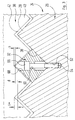
- Figures 2 and 3 show a first type of attachment the knife body 32 on the knife receptacles 30.
- the knife receptacles 30 are in the transverse direction milled centrally through a section of a peripheral rib and reach twice the normal height of the Circumferential rib.
- the peripheral ribs have a triangular cross section with an outside opening angle of 90 °.
- the knife receptacles 30 also have one Lateral boundary surfaces set at 90 °. In this way, the knife receptacles 30 at one Angular position a smooth continuation of the flanks of neighboring Circumferential ribs.
- the knife bodies 32 are square prisms. Your in Direction of rotation front or rear end faces in the present description and claims collectively referred to as main surfaces. The distance of the Main surfaces are also called the thickness or length of the knife body referred to, the edge length of the main faces also short as the edge length of the knife body.
- a mounting hole stepped from both sides 60 is provided.
- Threaded hole 62 is provided, and the knife body 32 each by a threaded bolt 64 on a threaded bore 62 screwed, the head 66 of the threaded bolt completely in the expanded designated 68 Bore section of mounting hole 60 receptacle finds. In this way, the knife bodies 32 are fixed, however releasably connected to the roller base body 26.
- the edge length is Knife body 32 larger than the length of the flanks of the Circumferential ribs 28.
- the tip of the Knife body 32 each by a corresponding distance d over the tip of the associated circumferential rib 28 over. This means that if you have a small Gap s between the counter knife 38 and the knife bodies 32 sets a correspondingly larger gap S * between the flanks of the circumferential ribs 28 and the Counter knife 38 has.
- the piercing point is the axis of the shredding roller 24 denoted by M in the drawing plane.
- M the axis of the threaded hole 62 so that it intersects the point M, so the outermost tip in working direction a knife body 32 at the same distance around the Roller axis revolve like the rear extreme tip.
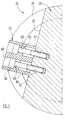
- the bottom of the knife holder is 30 compared to the case described above by an angle w tilted so that the axis of the threaded bore 62 and thus the center plane of the knife body 32 in the direction of rotation seen in front of the axis of the shredding roller marked with M. 24 lies.
- the knife body 32 twice the thickness as in the embodiment according to Figure 2, and in it are in the thickness direction spaced two mounting holes 60 and 60 'are provided.
- the bottom of the knife holder 30 also has two threaded bores 62, 62 ', the distance between which corresponds to the mounting holes 60, 60 '.
- the knife body 32 is now on by two threaded bolts 64, 64 ' braced the bottom of the knife holder 30 and thus particularly reliable against tilting moments and impact loads secured.
- the knife body according to FIG. 4 can do the same as the knife body are implemented four times according to FIG two new cutting edges in engagement with the teeth of the Bring counter knife 38.
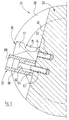
- Figure 5 is in the working direction seen back section of the thick Knife body of Figure 4 by a support body 70th replaced, an upper, designed as a square Support portion 72 and a lower threaded portion 74 having.
- the latter is in the rear threaded hole 62 ' turned in. So that the support section 72 when screwing in of the support body 70 on the adjacent circumferential ribs and can run past the side walls of the knife holder 30, is coaxial to the threaded bore 62 a cylindrical cut 76 of the adjacent circumferential ribs are provided.
- the knife attachment according to Figure 5 is with respect to Support and tilt protection of the knife body 32 essentially equivalent to the knife attachment Figure 4; but one can have smaller thickness knife bodies use.
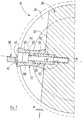
- the support body 78 is complementary in its underside to the shape of the knife holder 30 and puts in his upper section a smooth continuation of the peripheral rib 28 represents
- Figure 7 shows an integrated into the interior of the knife body Support device, which in particular also allows knife bodies with concave main surfaces with a simple Support the geometry of the support body well.
- the threaded bore 62 is provided with a counter bore 80, the same diameter and slightly smaller Like counterbore 68 of knife body 32, depth has In the aligned counter bores 68 and 80 is one Support sleeve 82 used without play, the length of which corresponds to twice the length of the counterbore 80. In order to the support sleeve 82 holds transverse impact loads and tilting moments reliably away from the threaded bolt 64, but does not hinder firm clamping of the knife body 32 with the bottom of the knife holder 30.
- knife attachment according to FIG. 7 can also be used in conjunction with knife bodies 32, which have major concave surfaces as shown at 84.
Landscapes
- Engineering & Computer Science (AREA)
- Food Science & Technology (AREA)
- Crushing And Pulverization Processes (AREA)
- Crushing And Grinding (AREA)
Claims (13)
- Cylindre de broyeur pour un broyeur, avec un corps de broyeur (26), avec un grand nombre de logements pour lames (30) prévus dans la surface circonférentielle du corps de broyeur et avec un grand nombre de corps de lames (32) fixés de façon amovible dans les logements pour lames (30), les surfaces principales des corps de lames (32) ayant la forme d'un losange et les logements pour lames (30) ayant une section en forme de V, l'angle d'ouverture des logements pour lames correspondant à l'angle d'ouverture du losange de la section des corps de lames, et les logements pour lames (30) présentant des trous filetés (62) et les corps de lames (32) présentant des trous de montage (60) parallèles à leurs surfaces principales avant et arrière, au travers desquels passe un boulon fileté (64) vissé dans un trou fileté (62) du logement pour lame (32) correspondant, caractérisé en ce que les trous de montage (60) s'étendent le long des diagonales de la surface centrale des corps de lame (32) et en ce qu'au moins un trou fileté part respectivement du fond des logements pour lames (30).
- Cylindre de broyeur selon la revendication 1, caractérisé en ce que les corps de lame (32) sont formés de façon symétrique au trou de montage (60).
- Cylindre de broyeur selon la revendication 1 ou 2, caractérisé en ce que les surfaces principales des corps de lame (32) ont la forme d'un carré.
- Cylindre de broyeur selon l'une des revendications 1 à 3, caractérisé en ce que les trous de montage (60) présentent des contre-trous (68), dans lesquels une tête (66) d'un boulon fileté (64) peut se loger entièrement.
- Cylindre de broyeur selon l'une des revendications 1 à 4, caractérisé en ce que les corps de lame (32) vus dans le sens longitudinal des logements pour lames (30) ont une section invariable et que la géométrie des logements pour lames (30) et le point de fixation des corps de lame (32) sont sélectionnés de telle sorte que les arêtes extérieures arrière des corps de lame (32), vues dans le sens de rotation de travail du cylindre broyeur (24), passent sur un cercle présentant un diamètre inférieur à celui des arêtes extérieures avant des corps de lames (32) vues dans le sens de rotation de travail.
- Cylindre de broyeur selon la revendication 5, caractérisé en ce que les corps de lames (32) sont placés de manière excentrique par rapport au point médian de l'arête du cylindre définie par le fond du logement pour lames (30)
- Corps de lames selon l'une des revendications 1 à 6, caractérisé en ce que deux trous filetés (62, 62') espacés l'un de l'autre dans le sens longitudinal des logements pour lames (30) sont prévus dans le fond des logements pour lames (30) et qu'ils forment des parties prismatiques de longueur correspondant aux corps de lames (32) et qu'ils présentent respectivement deux trous de montage (60, 60') en fonction de l'écart des trous filetés (62, 62') et qu'ils sont raccordés respectivement au corps de base du cylindre (26) par deux boulons filetés (64, 64').
- Cylindre de broyeur selon l'une des revendications 1 à 7, caractérisé en ce que deux trous filetés (62, 62') espacés l'un de l'autre sont prévus sur le fond des logements pour lames (30) et qu'un corps de soutien (70, 78) est, vu dans le sens de rotation de travail, fixé sur le trou fileté arrière des deux trous filetés, la face terminale avant duquel, vue dans le sens de rotation de travail, étant adjacente au dos d'un corps de lame (32), qui est fixé sur le trou fileté avant des trous filetés (62, 62') vu dans le sens de rotation de travail.
- Cylindre de broyeur selon la revendication 8, caractérisé en ce que le corps de soutien (70) est une barre ronde avec un aplatissement ou une barre carrée.
- Cylindre de broyeur selon la revendication 9, caractérisé en ce qu'une section filetée (74) est formée sur le corps de soutien (70), section qui est vissée dans le trou fileté (62') correspondant.
- Cylindre de broyeur selon la revendication 8, caractérisé en ce que le corps d'appui (78) présente une surface de limitation intérieure radiale, complémentaire à la surface de limitation des logements pour lames (30), et une surface de limitation extérieure radiale représentant un prolongement plan de la surface extérieure de la nervure de circonférence (28) du corps de broyeur (26).
- Corps de lame selon l'une des revendications 1 à 6, caractérisé en ce que le trou fileté (62) présente un contre-trou (80) et que le trou de montage (60) présente un contre-trou (68), ces deux contre-trous ayant le même diamètre, et en ce qu'une douille d'appui (82) s'étend sans jeu dans les deux contre-trous (68, 30), dans laquelle douille passe le boulon fileté (64).
- Broyeur avec un cylindre de broyeur selon l'une des revendications 6 à 12, caractérisé en ce qu'une contre-lame (38) munie d'un grand nombre de dents (40) qui ont prise entre les corps de lame (32) en rotation et portés par le cylindre broyeur (24), sont décalées de telle manière par rapport à l'axe du cylindre broyeur (24) ou sont orientées de telle manière par rapport à un niveau passant par l'axe du cylindre broyeur (24), que les surfaces principales des corps de lames (32) et des contre-lames (38) agissant ensemble sont essentiellement parallèles l'une par rapport à l'autre lors de l'approche des corps de lame (32) sur la contre-lame (38).
Applications Claiming Priority (3)
| Application Number | Priority Date | Filing Date | Title |
|---|---|---|---|
| DE19506848 | 1995-02-15 | ||
| DE19506848A DE19506848A1 (de) | 1995-02-15 | 1995-02-15 | Zerkleinerungswalze und Zerkleinerungsmaschine mit einer solchen |
| PCT/EP1996/000588 WO1996025231A1 (fr) | 1995-02-15 | 1996-02-12 | Cylindre de broyeur et broyeur equipe d'un tel cylindre__________ |
Publications (2)
| Publication Number | Publication Date |
|---|---|
| EP0809533A1 EP0809533A1 (fr) | 1997-12-03 |
| EP0809533B1 true EP0809533B1 (fr) | 2000-05-17 |
Family
ID=7755181
Family Applications (1)
| Application Number | Title | Priority Date | Filing Date |
|---|---|---|---|
| EP96904065A Revoked EP0809533B1 (fr) | 1995-02-15 | 1996-02-12 | Cylindre de broyeur et broyeur equipe d'un tel cylindre |
Country Status (4)
| Country | Link |
|---|---|
| EP (1) | EP0809533B1 (fr) |
| AT (1) | ATE192946T1 (fr) |
| DE (2) | DE19506848A1 (fr) |
| WO (1) | WO1996025231A1 (fr) |
Cited By (1)
| Publication number | Priority date | Publication date | Assignee | Title |
|---|---|---|---|---|
| US9144803B2 (en) | 2011-06-24 | 2015-09-29 | Vecoplan Llc | Shredder with multi-point cutters |
Families Citing this family (4)
| Publication number | Priority date | Publication date | Assignee | Title |
|---|---|---|---|---|
| NL1009850C2 (nl) * | 1998-08-12 | 2000-02-15 | Visno Maschf B V | Inrichting voor het verkleinen en vermalen van grof materiaal. |
| FR2785205B1 (fr) | 1998-10-30 | 2001-01-26 | Phenix Ind | Dispositif de broyage de dechets |
| FI20030159L (fi) * | 2003-02-03 | 2004-08-04 | Bmh Wood Technology Oy | Murskainroottorin ja sen vastaterärakenteen yhdistelmä |
| CN105435921B (zh) * | 2016-01-06 | 2018-08-31 | 河北华明木塑制品有限公司 | 一种单齿辊破碎机 |
Family Cites Families (3)
| Publication number | Priority date | Publication date | Assignee | Title |
|---|---|---|---|---|
| US4176800A (en) * | 1978-01-11 | 1979-12-04 | Garbalizer Corporation Of America | Materials reduction structure |
| DE8915534U1 (de) * | 1989-09-28 | 1990-09-06 | Vecoplan GmbH Maschinenfabrik, 5439 Bad Marienberg | Zerkleinerungsvorrichtung für Abfälle |
| DE4242740C2 (de) * | 1992-12-17 | 1998-09-10 | Holz Metall Abfall Recyclingte | Zerkleinerungsmaschine |
-
1995
- 1995-02-15 DE DE19506848A patent/DE19506848A1/de not_active Withdrawn
-
1996
- 1996-02-12 WO PCT/EP1996/000588 patent/WO1996025231A1/fr not_active Ceased
- 1996-02-12 DE DE59605250T patent/DE59605250D1/de not_active Expired - Fee Related
- 1996-02-12 EP EP96904065A patent/EP0809533B1/fr not_active Revoked
- 1996-02-12 AT AT96904065T patent/ATE192946T1/de not_active IP Right Cessation
Cited By (1)
| Publication number | Priority date | Publication date | Assignee | Title |
|---|---|---|---|---|
| US9144803B2 (en) | 2011-06-24 | 2015-09-29 | Vecoplan Llc | Shredder with multi-point cutters |
Also Published As
| Publication number | Publication date |
|---|---|
| WO1996025231A1 (fr) | 1996-08-22 |
| DE59605250D1 (de) | 2000-06-21 |
| DE19506848A1 (de) | 1996-08-22 |
| ATE192946T1 (de) | 2000-06-15 |
| EP0809533A1 (fr) | 1997-12-03 |
Similar Documents
| Publication | Publication Date | Title |
|---|---|---|
| DE10215833A1 (de) | Schneidkörper mit einem Schlegel | |
| DE19857451A1 (de) | Schneid- oder Brechwerkzeug sowie Schneideinsatz für dieses | |
| DE102005026816B4 (de) | Zerkleinerungsvorrichtung | |
| DE2615329A1 (de) | Fraeser | |
| DE8902716U1 (de) | Umlaufendes Schneidwerkzeug, insbesondere zum Stranggranulieren von Kunststoffen | |
| EP0809533B1 (fr) | Cylindre de broyeur et broyeur equipe d'un tel cylindre | |
| EP0401620B1 (fr) | Rotor avec calottes de protection | |
| EP2374544B1 (fr) | Dispositif de broyage de matériaux compostables | |
| DE102009033584A1 (de) | Messer für eine Zerkleinerungsmaschine und Verwendung eines solchen in einer Zerkleinerungsmaschine | |
| DE102007043687A1 (de) | Werkzeug für eine Zerkleinerungsvorrichtung für kompostierbares Abfallmaterial | |
| DE2943567A1 (de) | Reisszahnwalze und damit bestueckte reisswalenzerkleinerungsmaschinen | |
| DE19515867A1 (de) | Zerkleinerungsmaschine | |
| DE20309648U1 (de) | Zerkleinerungsanlage | |
| AT408968B (de) | Vorrichtung zur verkleinerung der überdimensionierten fraktion von spänen | |
| DE20309650U1 (de) | Zerkleinerungsmaschine | |
| AT398711B (de) | Zylindrischer rotor | |
| CH426697A (de) | Maschine zum Abbauen von Feststoffen | |
| DE3808059C2 (de) | Vorrichtung zum Zerkleinern von Müll od. dgl. Haufwerk | |
| DE2341408C2 (de) | Vorrichtung zum Zerkleinern von Büromaterial | |
| EP0956901A1 (fr) | Arbre coupant muni d'éléments coupants pour appareil désintégrateur | |
| DE20309649U1 (de) | Zerkleinerungsmaschine | |
| DE8214553U1 (de) | Rotor für Hammermühlen | |
| DE9204176U1 (de) | Vorrichtung zum Zerkleinern von Holzstücken, insbesondere von Restholz | |
| DE19634465A1 (de) | Zerkleinerungswerkzeug für Shredder | |
| DE8460076U1 (de) | Schrotmühle |
Legal Events
| Date | Code | Title | Description |
|---|---|---|---|
| PUAI | Public reference made under article 153(3) epc to a published international application that has entered the european phase |
Free format text: ORIGINAL CODE: 0009012 |
|
| 17P | Request for examination filed |
Effective date: 19970801 |
|
| AK | Designated contracting states |
Kind code of ref document: A1 Designated state(s): AT DE GB NL SE |
|
| GRAG | Despatch of communication of intention to grant |
Free format text: ORIGINAL CODE: EPIDOS AGRA |
|
| 17Q | First examination report despatched |
Effective date: 19990122 |
|
| GRAG | Despatch of communication of intention to grant |
Free format text: ORIGINAL CODE: EPIDOS AGRA |
|
| GRAH | Despatch of communication of intention to grant a patent |
Free format text: ORIGINAL CODE: EPIDOS IGRA |
|
| GRAH | Despatch of communication of intention to grant a patent |
Free format text: ORIGINAL CODE: EPIDOS IGRA |
|
| GRAA | (expected) grant |
Free format text: ORIGINAL CODE: 0009210 |
|
| AK | Designated contracting states |
Kind code of ref document: B1 Designated state(s): AT DE GB NL SE |
|
| PG25 | Lapsed in a contracting state [announced via postgrant information from national office to epo] |
Ref country code: NL Free format text: LAPSE BECAUSE OF FAILURE TO SUBMIT A TRANSLATION OF THE DESCRIPTION OR TO PAY THE FEE WITHIN THE PRESCRIBED TIME-LIMIT Effective date: 20000517 |
|
| REF | Corresponds to: |
Ref document number: 192946 Country of ref document: AT Date of ref document: 20000615 Kind code of ref document: T |
|
| GBT | Gb: translation of ep patent filed (gb section 77(6)(a)/1977) |
Effective date: 20000517 |
|
| REF | Corresponds to: |
Ref document number: 59605250 Country of ref document: DE Date of ref document: 20000621 |
|
| PG25 | Lapsed in a contracting state [announced via postgrant information from national office to epo] |
Ref country code: SE Free format text: LAPSE BECAUSE OF FAILURE TO SUBMIT A TRANSLATION OF THE DESCRIPTION OR TO PAY THE FEE WITHIN THE PRESCRIBED TIME-LIMIT Effective date: 20000817 |
|
| EN | Fr: translation not filed | ||
| NLV1 | Nl: lapsed or annulled due to failure to fulfill the requirements of art. 29p and 29m of the patents act | ||
| PG25 | Lapsed in a contracting state [announced via postgrant information from national office to epo] |
Ref country code: AT Free format text: LAPSE BECAUSE OF NON-PAYMENT OF DUE FEES Effective date: 20010212 |
|
| PLBQ | Unpublished change to opponent data |
Free format text: ORIGINAL CODE: EPIDOS OPPO |
|
| PLBI | Opposition filed |
Free format text: ORIGINAL CODE: 0009260 |
|
| PLBF | Reply of patent proprietor to notice(s) of opposition |
Free format text: ORIGINAL CODE: EPIDOS OBSO |
|
| 26 | Opposition filed |
Opponent name: HOLZMAG AG RECYCLING TECHNOLOGY Effective date: 20010216 |
|
| PLBF | Reply of patent proprietor to notice(s) of opposition |
Free format text: ORIGINAL CODE: EPIDOS OBSO |
|
| PLBF | Reply of patent proprietor to notice(s) of opposition |
Free format text: ORIGINAL CODE: EPIDOS OBSO |
|
| PG25 | Lapsed in a contracting state [announced via postgrant information from national office to epo] |
Ref country code: DE Free format text: LAPSE BECAUSE OF NON-PAYMENT OF DUE FEES Effective date: 20011201 |
|
| REG | Reference to a national code |
Ref country code: GB Ref legal event code: IF02 |
|
| PGFP | Annual fee paid to national office [announced via postgrant information from national office to epo] |
Ref country code: GB Payment date: 20020214 Year of fee payment: 7 |
|
| RDAH | Patent revoked |
Free format text: ORIGINAL CODE: EPIDOS REVO |
|
| RDAG | Patent revoked |
Free format text: ORIGINAL CODE: 0009271 |
|
| STAA | Information on the status of an ep patent application or granted ep patent |
Free format text: STATUS: PATENT REVOKED |
|
| 27W | Patent revoked |
Effective date: 20030202 |
|
| GBPR | Gb: patent revoked under art. 102 of the ep convention designating the uk as contracting state |
Free format text: 20030202 |