EP0808732B1 - Verfahren und Gerät für das Fahrwerk-Regelungssystem eines Kraftfahrzeuges - Google Patents
Verfahren und Gerät für das Fahrwerk-Regelungssystem eines Kraftfahrzeuges Download PDFInfo
- Publication number
- EP0808732B1 EP0808732B1 EP97201167A EP97201167A EP0808732B1 EP 0808732 B1 EP0808732 B1 EP 0808732B1 EP 97201167 A EP97201167 A EP 97201167A EP 97201167 A EP97201167 A EP 97201167A EP 0808732 B1 EP0808732 B1 EP 0808732B1
- Authority
- EP
- European Patent Office
- Prior art keywords
- vehicle
- index
- yaw rate
- chassis
- control
- Prior art date
- Legal status (The legal status is an assumption and is not a legal conclusion. Google has not performed a legal analysis and makes no representation as to the accuracy of the status listed.)
- Expired - Lifetime
Links
- 238000000034 method Methods 0.000 title claims description 21
- 230000001133 acceleration Effects 0.000 claims description 33
- 230000006870 function Effects 0.000 claims description 3
- 230000010354 integration Effects 0.000 claims 2
- 230000000977 initiatory effect Effects 0.000 claims 1
- 238000001514 detection method Methods 0.000 description 4
- 238000010586 diagram Methods 0.000 description 3
- 230000003068 static effect Effects 0.000 description 3
- 230000036461 convulsion Effects 0.000 description 2
- 230000000694 effects Effects 0.000 description 2
- 229910000078 germane Inorganic materials 0.000 description 2
- 238000005259 measurement Methods 0.000 description 2
- 230000005540 biological transmission Effects 0.000 description 1
- 230000004044 response Effects 0.000 description 1
- 230000011664 signaling Effects 0.000 description 1
Images


Classifications
-
- B—PERFORMING OPERATIONS; TRANSPORTING
- B60—VEHICLES IN GENERAL
- B60T—VEHICLE BRAKE CONTROL SYSTEMS OR PARTS THEREOF; BRAKE CONTROL SYSTEMS OR PARTS THEREOF, IN GENERAL; ARRANGEMENT OF BRAKING ELEMENTS ON VEHICLES IN GENERAL; PORTABLE DEVICES FOR PREVENTING UNWANTED MOVEMENT OF VEHICLES; VEHICLE MODIFICATIONS TO FACILITATE COOLING OF BRAKES
- B60T8/00—Arrangements for adjusting wheel-braking force to meet varying vehicular or ground-surface conditions, e.g. limiting or varying distribution of braking force
- B60T8/17—Using electrical or electronic regulation means to control braking
- B60T8/1755—Brake regulation specially adapted to control the stability of the vehicle, e.g. taking into account yaw rate or transverse acceleration in a curve
-
- B—PERFORMING OPERATIONS; TRANSPORTING
- B60—VEHICLES IN GENERAL
- B60G—VEHICLE SUSPENSION ARRANGEMENTS
- B60G17/00—Resilient suspensions having means for adjusting the spring or vibration-damper characteristics, for regulating the distance between a supporting surface and a sprung part of vehicle or for locking suspension during use to meet varying vehicular or surface conditions, e.g. due to speed or load
- B60G17/015—Resilient suspensions having means for adjusting the spring or vibration-damper characteristics, for regulating the distance between a supporting surface and a sprung part of vehicle or for locking suspension during use to meet varying vehicular or surface conditions, e.g. due to speed or load the regulating means comprising electric or electronic elements
- B60G17/018—Resilient suspensions having means for adjusting the spring or vibration-damper characteristics, for regulating the distance between a supporting surface and a sprung part of vehicle or for locking suspension during use to meet varying vehicular or surface conditions, e.g. due to speed or load the regulating means comprising electric or electronic elements characterised by the use of a specific signal treatment or control method
- B60G17/0185—Resilient suspensions having means for adjusting the spring or vibration-damper characteristics, for regulating the distance between a supporting surface and a sprung part of vehicle or for locking suspension during use to meet varying vehicular or surface conditions, e.g. due to speed or load the regulating means comprising electric or electronic elements characterised by the use of a specific signal treatment or control method for failure detection
-
- B—PERFORMING OPERATIONS; TRANSPORTING
- B60—VEHICLES IN GENERAL
- B60G—VEHICLE SUSPENSION ARRANGEMENTS
- B60G17/00—Resilient suspensions having means for adjusting the spring or vibration-damper characteristics, for regulating the distance between a supporting surface and a sprung part of vehicle or for locking suspension during use to meet varying vehicular or surface conditions, e.g. due to speed or load
- B60G17/015—Resilient suspensions having means for adjusting the spring or vibration-damper characteristics, for regulating the distance between a supporting surface and a sprung part of vehicle or for locking suspension during use to meet varying vehicular or surface conditions, e.g. due to speed or load the regulating means comprising electric or electronic elements
- B60G17/0195—Resilient suspensions having means for adjusting the spring or vibration-damper characteristics, for regulating the distance between a supporting surface and a sprung part of vehicle or for locking suspension during use to meet varying vehicular or surface conditions, e.g. due to speed or load the regulating means comprising electric or electronic elements characterised by the regulation being combined with other vehicle control systems
-
- B—PERFORMING OPERATIONS; TRANSPORTING
- B60—VEHICLES IN GENERAL
- B60G—VEHICLE SUSPENSION ARRANGEMENTS
- B60G2400/00—Indexing codes relating to detected, measured or calculated conditions or factors
- B60G2400/10—Acceleration; Deceleration
- B60G2400/104—Acceleration; Deceleration lateral or transversal with regard to vehicle
-
- B—PERFORMING OPERATIONS; TRANSPORTING
- B60—VEHICLES IN GENERAL
- B60G—VEHICLE SUSPENSION ARRANGEMENTS
- B60G2400/00—Indexing codes relating to detected, measured or calculated conditions or factors
- B60G2400/20—Speed
- B60G2400/208—Speed of wheel rotation
-
- B—PERFORMING OPERATIONS; TRANSPORTING
- B60—VEHICLES IN GENERAL
- B60G—VEHICLE SUSPENSION ARRANGEMENTS
- B60G2400/00—Indexing codes relating to detected, measured or calculated conditions or factors
- B60G2400/40—Steering conditions
- B60G2400/41—Steering angle
- B60G2400/412—Steering angle of steering wheel or column
-
- B—PERFORMING OPERATIONS; TRANSPORTING
- B60—VEHICLES IN GENERAL
- B60G—VEHICLE SUSPENSION ARRANGEMENTS
- B60G2600/00—Indexing codes relating to particular elements, systems or processes used on suspension systems or suspension control systems
- B60G2600/02—Retarders, delaying means, dead zones, threshold values, cut-off frequency, timer interruption
-
- B—PERFORMING OPERATIONS; TRANSPORTING
- B60—VEHICLES IN GENERAL
- B60G—VEHICLE SUSPENSION ARRANGEMENTS
- B60G2600/00—Indexing codes relating to particular elements, systems or processes used on suspension systems or suspension control systems
- B60G2600/04—Means for informing, instructing or displaying
-
- B—PERFORMING OPERATIONS; TRANSPORTING
- B60—VEHICLES IN GENERAL
- B60G—VEHICLE SUSPENSION ARRANGEMENTS
- B60G2600/00—Indexing codes relating to particular elements, systems or processes used on suspension systems or suspension control systems
- B60G2600/08—Failure or malfunction detecting means
-
- B—PERFORMING OPERATIONS; TRANSPORTING
- B60—VEHICLES IN GENERAL
- B60G—VEHICLE SUSPENSION ARRANGEMENTS
- B60G2600/00—Indexing codes relating to particular elements, systems or processes used on suspension systems or suspension control systems
- B60G2600/16—Integrating means, i.e. integral control
-
- B—PERFORMING OPERATIONS; TRANSPORTING
- B60—VEHICLES IN GENERAL
- B60G—VEHICLE SUSPENSION ARRANGEMENTS
- B60G2600/00—Indexing codes relating to particular elements, systems or processes used on suspension systems or suspension control systems
- B60G2600/70—Computer memory; Data storage, e.g. maps for adaptive control
-
- B—PERFORMING OPERATIONS; TRANSPORTING
- B60—VEHICLES IN GENERAL
- B60G—VEHICLE SUSPENSION ARRANGEMENTS
- B60G2800/00—Indexing codes relating to the type of movement or to the condition of the vehicle and to the end result to be achieved by the control action
- B60G2800/01—Attitude or posture control
- B60G2800/012—Rolling condition
-
- B—PERFORMING OPERATIONS; TRANSPORTING
- B60—VEHICLES IN GENERAL
- B60G—VEHICLE SUSPENSION ARRANGEMENTS
- B60G2800/00—Indexing codes relating to the type of movement or to the condition of the vehicle and to the end result to be achieved by the control action
- B60G2800/21—Traction, slip, skid or slide control
-
- B—PERFORMING OPERATIONS; TRANSPORTING
- B60—VEHICLES IN GENERAL
- B60G—VEHICLE SUSPENSION ARRANGEMENTS
- B60G2800/00—Indexing codes relating to the type of movement or to the condition of the vehicle and to the end result to be achieved by the control action
- B60G2800/22—Braking, stopping
-
- B—PERFORMING OPERATIONS; TRANSPORTING
- B60—VEHICLES IN GENERAL
- B60G—VEHICLE SUSPENSION ARRANGEMENTS
- B60G2800/00—Indexing codes relating to the type of movement or to the condition of the vehicle and to the end result to be achieved by the control action
- B60G2800/24—Steering, cornering
-
- B—PERFORMING OPERATIONS; TRANSPORTING
- B60—VEHICLES IN GENERAL
- B60G—VEHICLE SUSPENSION ARRANGEMENTS
- B60G2800/00—Indexing codes relating to the type of movement or to the condition of the vehicle and to the end result to be achieved by the control action
- B60G2800/24—Steering, cornering
- B60G2800/244—Oversteer
-
- B—PERFORMING OPERATIONS; TRANSPORTING
- B60—VEHICLES IN GENERAL
- B60G—VEHICLE SUSPENSION ARRANGEMENTS
- B60G2800/00—Indexing codes relating to the type of movement or to the condition of the vehicle and to the end result to be achieved by the control action
- B60G2800/24—Steering, cornering
- B60G2800/246—Understeer
-
- B—PERFORMING OPERATIONS; TRANSPORTING
- B60—VEHICLES IN GENERAL
- B60G—VEHICLE SUSPENSION ARRANGEMENTS
- B60G2800/00—Indexing codes relating to the type of movement or to the condition of the vehicle and to the end result to be achieved by the control action
- B60G2800/90—System Controller type
- B60G2800/92—ABS - Brake Control
-
- B—PERFORMING OPERATIONS; TRANSPORTING
- B60—VEHICLES IN GENERAL
- B60T—VEHICLE BRAKE CONTROL SYSTEMS OR PARTS THEREOF; BRAKE CONTROL SYSTEMS OR PARTS THEREOF, IN GENERAL; ARRANGEMENT OF BRAKING ELEMENTS ON VEHICLES IN GENERAL; PORTABLE DEVICES FOR PREVENTING UNWANTED MOVEMENT OF VEHICLES; VEHICLE MODIFICATIONS TO FACILITATE COOLING OF BRAKES
- B60T2260/00—Interaction of vehicle brake system with other systems
- B60T2260/06—Active Suspension System
-
- B—PERFORMING OPERATIONS; TRANSPORTING
- B60—VEHICLES IN GENERAL
- B60T—VEHICLE BRAKE CONTROL SYSTEMS OR PARTS THEREOF; BRAKE CONTROL SYSTEMS OR PARTS THEREOF, IN GENERAL; ARRANGEMENT OF BRAKING ELEMENTS ON VEHICLES IN GENERAL; PORTABLE DEVICES FOR PREVENTING UNWANTED MOVEMENT OF VEHICLES; VEHICLE MODIFICATIONS TO FACILITATE COOLING OF BRAKES
- B60T2260/00—Interaction of vehicle brake system with other systems
- B60T2260/09—Complex systems; Conjoint control of two or more vehicle active control systems
Definitions
- This invention relates to a vehicle chassis system control method and apparatus.
- chassis system controls such as those referred to as active brake controls, are designed to help a vehicle stay on its intended path, that is, to avoid deviation between the direction of vehicle travel and an intended direction defined by a line between either the left front and left rear vehicle wheels or the right front and right rear vehicle wheels.
- EP-A-0 557 692 discloses a vehicle chassis system control method and apparatus in accordance with the preamble of claims 1 and 9 respectively.
- the yaw rate, the vehicle speed and the lateral acceleration of the vehicle is determined.
- the steering angle of at least one of the vehicle axes is corrected.
- this invention provides a vehicle chassis system control method and apparatus for use with control systems such as active brake controls.
- this invention determines when a vehicle has deviated too far from its intended course and direction, that is when an angle between the vehicle's actual direction of travel and a direction defined by a line between the front and rear left or right tires, is so large, that the active brake control is ineffective and is preferably switched off.
- this invention provides a means for signaling an active brake control mode or other chassis control mode to turn off when deviation from the vehicle intended course and direction is experienced to a sufficient degree to render such control mode ineffective.
- a yaw rate sensor providing a signal indicative of a yaw rate of the vehicle body
- a vehicle speed sensor
- the vehicle 10 includes four wheels 20, 22, 24 and 26, each with associated wheel brakes 12, 14, 16 and 18.
- Each wheel 20-26 has a wheel speed sensor 28, 30, 32 and 34 of a known type providing wheel speed information to the microprocessor-based controller 46.
- the controller 46 also receives steering wheel position information for steering wheel 42 from position sensor 40.
- Position sensor 40 may be a digital sensor that increments a digital output signal with each degree or partial degree of movement of the steering wheel 42 in one direction and decrements the digital output signal with each degree or partial degree of movement in the opposite direction.
- the steering wheel sensor 40 need not have an inherent center position signal capability, but such capability may be included to serve as a guide indicating that the steering wheel is approximately on center.
- Such steering wheel sensors 40 are well known to those skilled in the art.
- EP-A-0 809 167 entitled, "Sensor-Responsive Control Method and Apparatus," assigned to the assignee of this invention, is used by the controller 46 to accurately calibrate the sensor 40 and provide accurate steering wheel sensor information therefrom.
- the disclosure of the above-mentioned EP-A-0 809 167 is incorporated herein by reference.
- Controller 46 also receives signals from yaw rate sensor 36 and lateral accelerometer 38 to effect the controls described herein.
- the controller 46 in general, controls a brake actuator or actuators 44 for controlling the wheel brakes 12, 14, 16 and 18 to provide any suitable type of chassis control for the vehicle.
- Various example brake actuators 44 are well known to those skilled in the art and need not be set forth herein in detail.
- the active brake controls are not germane to this invention and may be any type of control presently known or in the future known to those skilled in the art, further detail of such controls are not set forth herein. Those skilled in the art will recognize that the brake control is considered generic for purposes of this description and the brake control referred to herein may encompass any known brake control.
- off course and intended direction means the vehicle is not traveling in a direction and course as normally would be directed by the vehicle tires. That is, there is an angle, referred to as the slip angle, between a line indicating the direction of actual vehicle travel and a line between the front and rear vehicle tires (either left or right). For example, if the vehicle is experiencing rotational moment involving lateral sliding engagement between the vehicle tires and the road surface, then the slip angle is greater than zero. If the slip angle achieves a predetermined level, as further defined below, the condition is detected and the off course flag is set.
- the vehicle static test subroutine starts and moves to block 210 where it checks to determine if all of the following conditions are met: (a) the vehicle speed is below a vehicle speed threshold, for example 8 kph.; (b) the absolute value of the forward acceleration of the vehicle is below an acceleration threshold, for example, 3 m/s 2 ; (c) the yaw rate is below a yaw rate threshold, for example, 1.5 deg./s; (d) the yaw acceleration is below a yaw acceleration threshold, for example 8 deg./s 2 ; (e) the lateral acceleration is below a lateral acceleration threshold, for example 5 m/s 2 ; and (f) the lateral jerk, determined as the integral of lateral acceleration, is below a lateral jerk threshold, for example 0.5 g/s.
- Vehicle speed is determined either from the vehicle speed signal from the vehicle transmission or as the average of the wheel speeds of the undriven vehicle wheels, i.e., wheels 24 and 26 (figure 1) for a front wheel drive vehicle.
- Forward acceleration is determined either from a forward acceleration sensor or through differentiating the vehicle speed signal.
- Yaw rate is determined, for example, from the yaw rate sensor, calibration of which may be done in the manner described in the above-mentioned EP-A-0 809 167.
- Yaw acceleration is determined by differentiating the yaw rate and lateral acceleration is as measured by the lateral accelerometer.
- the subroutine in block 102 via blocks 122, 124 and 126, resets the off course flag if the vehicle static test is passed at block 124 or if the off course flag has been set for a predetermined time period, after which the control method shown resets the off course flag (block 106) until another off course detection (block 108, Figure 2) is made.
- a subroutine 144 for calculating the index ratio is shown.
- the subroutine 144 starts and moves to block 170 where the absolute value of the lateral acceleration is compared to the lateral acceleration threshold, Ay1. If is greater than the lateral acceleration threshold, then the absolute value of the lateral acceleration is used in determining the index ratio at block 172. If the absolute value of the lateral acceleration is not greater than the lateral acceleration threshold, then the value Ay used for determining the index ratio is set to a predetermined minimum, for example 0.1 g.
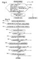
- the subroutine performed at block 152 is shown in Figure 8, which starts and moves to block 194 where it updates LMT2 from a look-up table based on vehicle speed.
- the function of the look-up table is shown in block 194.
- LMT2 is set at a fixed value, i.e., -50 but for higher vehicle speeds, LMT2 gradually reduces.
- the integral of the filtered under steer index is determined using an integrating filter.
- the routine continues to block 154 where it compares the integral of the filtered under steer index to a third threshold, LMT3.
- LMT3 is -150. If the integral of the filtered under steer index is not less than LMT3, the routine is exited. If the integral of the understeer index is less than LMT3, then the third criteria for determining an off course condition of the vehicle is met and the routine continues to block 156 where the last criteria for determining an off course condition of the vehicle is tested.
- the controller 46 implements a test for determining the condition of a vehicle, whether or not the vehicle is on or off its intended course and direction.
- the controller sets a control flag for a chassis control system such as an active brake control or a four wheel steer using brake control when an off course state is determined because it is recognized that once a vehicle is off course a predetermined amount, active brake control or other advanced chassis control systems are not implemented in returning the vehicle to course.
- the example apparatus schematic shown includes, within controller 46, internal processor 350, i.e., a microprocessor, and RAM 352.
- the processor 350 receives the sensor information including the vehicle speed, yaw rate and lateral acceleration as provided by the sensors 32, 34, 36 and 38.
- sequential operations are performed according to a software control program stored in ROM (not shown) or other non-volatile memory device to effect the steps described above.
- the controller 352 computes the indexes, INDEX1 and INDEX2, that are stored in memory locations 354 and 356.
- the indexes are controls for the active brake control on/off indicator, which, in the example above, is implemented as a flag stored in processor memory or RAM.
Landscapes
- Engineering & Computer Science (AREA)
- Mechanical Engineering (AREA)
- Transportation (AREA)
- Automation & Control Theory (AREA)
- Regulating Braking Force (AREA)
- Steering Control In Accordance With Driving Conditions (AREA)
Claims (11)
- Steuerverfahren für ein Fahrzeugchassissystem zum Gebrauch in einem Fahrzeug mit einem Gierratensensor (36), der ein Signal vorsieht, das eine Gierrate der Fahrzeugkarosserie angibt, einem Fahrzeuggeschwindigkeitssensor (28, 30, 32, 34), der ein Signal vorsieht, das eine Fahrzeuggeschwindigkeit angibt, einem Seitenbeschleunigungssensor (38), der ein Signal vorsieht, das eine Fahrzeugseitenbeschleunigung angibt, und einem Chassissteuersystem (46, 44, 12, 14, 16, 18) zur Steuerung einer Fahrzeuggierrate,
gekennzeichnet durch die Schritte, daß:in Ansprechen auf die Signale, die die Gierrate der Fahrzeugkarosserie, die Fahrzeuggeschwindigkeit (v) und die Fahrzeugseitenbeschleunigung (Ay) angeben, ein Indexverhältnis (INDEX 1) bestimmt wird;zunächst das Indexverhältnis (INDEX 1) mit einer ersten vorbestimmten Schwelle (LMT1) verglichen wird, die eine Grenze angibt, über der eine aktive Chassissteuerung nicht erwünscht ist (Schritt 146); undin Ansprechen auf den ersten Vergleich ein Signal (Schritt 158) gesetzt wird, das eine Beendigung der aktiven Chassissteuerung angibt, wenn das Indexverhältnis (INDEX 1) über der ersten vorbestimmten Schwelle (LMT1) liegt, wobei das Chassissteuersystem zeitweilig deaktiviert ist. - Steuerverfahren für ein Fahrzeugchassissystem nach Anspruch 1,
wobei das Indexverhältnis ein Verhältnis eines Produktes von Gierrate und Fahrzeuggeschwindigkeit zu Fahrzeugseitenbeschleunigung darstellt. - Steuerverfahren für ein Fahrzeugchassissystem nach Anspruch 1,
wobei das Fahrzeug auch einen Lenkradwinkelsensor (40) umfaßt, der ein Signal vorsieht, das einen Winkel eines Lenkrades des Fahrzeugs angibt, ferner gekennzeichnet durch die Schritte, daß:wobei der Schritt zum Setzen des Signales, das eine Beendigung der aktiven Chassissteuerung angibt, auch auf den zweiten Vergleichsschritt anspricht.ein zweites Indexverhältnis in Ansprechen auf die Signale bestimmt wird, die den Lenkradwinkel, die Fahrzeuggeschwindigkeit und die Gierrate (148) angeben; undzweitens der zweite Index mit einer zweiten vorbestimmten Schwelle (150) verglichen wird, - Steuerverfahren für ein Fahrzeugchassissystem nach Anspruch 3, mit dem Schritt, daß:die zweite vorbestimmte Schwelle als eine Funktion der Geschwindigkeit (194) bestimmt wird.
- Steuerverfahren für ein Fahrzeugchassissystem nach Anspruch 4,
wobei die zweite vorbestimmte Schwelle aus einer Nachschlagetabelle bestimmt wird, die in einem Computerspeicher (310, 312, 314) gespeichert ist. - Steuerverfahren für ein Fahrzeugchassissystem nach Anspruch 3, ferner mit den Schritten, daß:das zweite Indexverhältnis integriert wird, um ein Integrationsergebnis (152) zu bestimmen; unddrittens das Integrationsergebnis mit einer dritten vorbestimmten Schwelle verglichen wird, wobei der Schritt zum Setzen des Steuersignals auch auf den dritten Vergleich (156) anspricht.
- Steuerverfahren für ein Fahrzeugchassissystem nach Anspruch 6, ferner auch mit dem Schritt, daß viertens ein absoluter Wert der Gierrate mit einer vierten vorbestimmten Schwelle (156) verglichen wird, wobei der Schritt zum Setzen des Steuersignals auch auf den vierten Vergleich anspricht.
- Steuerverfahren für ein Fahrzeugchassissystem nach Anspruch 1, ferner mit den Schritten, daß:ein Zeitgeber angesteuert wird, wenn das Signal, das eine Beendigung der aktiven Chassissteuerung angibt, gesetzt ist (128); unddas Signal, das eine Beendigung der aktiven Chassissteuerung angibt, rückgesetzt wird, wenn der Zeitgeber einen Zeitüberschreitungswert (122, 126) erreicht.
- Steuervorrichtung für ein Fahrzeugchassissystem zum Gebrauch in einem Fahrzeug mit einem Gierratensensor (36), der ein Signal vorsieht, das eine Gierrate der Fahrzeugkarosserie angibt, einem Fahrzeuggeschwindigkeitssensor (28, 30, 32, 34), der ein Signal vorsieht, das eine Fahrzeuggeschwindigkeit angibt, einem Seitenbeschleunigungssensor (38), der ein Signal vorsieht, das eine Fahrzeugseitenbeschleunigung angibt, und einem Chassissteuersystem (46, 44, 12, 14, 16, 18) zur Steuerung einer Fahrzeuggierrate einschließlich einer Steuerung (46),
dadurch gekennzeichnet, daß die Vorrichtung ferner umfaßt:wobei die Anzeigeeinrichtung zur Anzeige eines An-/Aus-Zustandes der Bremsensteuerung zeitweilig in einen ausgeschalteten Zustand geschaltet wird, wenn das erste Indexverhältnis (INDEX 1) über einer vorbestimmten Schwelle liegt, was eine Grenze angibt, über welcher eine aktive Bremsensteuerung nicht erwünscht ist.eine Dividiereinrichtung (172) innerhalb der Steuerung zur Bestimmung eines ersten Indexverhältnisses (INDEX 1), das auf die Signale anspricht, die die Gierrate, Fahrzeuggeschwindigkeit und Fahrzeugseitenbeschleunigung angeben;einen Speicher (352) zur Speicherung des ersten Indexverhältnisses (INDEX 1); und daß das Chassissteuersystem ein aktives Bremsensteuersystem ist, das umfaßt:
eine Anzeigeeinrichtung (358) zur Anzeige eines An-/Aus-Zustandes einer Bremsensteuerung, die durch die Steuerung gehalten wird, - Steuervorrichtung für ein Fahrzeugchassissystem nach Anspruch 9, auch gekennzeichnet durch einen Zeitgeber (360), der auf die Anzeigeeinrichtung zur Anzeige eines An-/Aus-Zustandes der Bremsensteuerung anspricht, wobei der Zeitgeber angesteuert wird, wenn die An-/Aus-Anzeigeeinrichtung in einen ausgeschalteten Zustand geschaltet ist, und wobei die Anzeigeeinrichtung zur Anzeige eines An-/Aus-Zustands der Bremsensteuerung in einen eingeschalteten Zustand geschaltet ist, nachdem der Zeitgeber einen Zeitüberschreitungswert erreicht hat.
- Steuervorrichtung für ein Fahrzeugchassissystem nach Anspruch 9,
wobei der erste Index ein Verhältnis eines Produktes von Gierrate und Fahrzeuggeschwindigkeit zu Fahrzeugseitenbeschleunigung darstellt.
Applications Claiming Priority (2)
| Application Number | Priority Date | Filing Date | Title |
|---|---|---|---|
| US660150 | 1996-05-23 | ||
| US08/660,150 US5895433A (en) | 1996-05-23 | 1996-05-23 | Vehicle chassis system control method and apparatus |
Publications (2)
| Publication Number | Publication Date |
|---|---|
| EP0808732A1 EP0808732A1 (de) | 1997-11-26 |
| EP0808732B1 true EP0808732B1 (de) | 2001-12-19 |
Family
ID=24648370
Family Applications (1)
| Application Number | Title | Priority Date | Filing Date |
|---|---|---|---|
| EP97201167A Expired - Lifetime EP0808732B1 (de) | 1996-05-23 | 1997-04-21 | Verfahren und Gerät für das Fahrwerk-Regelungssystem eines Kraftfahrzeuges |
Country Status (3)
| Country | Link |
|---|---|
| US (1) | US5895433A (de) |
| EP (1) | EP0808732B1 (de) |
| DE (1) | DE69709235T2 (de) |
Cited By (1)
| Publication number | Priority date | Publication date | Assignee | Title |
|---|---|---|---|---|
| DE10330895A1 (de) * | 2003-07-09 | 2005-02-17 | Daimlerchrysler Ag | Ausregelung von Geradeauslaufstörungen eines Kraftfahrzeugs |
Families Citing this family (14)
| Publication number | Priority date | Publication date | Assignee | Title |
|---|---|---|---|---|
| DE19749058A1 (de) * | 1997-07-02 | 1999-01-07 | Bosch Gmbh Robert | Verfahren und Vorrichtung zur Regelung einer die Fahrzeugbewegung repräsentierenden Bewegungsgröße |
| KR19990062746A (ko) * | 1997-12-24 | 1999-07-26 | 모찌즈키 아키히로 | 쥐센서의 출력치 보정 및 이상 검출 |
| DE19859966A1 (de) * | 1998-12-29 | 2000-07-13 | Bosch Gmbh Robert | Vorrichtung und Verfahren zur Stabilisierung eines Fahrzeuges |
| DE19964048A1 (de) * | 1999-06-30 | 2001-01-04 | Bosch Gmbh Robert | Verfahren und Einrichtung zum Stabilisieren eines Straßenfahrzeugs |
| US6204758B1 (en) * | 1999-07-23 | 2001-03-20 | Schrader-Bridgeport International, Inc. | System to automatically determine wheel position for automotive remote tire monitoring system |
| DE10027006B4 (de) * | 2000-05-31 | 2014-09-04 | Robert Bosch Gmbh | System zur Steuerung / Regelung der Betriebsabläufe bei einem Kraftfahrzeug und ein Verfahren zum Starten eines solchen Systems |
| DE10316760A1 (de) | 2003-04-10 | 2004-10-28 | Continental Aktiengesellschaft | Verfahren zum Betreiben einer Niveauregelanlage eines Kraftfahrzeuges |
| US7698034B2 (en) * | 2004-01-06 | 2010-04-13 | Gm Global Technology Operations, Inc. | Integrating active front steering and vehicle stability brake control |
| US7349778B2 (en) * | 2004-06-09 | 2008-03-25 | General Motors Corporation | Real-time vehicle dynamics estimation system |
| DE102006030593B4 (de) * | 2006-07-03 | 2013-06-13 | Continental Automotive Gmbh | Verfahren zur Ruhelagenbestimmung eines Fahrzeugs |
| US8744689B2 (en) * | 2007-07-26 | 2014-06-03 | Hitachi, Ltd. | Drive controlling apparatus for a vehicle |
| JP4997065B2 (ja) * | 2007-10-29 | 2012-08-08 | 日立オートモティブシステムズ株式会社 | 車両制御装置 |
| EP2135782B1 (de) | 2008-06-18 | 2011-10-05 | GM Global Technology Operations LLC | Verfahren zur Unterstützung des Fahrers eines Kraftfahrzeugs an der Stabilitätsgrenze |
| DE102010003951A1 (de) * | 2010-04-14 | 2011-10-20 | Robert Bosch Gmbh | Verfahren zum Stabilisieren eines Zweirads bei seitlich rutschendem Hinterrad |
Family Cites Families (26)
| Publication number | Priority date | Publication date | Assignee | Title |
|---|---|---|---|---|
| FR2576271B1 (fr) * | 1985-01-24 | 1989-02-17 | Honda Motor Co Ltd | Dispositif de direction des roues avant et arriere |
| US5063514A (en) * | 1990-06-19 | 1991-11-05 | General Motors Corporation | Abs yaw control |
| JP2623927B2 (ja) * | 1990-07-05 | 1997-06-25 | 日産自動車株式会社 | 車両の旋回挙動制御装置 |
| JPH04135976A (ja) * | 1990-09-28 | 1992-05-11 | Aisin Seiki Co Ltd | 四輪操舵装置 |
| JP2917652B2 (ja) * | 1991-06-10 | 1999-07-12 | 株式会社デンソー | サスペンション制御装置 |
| DE4121954A1 (de) * | 1991-07-03 | 1993-01-07 | Bosch Gmbh Robert | Verfahren zur gewinnung der giergeschwindigkeit und/oder quergeschwindigkeit |
| DE4122484A1 (de) * | 1991-07-06 | 1993-01-07 | Teves Gmbh Alfred | Schaltungsanordnung zur erkennung von radsensordefekten |
| DE4123053C2 (de) * | 1991-07-12 | 2000-05-25 | Bosch Gmbh Robert | Verfahren zur Bestimmung wenigstens einer Bewegungsgröße eines Fahrzeugs |
| DE4123235C2 (de) * | 1991-07-13 | 1997-04-03 | Daimler Benz Ag | Verfahren zur Verhinderung von Instabilitäten des Fahrverhaltens eines Fahrzeuges |
| US5315519A (en) * | 1991-10-03 | 1994-05-24 | General Motors Corporation | Method of sensing excessive slip in a wheel slip control system |
| JP3039071B2 (ja) * | 1991-11-15 | 2000-05-08 | トヨタ自動車株式会社 | 車両旋回限界判定装置 |
| DE4200061C2 (de) * | 1992-01-03 | 2001-09-13 | Bosch Gmbh Robert | Verfahren zur Bestimmung der Fahrzeugquergeschwindigkeit und/oder des Schwimmwinkels |
| DE4200997C2 (de) * | 1992-01-16 | 1994-02-03 | Steyr Daimler Puch Ag | Verfahren zur Ermittlung der fahrdynamischen Sicherheitsreserve von Kraftfahrzeugen |
| DE4202699A1 (de) * | 1992-01-31 | 1993-08-05 | Bosch Gmbh Robert | Vorrichtung zur steuerung des lenkwinkels |
| JP2936162B2 (ja) * | 1992-02-14 | 1999-08-23 | 本田技研工業株式会社 | 車両の操安制御装置 |
| DE4208000C2 (de) * | 1992-03-13 | 2003-07-10 | Bosch Gmbh Robert | Verfahren zum Erkennen einer falschen Zähnezahl eines induktiven Sensors |
| DE4223385C2 (de) * | 1992-07-16 | 2001-02-22 | Bosch Gmbh Robert | Verfahren zum Erkennen der Rückwärtsfahrt eines Kraftfahrzeugs |
| DE4226749C2 (de) * | 1992-08-13 | 1996-02-08 | Daimler Benz Ag | Verfahren zur Bestimmung das Fahrverhalten charakterisierender Größen |
| DE4229504B4 (de) * | 1992-09-04 | 2007-11-29 | Robert Bosch Gmbh | Verfahren zur Regelung der Fahrzeugstabilität |
| DE4305155C2 (de) * | 1993-02-19 | 2002-05-23 | Bosch Gmbh Robert | Vorrichtung zur Regelung der Fahrdynamik |
| DE4311077A1 (de) * | 1993-04-03 | 1994-10-06 | Bosch Gmbh Robert | Antiblockierregelsystem |
| DE4314827A1 (de) * | 1993-05-05 | 1994-11-10 | Porsche Ag | Verfahren zur Bestimmung der Gierwinkelgeschwindigkeit eines Fahrzeuges |
| JPH0820324A (ja) * | 1994-07-04 | 1996-01-23 | Tokyo Buhin Kogyo Kk | 補助ブレーキの制御方法及び装置 |
| JPH0840246A (ja) * | 1994-07-26 | 1996-02-13 | Hino Motors Ltd | 車両のブレーキ装置 |
| US5465210A (en) * | 1994-08-18 | 1995-11-07 | General Motors Corporation | Method for determining a vehicle steering wheel center position |
| JPH0880823A (ja) * | 1994-09-13 | 1996-03-26 | Toyota Motor Corp | 車輌の挙動制御装置 |
-
1996
- 1996-05-23 US US08/660,150 patent/US5895433A/en not_active Expired - Fee Related
-
1997
- 1997-04-21 EP EP97201167A patent/EP0808732B1/de not_active Expired - Lifetime
- 1997-04-21 DE DE69709235T patent/DE69709235T2/de not_active Expired - Lifetime
Cited By (1)
| Publication number | Priority date | Publication date | Assignee | Title |
|---|---|---|---|---|
| DE10330895A1 (de) * | 2003-07-09 | 2005-02-17 | Daimlerchrysler Ag | Ausregelung von Geradeauslaufstörungen eines Kraftfahrzeugs |
Also Published As
| Publication number | Publication date |
|---|---|
| DE69709235T2 (de) | 2002-08-22 |
| EP0808732A1 (de) | 1997-11-26 |
| DE69709235D1 (de) | 2002-01-31 |
| US5895433A (en) | 1999-04-20 |
Similar Documents
| Publication | Publication Date | Title |
|---|---|---|
| EP0808732B1 (de) | Verfahren und Gerät für das Fahrwerk-Regelungssystem eines Kraftfahrzeuges | |
| EP0809167B1 (de) | Verfahren zur Herstellung eines Lenksstellungssignals | |
| US5343741A (en) | System for determining pneumatic tire pressure for motor vehicle by comparing actual to adequate wheel rotational speed | |
| US5826210A (en) | Tire air pressure warining device | |
| EP0650856B1 (de) | System zur Bestimmung des Reifendrucks bei Kraftfahrzeugen durch Vergleich der Radgeschwindigkeiten | |
| EP0983919B1 (de) | Verfahren zur Feststellung des Neigungswinkels eines sich bewegenden Fahrzeuges | |
| EP1085993B1 (de) | Wanksteuerung für ein fahrzeug | |
| EP0492782B1 (de) | Vorrichtung und Methode zur dynamischen Ermittlung der Zentripetalkraft einer Fahrzeugs | |
| JP3800901B2 (ja) | 車線追従走行制御装置 | |
| US5977869A (en) | Motor vehicle speed control method and arrangement | |
| JPH0613244B2 (ja) | 車高調整装置 | |
| KR19990077631A (ko) | 차체롤평가치연산장치 | |
| US8886434B2 (en) | Method of operating an electronic stability control | |
| JPH11291788A (ja) | 車両用走行制御装置 | |
| US6285933B1 (en) | Device and method for monitoring a transverse acceleration sensor located in a vehicle | |
| EP0747282B1 (de) | Verfahren zur Bestimmung der Mittelstelle eines Fahrzeug-Lenkungssystems | |
| US5040115A (en) | System for monitoring vehicle slip angle | |
| US5016179A (en) | Drive slip regulator for motor vehicles | |
| US5931880A (en) | System for determining skew stiffness | |
| US6456923B1 (en) | Method for detecting cornering for a vehicle with an automatic transmission | |
| JP3841853B2 (ja) | 車両用運転状況監視装置 | |
| JPH04331615A (ja) | サスペンション制御装置 | |
| JP3282449B2 (ja) | 車輌の横滑り状態量検出装置 | |
| US20050182542A1 (en) | Device and procedure for a steering support for vehicles with electromechanical steering system | |
| JP3190149B2 (ja) | 自動車用制御装置の制御ゲイン変更装置 |
Legal Events
| Date | Code | Title | Description |
|---|---|---|---|
| PUAI | Public reference made under article 153(3) epc to a published international application that has entered the european phase |
Free format text: ORIGINAL CODE: 0009012 |
|
| AK | Designated contracting states |
Kind code of ref document: A1 Designated state(s): DE FR GB |
|
| 17P | Request for examination filed |
Effective date: 19980526 |
|
| 17Q | First examination report despatched |
Effective date: 19991223 |
|
| GRAG | Despatch of communication of intention to grant |
Free format text: ORIGINAL CODE: EPIDOS AGRA |
|
| GRAG | Despatch of communication of intention to grant |
Free format text: ORIGINAL CODE: EPIDOS AGRA |
|
| GRAH | Despatch of communication of intention to grant a patent |
Free format text: ORIGINAL CODE: EPIDOS IGRA |
|
| GRAH | Despatch of communication of intention to grant a patent |
Free format text: ORIGINAL CODE: EPIDOS IGRA |
|
| GRAA | (expected) grant |
Free format text: ORIGINAL CODE: 0009210 |
|
| AK | Designated contracting states |
Kind code of ref document: B1 Designated state(s): DE FR GB |
|
| REG | Reference to a national code |
Ref country code: GB Ref legal event code: IF02 |
|
| REF | Corresponds to: |
Ref document number: 69709235 Country of ref document: DE Date of ref document: 20020131 |
|
| ET | Fr: translation filed | ||
| PLBE | No opposition filed within time limit |
Free format text: ORIGINAL CODE: 0009261 |
|
| STAA | Information on the status of an ep patent application or granted ep patent |
Free format text: STATUS: NO OPPOSITION FILED WITHIN TIME LIMIT |
|
| 26N | No opposition filed | ||
| REG | Reference to a national code |
Ref country code: GB Ref legal event code: 732E Free format text: REGISTERED BETWEEN 20090226 AND 20090304 |
|
| REG | Reference to a national code |
Ref country code: GB Ref legal event code: 732E Free format text: REGISTERED BETWEEN 20090305 AND 20090311 |
|
| REG | Reference to a national code |
Ref country code: GB Ref legal event code: 732E Free format text: REGISTERED BETWEEN 20091029 AND 20091104 |
|
| REG | Reference to a national code |
Ref country code: GB Ref legal event code: 732E Free format text: REGISTERED BETWEEN 20091112 AND 20091118 |
|
| PGFP | Annual fee paid to national office [announced via postgrant information from national office to epo] |
Ref country code: DE Payment date: 20110413 Year of fee payment: 15 Ref country code: FR Payment date: 20110426 Year of fee payment: 15 |
|
| PGFP | Annual fee paid to national office [announced via postgrant information from national office to epo] |
Ref country code: GB Payment date: 20110420 Year of fee payment: 15 |
|
| GBPC | Gb: european patent ceased through non-payment of renewal fee |
Effective date: 20120421 |
|
| REG | Reference to a national code |
Ref country code: FR Ref legal event code: ST Effective date: 20121228 |
|
| PG25 | Lapsed in a contracting state [announced via postgrant information from national office to epo] |
Ref country code: GB Free format text: LAPSE BECAUSE OF NON-PAYMENT OF DUE FEES Effective date: 20120421 |
|
| REG | Reference to a national code |
Ref country code: DE Ref legal event code: R119 Ref document number: 69709235 Country of ref document: DE Effective date: 20121101 |
|
| PG25 | Lapsed in a contracting state [announced via postgrant information from national office to epo] |
Ref country code: FR Free format text: LAPSE BECAUSE OF NON-PAYMENT OF DUE FEES Effective date: 20120430 |
|
| PG25 | Lapsed in a contracting state [announced via postgrant information from national office to epo] |
Ref country code: DE Free format text: LAPSE BECAUSE OF NON-PAYMENT OF DUE FEES Effective date: 20121101 |