EP0807569B1 - Vorrichtung zum Auskuppeln einer Fahrradkette - Google Patents
Vorrichtung zum Auskuppeln einer Fahrradkette Download PDFInfo
- Publication number
- EP0807569B1 EP0807569B1 EP97103188A EP97103188A EP0807569B1 EP 0807569 B1 EP0807569 B1 EP 0807569B1 EP 97103188 A EP97103188 A EP 97103188A EP 97103188 A EP97103188 A EP 97103188A EP 0807569 B1 EP0807569 B1 EP 0807569B1
- Authority
- EP
- European Patent Office
- Prior art keywords
- chain
- swivelling
- supporting
- profiles
- support
- Prior art date
- Legal status (The legal status is an assumption and is not a legal conclusion. Google has not performed a legal analysis and makes no representation as to the accuracy of the status listed.)
- Expired - Lifetime
Links
- 230000000452 restraining effect Effects 0.000 description 1
Images


Classifications
-
- B—PERFORMING OPERATIONS; TRANSPORTING
- B62—LAND VEHICLES FOR TRAVELLING OTHERWISE THAN ON RAILS
- B62M—RIDER PROPULSION OF WHEELED VEHICLES OR SLEDGES; POWERED PROPULSION OF SLEDGES OR SINGLE-TRACK CYCLES; TRANSMISSIONS SPECIALLY ADAPTED FOR SUCH VEHICLES
- B62M9/00—Transmissions characterised by use of an endless chain, belt, or the like
- B62M9/16—Tensioning or adjusting equipment for chains, belts or the like
-
- F—MECHANICAL ENGINEERING; LIGHTING; HEATING; WEAPONS; BLASTING
- F16—ENGINEERING ELEMENTS AND UNITS; GENERAL MEASURES FOR PRODUCING AND MAINTAINING EFFECTIVE FUNCTIONING OF MACHINES OR INSTALLATIONS; THERMAL INSULATION IN GENERAL
- F16H—GEARING
- F16H7/00—Gearings for conveying rotary motion by endless flexible members
- F16H7/24—Equipment for mounting belts, ropes, or chains
Definitions
- the invention relates to a device for Disengaging a bicycle chain and handing it over from a sprocket of the rear wheel to one with the guide connected to the bicycle frame Support the chain in the extended position to remove the rear wheel.
- the object of the invention based on a device of the aforementioned Kind of improve in such a way that it can be done without needs additional axial space and that they also on bicycles without a sprocket gear shift, i.e. for bicycles with hub gear shift or on bicycles without gears is usable.
- the guide one in the chain plane includes pivotable support element, which one from a chain Starting position in a chain from the inside gripping support position is pivotable.
- a support element which is at least one towards the chain has arcuate support edge, which in the Support position on the links of the chain links is applied.
- the support edge is in the chain direction pivoted in until the chain comes out of the Toothing takes off and with increasing Swinging in takes their position, so to speak.
- Support element Propose at least one towards the chain arcuate support surface, which in the Support position on the tension links on one side of the chain is applied.
- the support element can also advantageously two support surfaces for the opposite one another Have tension links of the chain, wherein the support surfaces useful as against the ring gear directional bars one of the chain of three Surrounding U-shaped swivel profile are trained.
- the chain as a result of the pivoting movement of the Support surface or both support surfaces, which engage the chain from the side, lifted off in the radial direction, whereby a very small stroke is sufficient.
- Under the through the chain restraining surfaces can do that Wheel after loosening the wheel nuts on both sides emerge from the bearing slot.
- the support elements are by hand actuable lever provided, which is expedient after be released when the rear wheel is released, whereby during the increasing pivoting the Chain is taken over by the support element while the rear wheel exits the bearing slot. Without that it is necessary to hand the chain touch it after removing the Rear wheel between the support elements and the front sprocket clamped.
- the transport of the bicycle frame relieved when the wheels are removed. That too Fitting the rear wheel is easy by adding it is inserted into the bearing slots until the the assigned sprocket engages in the chain again, while the support elements be pivoted out of engagement.
- the support element is adjacent to the Rear wheel axle on the bearing slot forming frame part is articulated such that it around the pivot point from its forward starting position to its rear support position is pivotable.
- This embodiment is suitable especially for a support element with an arcuate Supporting edge.
- the support edge can at least one projecting radially outward tooth engaging in the chain links exhibit; through one or more such teeth the support element can also be used with the chain can be transported by going through the chain Turn the pedals in the unloaded state of the Bicycle drives.
- the drive direction directs according to whether the support element with his Support edge around their respective articulation point of the inside of the chain against its top or lower run is swung in.
- the support edge on a segment sheet is formed, which is axial on its circumference is bent inwards and on its inside edge a radially outward curved edge in shape the support edge has.
- the segment sheet is expediently over a pivot bearing on one on the inside of the the outermost sprocket adjacent frame part attached mounting bracket hinged.
- a support element with two support surfaces for the opposite tension members of the Chain is in an advantageous design provided that the swivel profile is arcuate is formed and at one end around a in medium height of the chain arch behind the chain fixed pivot point is pivotable, such that the support surfaces in the area of the other end of the swivel profile support the chain inwards.
- the swivel drive expediently comprises a swivel cams which can be actuated by means of a swivel lever, which with ledges on each other facing ends of the swivel profiles cooperate, such that the swivel profiles with their opposite ends from the inside against the Chain can be spread. Because the Swivel cams essentially elongated it enlarges when rotated by 90 ° the distance between the protrusions accordingly with the result that the outer ends of the Swivel cams from the inside against the chain be spread out.
- a position that favors leverage Swivel points for swiveling the swivel profiles is achieved in that the bearing slot forming frame part to the rear by means of a Swiveling points for the swiveling profiles Frame plate is extended.
- a suitable swivel lever to operate the Swivel cam is assigned from below Axle stub bent, which is the starting position corresponding upper stop position forms.
- the swivel lever can be located close behind the Axle stub additionally one upward Thorn to disengage the stub axle have the bearing slot. So while at Swiveling the swivel lever the swivel profiles are increasingly spread, the thorn ensures the simultaneous disengagement of the released rear wheel.
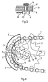
- FIG. 1 to 6 show a first embodiment the device according to the invention. Because of the small adjustment path of the support elements for Supporting the chain 1 forming swivel profiles 2, 3, this embodiment is suitable for bicycles with hub gear shift or without gear shift, where the sag of the chain 1 is limited. This is why the chain is for the purpose their transfer from a sprocket to a support element can only be lifted off the sprocket to a limited extent. This lifting takes care of the two swivel profiles 2, 3, which by twisting one Swivel cam 4 with its non-articulated ends are pivotable radially outwards according to the Arrows P1, P2.
- the two swivel profiles 2, 3 are each with their to the middle of the chain arch oriented ends around pivot points 5 one Frame plate 6 pivotable, in which short Eccentric lever 7 are connected with the swivel profiles are non-rotatably connected. This will move them to the middle of the chain arch oriented ends of the swivel profiles 2, 3 spreading them apart, as shown in FIG. 3, inside, which after releasing the chain through the gear more chain length for that Spreading the chain is available.
- the Frame plate 6 has, as can be seen in Fig. 2, an angled mounting flange 8, which is the end of the bearing slot 9 for the Includes rear wheel containing frame part 10 and by means of a through screw 11 with the latter connected is.
- the two swivel profiles 2, 3 are by means of tension springs 12 which on the Frame plate 6 are anchored in their starting position kept so that they are not inadvertently Engage with chain 1.
- the pivot cam 4 sits on one in the frame part 10 pivotally mounted pin 13 on the other end, a pivot lever 14 is attached.
- the pivot lever 14 engages with a corresponding one Bend the side stub 15 of the rear wheel, the hub 16 only by an outline is indicated.
- the rear sprocket On the stub axle 15 the rear sprocket is fixed in rotation 17, which is driven via the chain 1.
- the pivot lever 14 has on the rear Side of the stub shaft 15 one up protruding mandrel 18 which, when the Swivel lever 14 in the direction of arrow P3 starts the stub axle 15 and consequently this disengages from the bearing slot 9.
- the two support profiles 2, 3 comprise approximately U-shaped the sprocket 17 in the area of the chain 1, as illustrated in Fig. 2. You can see there also the pivot point 5 of the support profile 2 in the Frame plate 6.
- Swivel cam 4 With this on both sides associated inward protrusions 20 the support profiles 2, 3 together. Their the Swivel cams 4 adjacent flanks always kept in contact by means of the tension springs 12 and when pivoting the pivot cam 4 accordingly moved apart until the in Fig. 3rd shown maximum pivot position is reached.
- Fig. 6 shows a simplified representation in that there the frame plate 6 because of the better overview is omitted.
- the section shown in Fig. 4 according to IV-IV 3 shows - after disengaging the Gear 17 - one against the two support surfaces 19 adjacent to the side tension members 21 Chain link, the tension links 21 via a web 22 are connected.
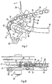
- FIG. 7 to 10 show a further embodiment of the invention, wherein the frame part 10 with the longitudinal slot 9 for receiving the wheel axle 23 of the rear wheel at its lower end Bearing eye 33 for articulating a lever for Tighten the chain in a chain gear shift having.
- Chain length for the transfer of chain 1 to support element designed as a segment plate 24 is available, its simple is sufficient Swivel mounting around a pivot point 25 on the frame 10.
- the segment plate 24 has on its circumference a support edge 26 with a radially projecting Tooth 27 at the top.
- the articulation point 25 of the segment sheet 24 in one Enclose frame part 10 in the rear area Mounting tab 31 stored, which by means of two screws 32 in the frame part 10 is attached.
- the tooth 27 of the support edge 26 facilitates the pivoting of the segment plate 24 in the direction of arrow P4 by chain 1 after the engagement of the tooth 27 in this is moved on the left according to arrow P5. Doing so by means of the tooth 27, the segment plate 24 automatically carried until the tooth 27 its in Fig. 9 has reached the end position shown, in which he is against you with his rounded flank Chain link 22 supports.
- this is First segment plate 24 along its circumference 90 ° axially inwards, then again 90 ° radially bent outwards so that the thus formed Support edge 26 exactly in the plane of the outer Sprocket 17 of the derailleur between this and the chain engages, so that ultimately the support edge 26 approximately in the middle on the inside the chain stays 22 attack.
Landscapes
- Engineering & Computer Science (AREA)
- General Engineering & Computer Science (AREA)
- Mechanical Engineering (AREA)
- Chemical & Material Sciences (AREA)
- Combustion & Propulsion (AREA)
- Transportation (AREA)
- Devices For Conveying Motion By Means Of Endless Flexible Members (AREA)
- Transmissions By Endless Flexible Members (AREA)
- Steering Devices For Bicycles And Motorcycles (AREA)
- Hand Tools For Fitting Together And Separating, Or Other Hand Tools (AREA)
Description
- Fig. 1
- eine schematische Seitenansicht der erfindungsgemäßen Vorrichtung mit zwei Schwenkprofilen in der Ausgangsposition als Schnitt gemäß I-I der Fig. 2,
- Fig. 2
- eine Draufsicht zu Fig. 1,
- Fig. 3
- eine Ansicht der Vorrichtung gemäß Fig. 1, jedoch in der Stützposition der Schwenkprofile,
- Fig. 4
- einen Schnitt gemäß IV-IV der Fig. 3,
- Fig. 5
- einen Schnitt gemäß V-V der Fig. 2,
- Fig. 6
- eine etwas vereinfachte Ansicht der Vorrichtung gemäß Fig. 1, jedoch in einer Zwischenposition der Schwenkprofile,
- Fig. 7
- eine schematische Seitenansicht einer anderen Ausführungsform der Vorrichtung mit einem verschwenkbaren Segmentblech in der Ausgangsposition,
- Fig. 8
- eine Draufsicht auf die Vorrichtung gemäß Fig. 7,
- Fig. 9
- eine Ansicht gemäß Fig. 7 mit in die Stützposition verschwenktem Segmentblech und
- Fig. 10
- eine Draufsicht zu Fig. 9.
Claims (16)
- Vorrichtung an einem Fahrrad zum Auskuppeln der Fahrradkette von einem Zahnkranz (17) des Hinterrads, mittels einer mit dem Fahrradrahmen verbundenen Führung zum Abstützen der Kette (1) in gestreckter Stellung zwecks Demontage des Hinterrads,
dadurch gekennzeichnet, daß die Führung ein in der Kettenebene verschwenkbares Stützelement umfaßt, welches aus einer von der Kette (1) entfernten Ausgangsposition in eine die Kette (1) von innen greifende Stützposition verschwenkbar ist. - Vorrichtung nach Anspruch 1,
dadurch gekennzeichnet, daß das Stützelement wenigstens eine in Richtung der Kette (1) bogenförmige Stützkante (26) aufweist, welche in der Stützposition an den Stegen (22) der Kettenglieder anliegt. - Vorrichtung nach Anspruch 1,
dadurch gekennzeichnet, daß das Stützelement wenigstens eine in Richtung der Kette (1) bogenförmige Stützfläche (19) aufweist, welche in der Stützposition an den Zuggliedern (21) einer Kettenseite anliegt. - Vorrichtung nach Anspruch 2,
dadurch gekennzeichnet, daß das Stützelement benachbart der Hinterradachse an dem deren Lagerschlitz (9) bildenden Rahmenteil (10) angelenkt ist, derart, daß es um den Anlenkpunkt (25) aus seiner Ausgangsposition von vorne in seine Stützposition nach hinten verschwenkbar ist. - Vorrichtung nach Anspruch 2,
dadurch gekennzeichnet, daß die Stützkante (26) wenigstens einen radial nach außen vorspringenden in die Kettenglieder eingreifenden Zahn (27) aufweist. - Vorrichtung nach Anspruch 2,
dadurch gekennzeichnet, daß die Stützkante (26) an einem Segmentblech (24) ausgebildet ist, welches an seinem Umfang axial nach innen gebogen ist und an seiner Innenkante einen radial nach außen gebogenen Rand in Form der Stützkante (26) aufweist. - Vorrichtung nach Anspruch 6,
dadurch gekennzeichnet, daß das Segmentblech (24) an einer an der Innenseite des dem äußersten Kettenrad (17) benachbarten Rahmenteils (10) angebrachten Befestigungslasche (31) angelenkt ist. - Vorrichtung nach Anspruch 6,
dadurch gekennzeichnet, daß am Segmentblech (24) ein axial nach außen vorspringender Fingerhebel (28) zu dessen Verschwenken vorgesehen ist. - Vorrichtung nach Anspruch 3,
dadurch gekennzeichnet, daß das Stützelement zwei Stützflächen (19) für die einander gegenüberliegenden Zugglieder (21) der Kette (1) aufweist, wobei die Stützflächen (19) als gegen den Zahnkranz (17) gerichtete Stege (22) eines die Kette (1) von drei Seiten umschließenden U-förmigen Schwenkprofils (2, 3) ausgebildet sind. - Vorrichtung nach Anspruch 9,
dadurch gekennzeichnet, daß das Schwenkprofil (2, 3) bogenförmig ausgebildet ist und an einem Ende um einen in mittlerer Höhe des Kettenbogens hinter der Kette (1) befindlichen rahmenfesten Schwenkpunkt (5) verschwenkbar ist, derart, daß die ausgeschwenkten Stützflächen (19) im Bereich des anderen Endes des Schwenkprofils (2, 3) die Kette (1) nach innen abstützen. - Vorrichtung nach Anspruch 10,
dadurch gekennzeichnet, daß zwei Schwenkprofile (2, 3) etwa symmetrisch zur Horizontalen durch die mittlere Höhe des Kettenbogens angeordnet sind, welche durch einen gemeinsamen Schwenkantrieb betätigbar sind. - Vorrichtung nach Anspruch 11,
dadurch gekennzeichnet, daß der Schwenkantrieb einen mittels eines Schwenkhebels (14) betätigbaren Schwenknocken (4) umfaßt, welcher mit Vorsprüngen (20) an den einander zugewandten Enden der Schwenkprofile (2, 3) zusammenwirkt, derart, daß die Schwenkprofile (2, 3) mit ihren gegenüberliegenden Enden von innen gegen die Kette (1) aufgespreizt werden. - Vorrichtung nach Anspruch 12,
dadurch gekennzeichnet, daß der den Lagerschlitz (9) bildende Rahmenteil (10) nach hinten mittels einer die Schwenkpunkte (5) für die Schwenkprofile aufnehmenden Rahmenplatte (6) verlängert ist. - Vorrichtung nach Anspruch 13,
dadurch gekennzeichnet, daß die Schwenkprofile (2, 3) derart exzentrisch an den Schwenkpunkten (5) der Rahmenplatte angelenkt sind, daß sich die einander zugewandten Enden der Schwenkprofile (2, 3) bei deren Aufspreizen zur Kette (1) hin bewegen. - Vorrichtung nach Anspruch 12,
dadurch gekennzeichnet, daß der Schwenkhebel (14) von unten um den zugeordneten Achsstummel (15) gebogen ist, welcher die der Ausgangsposition entsprechende obere Anschlagstellung bildet. - Vorrichtung nach Anspruch 15,
dadurch gekennzeichnet, daß der Schwenkhebel (14) dicht hinter dem Achsstummel (15) einen nach oben gerichteten Dorn (18) zum Ausrücken des Achsstummels (15) aus dem Lagerschlitz (9) aufweist.
Applications Claiming Priority (2)
| Application Number | Priority Date | Filing Date | Title |
|---|---|---|---|
| DE19620026A DE19620026C1 (de) | 1996-05-17 | 1996-05-17 | Vorrichtung zum Auskuppeln einer Fahrradkette |
| DE19620026 | 1996-05-17 |
Publications (3)
| Publication Number | Publication Date |
|---|---|
| EP0807569A2 EP0807569A2 (de) | 1997-11-19 |
| EP0807569A3 EP0807569A3 (de) | 1998-12-09 |
| EP0807569B1 true EP0807569B1 (de) | 2003-08-20 |
Family
ID=7794639
Family Applications (1)
| Application Number | Title | Priority Date | Filing Date |
|---|---|---|---|
| EP97103188A Expired - Lifetime EP0807569B1 (de) | 1996-05-17 | 1997-02-27 | Vorrichtung zum Auskuppeln einer Fahrradkette |
Country Status (3)
| Country | Link |
|---|---|
| EP (1) | EP0807569B1 (de) |
| AT (1) | ATE247577T1 (de) |
| DE (2) | DE19620026C1 (de) |
Families Citing this family (2)
| Publication number | Priority date | Publication date | Assignee | Title |
|---|---|---|---|---|
| DE102005006682B3 (de) * | 2005-02-15 | 2006-08-17 | Ulrich Rombach | Vorrichtung zum Abstützen der Antriebskette bei Fahrrädern |
| US12258090B2 (en) * | 2021-09-15 | 2025-03-25 | TILT Industries LLC | Chain separator for manual bike training |
Family Cites Families (7)
| Publication number | Priority date | Publication date | Assignee | Title |
|---|---|---|---|---|
| DE1118560B (de) * | 1958-05-16 | 1961-11-30 | Winkelhofer & Soehne Joh | Kettenraedergetriebe mit einer Kettenfuehrung |
| FR2172610A5 (de) * | 1972-02-17 | 1973-09-28 | Micmo | |
| CH569204A5 (de) * | 1972-09-15 | 1975-11-14 | Kropf Walter | |
| US3862487A (en) * | 1973-04-30 | 1975-01-28 | Gundy Kenneth Warren Van | Chain positioner for 10-speed bicycle |
| CH607823A5 (en) * | 1975-11-07 | 1978-11-15 | Tullio Campagnolo | Device enabling the bicycle transmission chain to be disengaged from the sprocket wheels of the free wheel |
| US4167125A (en) * | 1977-04-20 | 1979-09-11 | Eberhard Hedrich | Rear-wheel mounting for bicycle |
| FR2451855A1 (fr) * | 1979-03-20 | 1980-10-17 | Soulisse Jean | Repose chaine |
-
1996
- 1996-05-17 DE DE19620026A patent/DE19620026C1/de not_active Expired - Fee Related
-
1997
- 1997-02-27 DE DE59710598T patent/DE59710598D1/de not_active Expired - Fee Related
- 1997-02-27 EP EP97103188A patent/EP0807569B1/de not_active Expired - Lifetime
- 1997-02-27 AT AT97103188T patent/ATE247577T1/de not_active IP Right Cessation
Also Published As
| Publication number | Publication date |
|---|---|
| DE59710598D1 (de) | 2003-09-25 |
| DE19620026C1 (de) | 1997-07-24 |
| EP0807569A3 (de) | 1998-12-09 |
| EP0807569A2 (de) | 1997-11-19 |
| ATE247577T1 (de) | 2003-09-15 |
Similar Documents
| Publication | Publication Date | Title |
|---|---|---|
| DE2844122C2 (de) | Frontkettenschaltung für ein Fahrrad | |
| DE69500037T2 (de) | Vorrichtung zum Tragen von Gegenständen, insbesondere Fahrrädern, auf der Hinterseite eines Kraftfahrzeuges | |
| DE3922316B4 (de) | Neigungseinstellvorrichtung für die Rückenlehne von Sitzen | |
| DE69016320T2 (de) | Kettenradsatz für Fahrrad. | |
| DE69731523T2 (de) | Zweirad-Radnaben-Montagevorrichtung | |
| DE3525374C2 (de) | Höheneinstelleinrichtung für einen Fahrzeugsitz | |
| DE3308538C2 (de) | ||
| DE20206816U1 (de) | Roller | |
| DE2314554A1 (de) | Kettenschaltung mit aenderung des anstellwinkels des leitrades | |
| EP0800977A2 (de) | Transportvorrichtung mit motorisch angetriebener Treppensteigvorrichtung | |
| DE19607837A1 (de) | Vorrichtung zum Dekorieren von einzelnen Objekten | |
| DE2933362C2 (de) | ||
| DE10156992A1 (de) | Trittelementbefestigung für Personenbeförderer | |
| EP0807569B1 (de) | Vorrichtung zum Auskuppeln einer Fahrradkette | |
| DE69610140T2 (de) | Aufhängevorrichtung für Fahrräder | |
| DE3213474A1 (de) | Lastuebertragungs- oder -verschiebevorrichtung | |
| EP0512391B1 (de) | Verschiebevorrichtung für Filterplatten an einer Filterpresse | |
| EP0322694B1 (de) | Antriebvorrichtung für den Speisezylinder einer Kämmaschine | |
| DE102011056471B4 (de) | Roller mit Handantrieb | |
| EP0970599B1 (de) | Rundballenpresse | |
| DE10146799B4 (de) | Vorrichtung zum Formen von Brezen | |
| DE4101882C2 (de) | Verstellbeschlag für Fahrzeugsitze, insbesondere Kraftfahrzeugsitze | |
| DE9011220U1 (de) | Krankenfahrstuhl | |
| DE3507074A1 (de) | Endlosbahnanordnung | |
| DE1471850B2 (de) | Vorrichtung zur herstellung von rippenglas |
Legal Events
| Date | Code | Title | Description |
|---|---|---|---|
| PUAI | Public reference made under article 153(3) epc to a published international application that has entered the european phase |
Free format text: ORIGINAL CODE: 0009012 |
|
| AK | Designated contracting states |
Kind code of ref document: A2 Designated state(s): AT BE CH DE DK ES FI FR GB IE IT LI MC NL SE |
|
| PUAL | Search report despatched |
Free format text: ORIGINAL CODE: 0009013 |
|
| AK | Designated contracting states |
Kind code of ref document: A3 Designated state(s): AT BE CH DE DK ES FI FR GB IE IT LI MC NL SE |
|
| 17P | Request for examination filed |
Effective date: 19990312 |
|
| 17Q | First examination report despatched |
Effective date: 20020906 |
|
| GRAH | Despatch of communication of intention to grant a patent |
Free format text: ORIGINAL CODE: EPIDOS IGRA |
|
| GRAS | Grant fee paid |
Free format text: ORIGINAL CODE: EPIDOSNIGR3 |
|
| GRAA | (expected) grant |
Free format text: ORIGINAL CODE: 0009210 |
|
| AK | Designated contracting states |
Designated state(s): AT BE CH DE DK ES FI FR GB IE IT LI MC NL SE |
|
| PG25 | Lapsed in a contracting state [announced via postgrant information from national office to epo] |
Ref country code: NL Free format text: LAPSE BECAUSE OF FAILURE TO SUBMIT A TRANSLATION OF THE DESCRIPTION OR TO PAY THE FEE WITHIN THE PRESCRIBED TIME-LIMIT Effective date: 20030820 Ref country code: IT Free format text: LAPSE BECAUSE OF FAILURE TO SUBMIT A TRANSLATION OF THE DESCRIPTION OR TO PAY THE FEE WITHIN THE PRESCRIBED TIME-LIMIT;WARNING: LAPSES OF ITALIAN PATENTS WITH EFFECTIVE DATE BEFORE 2007 MAY HAVE OCCURRED AT ANY TIME BEFORE 2007. THE CORRECT EFFECTIVE DATE MAY BE DIFFERENT FROM THE ONE RECORDED. Effective date: 20030820 Ref country code: IE Free format text: LAPSE BECAUSE OF FAILURE TO SUBMIT A TRANSLATION OF THE DESCRIPTION OR TO PAY THE FEE WITHIN THE PRESCRIBED TIME-LIMIT Effective date: 20030820 Ref country code: GB Free format text: LAPSE BECAUSE OF FAILURE TO SUBMIT A TRANSLATION OF THE DESCRIPTION OR TO PAY THE FEE WITHIN THE PRESCRIBED TIME-LIMIT Effective date: 20030820 Ref country code: FR Free format text: LAPSE BECAUSE OF FAILURE TO SUBMIT A TRANSLATION OF THE DESCRIPTION OR TO PAY THE FEE WITHIN THE PRESCRIBED TIME-LIMIT Effective date: 20030820 Ref country code: FI Free format text: LAPSE BECAUSE OF FAILURE TO SUBMIT A TRANSLATION OF THE DESCRIPTION OR TO PAY THE FEE WITHIN THE PRESCRIBED TIME-LIMIT Effective date: 20030820 |
|
| REG | Reference to a national code |
Ref country code: GB Ref legal event code: FG4D Free format text: NOT ENGLISH |
|
| REG | Reference to a national code |
Ref country code: CH Ref legal event code: EP |
|
| REG | Reference to a national code |
Ref country code: IE Ref legal event code: FG4D Free format text: GERMAN |
|
| REF | Corresponds to: |
Ref document number: 59710598 Country of ref document: DE Date of ref document: 20030925 Kind code of ref document: P |
|
| PG25 | Lapsed in a contracting state [announced via postgrant information from national office to epo] |
Ref country code: SE Free format text: LAPSE BECAUSE OF FAILURE TO SUBMIT A TRANSLATION OF THE DESCRIPTION OR TO PAY THE FEE WITHIN THE PRESCRIBED TIME-LIMIT Effective date: 20031120 Ref country code: DK Free format text: LAPSE BECAUSE OF FAILURE TO SUBMIT A TRANSLATION OF THE DESCRIPTION OR TO PAY THE FEE WITHIN THE PRESCRIBED TIME-LIMIT Effective date: 20031120 |
|
| PG25 | Lapsed in a contracting state [announced via postgrant information from national office to epo] |
Ref country code: ES Free format text: LAPSE BECAUSE OF FAILURE TO SUBMIT A TRANSLATION OF THE DESCRIPTION OR TO PAY THE FEE WITHIN THE PRESCRIBED TIME-LIMIT Effective date: 20031201 |
|
| NLV1 | Nl: lapsed or annulled due to failure to fulfill the requirements of art. 29p and 29m of the patents act | ||
| GBV | Gb: ep patent (uk) treated as always having been void in accordance with gb section 77(7)/1977 [no translation filed] |
Effective date: 20030820 |
|
| PG25 | Lapsed in a contracting state [announced via postgrant information from national office to epo] |
Ref country code: AT Free format text: LAPSE BECAUSE OF NON-PAYMENT OF DUE FEES Effective date: 20040227 |
|
| PG25 | Lapsed in a contracting state [announced via postgrant information from national office to epo] |
Ref country code: MC Free format text: LAPSE BECAUSE OF NON-PAYMENT OF DUE FEES Effective date: 20040228 Ref country code: BE Free format text: LAPSE BECAUSE OF NON-PAYMENT OF DUE FEES Effective date: 20040228 |
|
| PG25 | Lapsed in a contracting state [announced via postgrant information from national office to epo] |
Ref country code: LI Free format text: LAPSE BECAUSE OF NON-PAYMENT OF DUE FEES Effective date: 20040229 Ref country code: CH Free format text: LAPSE BECAUSE OF NON-PAYMENT OF DUE FEES Effective date: 20040229 |
|
| REG | Reference to a national code |
Ref country code: IE Ref legal event code: FD4D |
|
| PGFP | Annual fee paid to national office [announced via postgrant information from national office to epo] |
Ref country code: DE Payment date: 20040427 Year of fee payment: 8 |
|
| PLBE | No opposition filed within time limit |
Free format text: ORIGINAL CODE: 0009261 |
|
| STAA | Information on the status of an ep patent application or granted ep patent |
Free format text: STATUS: NO OPPOSITION FILED WITHIN TIME LIMIT |
|
| 26N | No opposition filed |
Effective date: 20040524 |
|
| BERE | Be: lapsed |
Owner name: MARKETING & PROMOTION WUNDERLICH G.M.B.H. *MP Effective date: 20040228 |
|
| EN | Fr: translation not filed | ||
| REG | Reference to a national code |
Ref country code: CH Ref legal event code: PL |
|
| PG25 | Lapsed in a contracting state [announced via postgrant information from national office to epo] |
Ref country code: DE Free format text: LAPSE BECAUSE OF NON-PAYMENT OF DUE FEES Effective date: 20050901 |